PCB Production
Machining milling
Once we know the space, the general operation, and have performed the tests, we move on to generate the plate. For this week's task, I take up the circuit designed in week 6, to start producing the PCB.
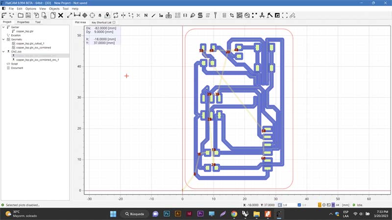
To do this, first select the application that will generate the file that will interpret the machine to make the PCB. I select FlatCAM. FlatCAM, an open source application used in the preparation of circuit designs to be manufactured by a CNC router, which generates G-Code for insulation routing from Gerber files generated in a CAD application for printed circuit boards (e.g. Eagle), is the software I used to input the Gerber file generated in Eagle to prepare the G-Code needed by the router to perform the machining.
I go to the website to download and install it on my computer (macOS 12.6.3 Monterey operating system)... but I had several problems to get it working 😩😰.
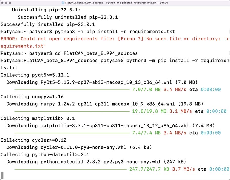
I resorted to several forums to solve the error; in one of the many times, I managed to get it to work, but finally I could not open a document to start preparing the file to process.
Fix problem for run FlatCAM in MacOS X - Monterey. No positive results 😩.
Finally, I had to use another computer, running Windows OS, to do the processing and get the engraving and cutting files I needed to produce my printed circuit board.
The router needs instructions to trace and cut a plate design. With FlatCAM you set some parameters and generate the .nc files to do the routing and cutting of the design. Some considerations:
- The tool type I used in production is C1.
- The tool diameters are expressed in decimals, like this: 1/32 inch = 0.79375 mm and 1/64 inch = 0.396875 mm.
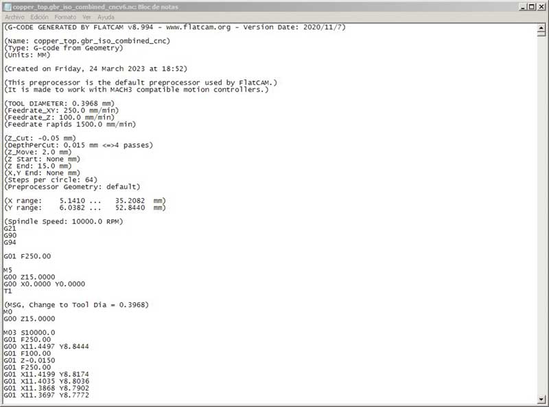
- Always indicate the spindle speed, otherwise it will not start turning (OBS: it is also recommended to open the generated code in a text editor and delete the line of code where "M6" is located).
- The
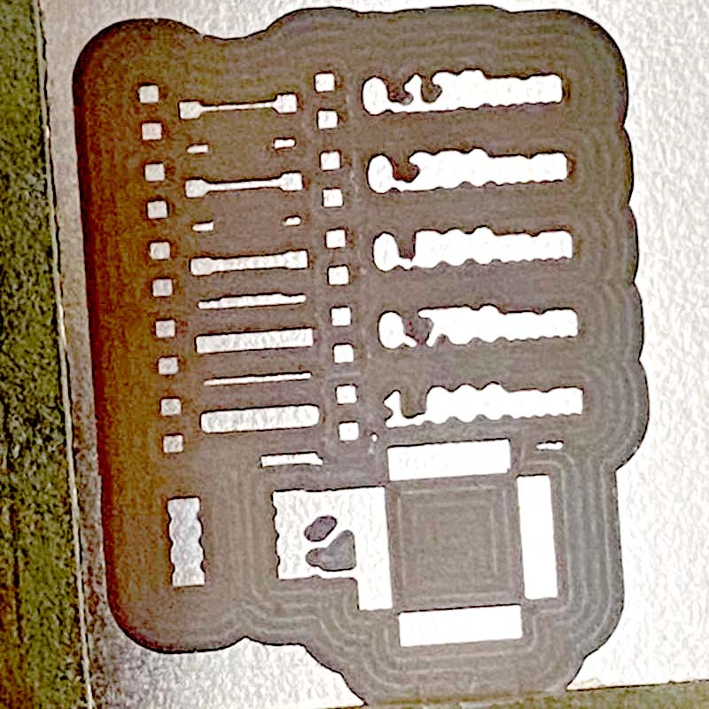
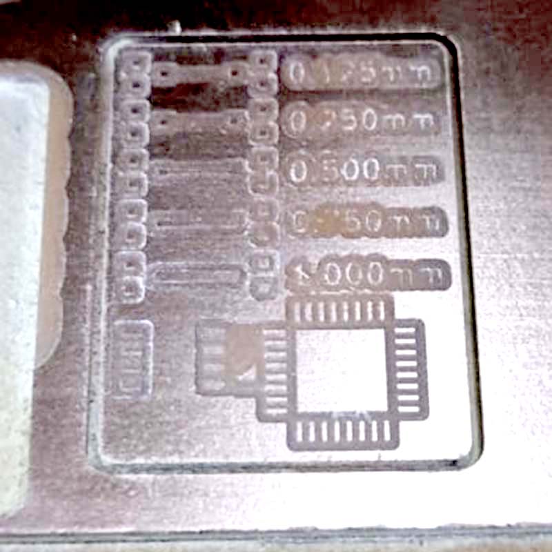
.nc files are then generated with 1/64 tool for traces and 1/35 tool for cut-out.
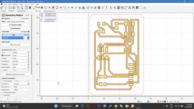
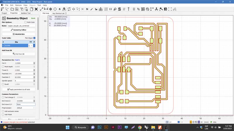
Top: FlatCAM, isolation of the trace with the 1/64 bur (left); isolation of the outer section with the 1/32 bur (right). Bottom: View of the stroke isolation path in FlatCAM (left); G-code text without the M6 line that causes the spindle not to initiate rotation.
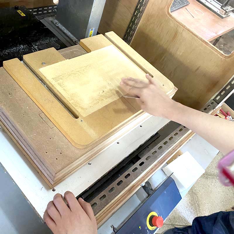
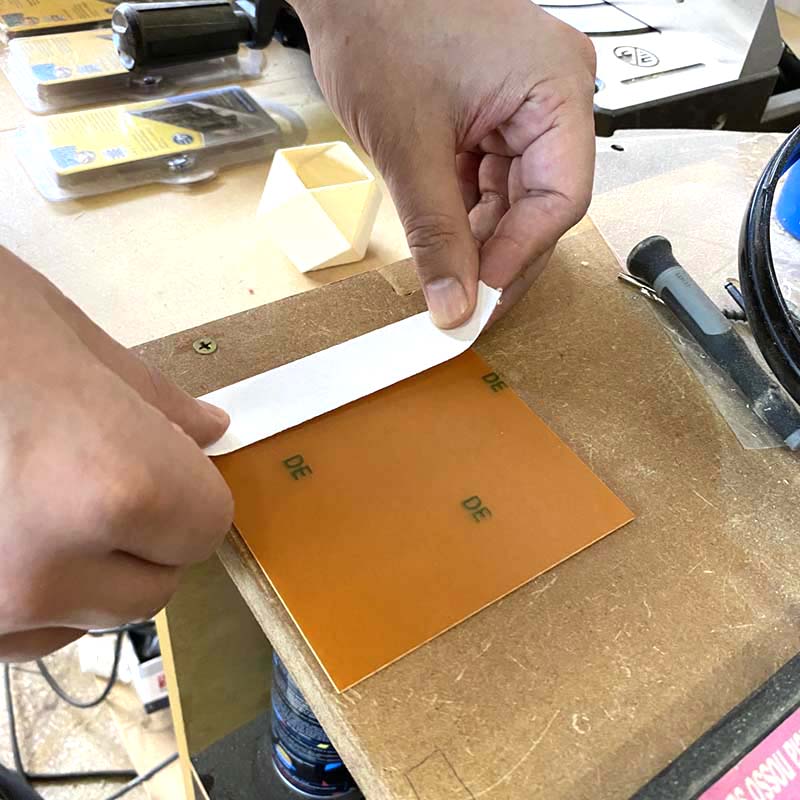
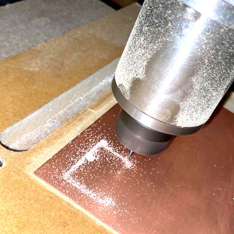
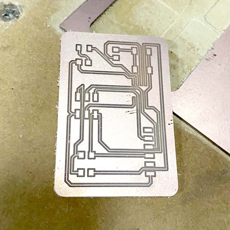
In the FabLab we had 1.8 mm copper plates for the production of printed circuit boards. The preparation of the board to be milled can be seen on the FabLab page.
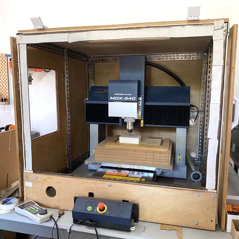
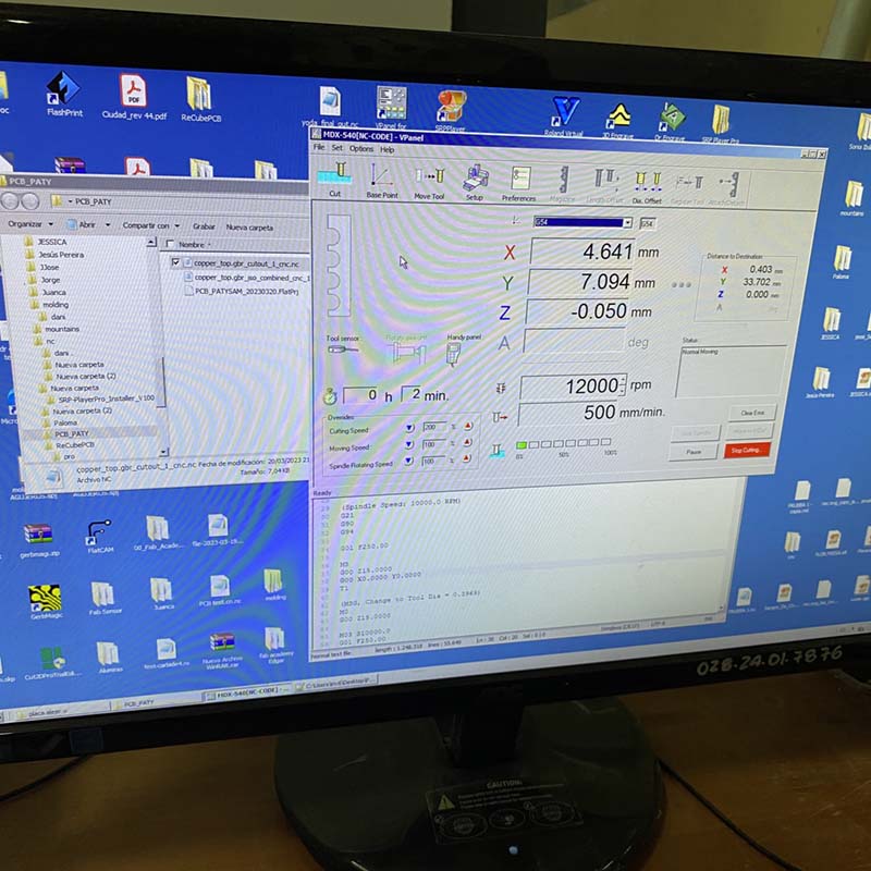
The software for the Roland MDX 540 CNC milling machine is VPanel MODELA PRO II, and the UI looks like this:
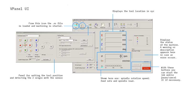 Vpanel UI
Welding process
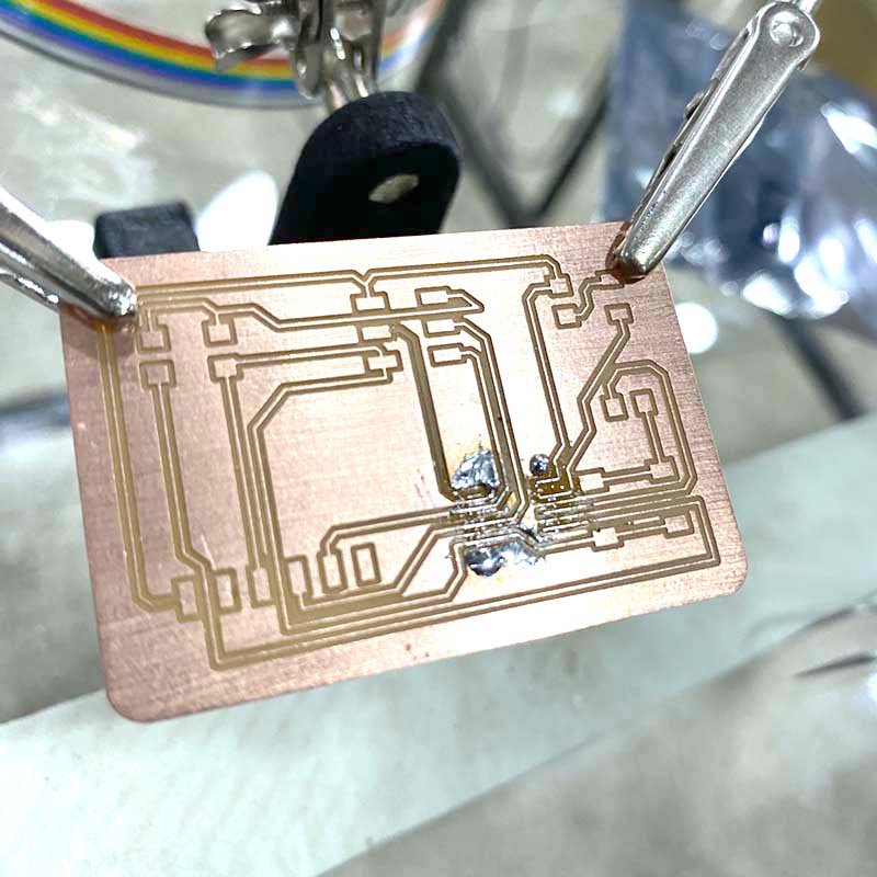
Once the board was ready, the next step was to solder the PCB components.
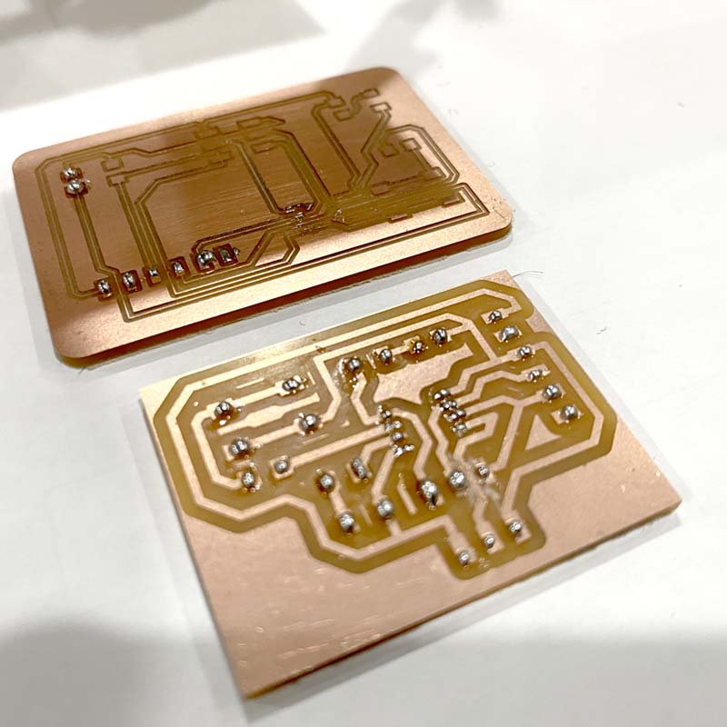
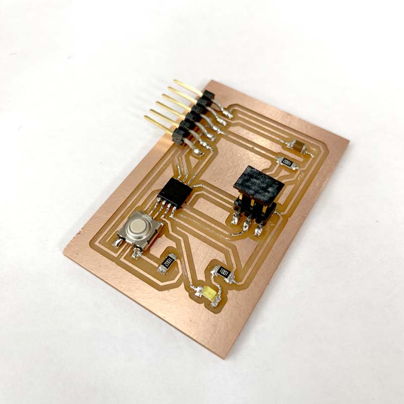
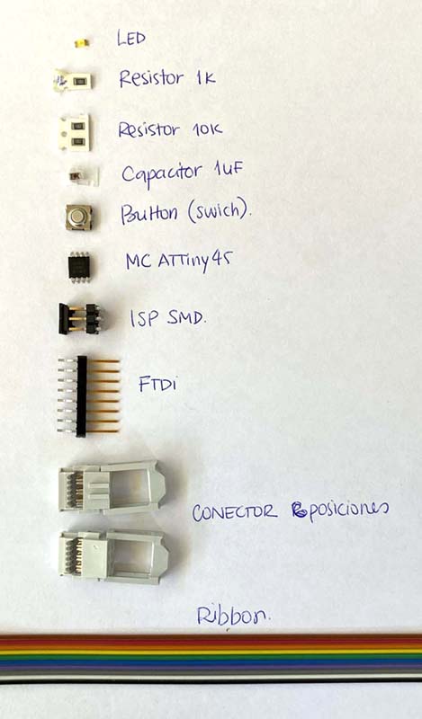 Components of my PCB.
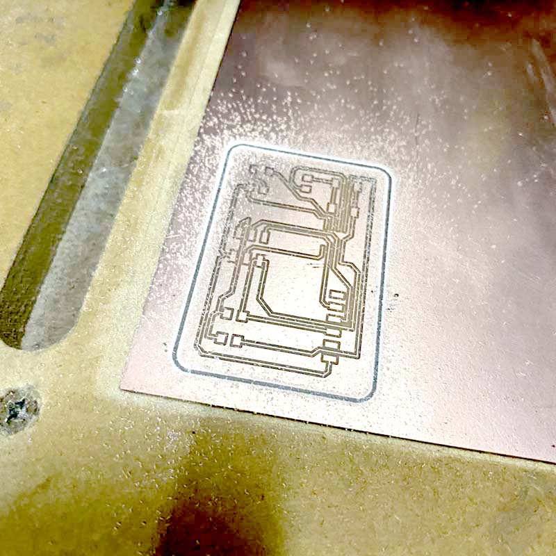
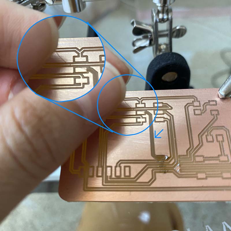
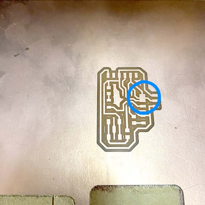
But again, there were some inconveniences like when soldering the first component, as the tracks were so thin, one of them came loose... so I had to re-machine it.
At the same time, I also went back to edit the circuit design in Eagle, this time modifying the thickness of the tracks; so the soldering process of components and then the programming, are still pending at the time of publication of this documentation.
‼️ In the next week I will be finishing the PCB.
Process update week 8: end of PCB production
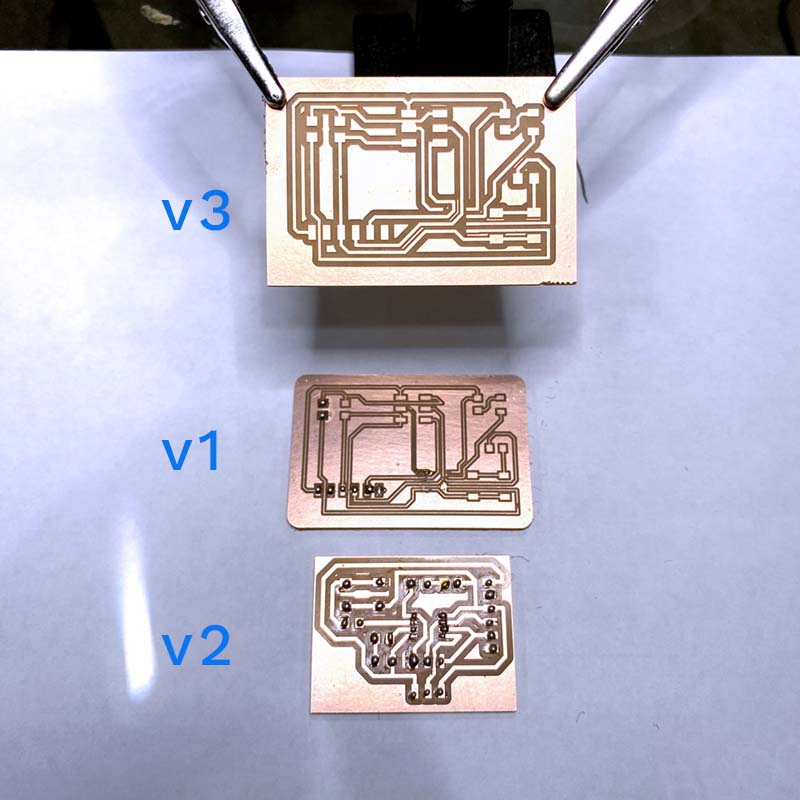
Updating week 8, I had mentioned that the first board I made had some issues. So, I machined a new board with some changes in the thickness of the tracks. This time they turned out better, and with less risk of coming off when soldering the components 😅 🙌🏼
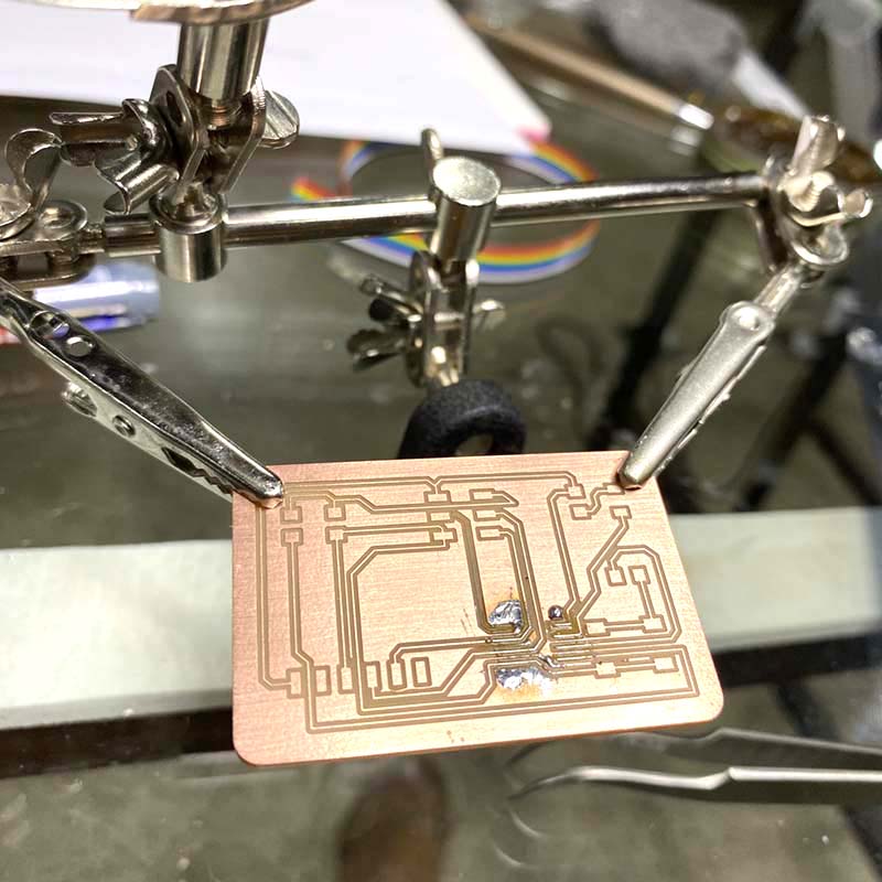
Alright, let's give this another go. This time, I tried a different circuit design. But, as luck would have it, we ran into some problems while milling the PCB: one of the tracks needed to be separated 😩. No worries though, I took advantage of the machined boards and practiced pre-tinning. Then, we went back to the original design with slightly thicker tracks. I'm currently in the process of soldering the components onto the new board.
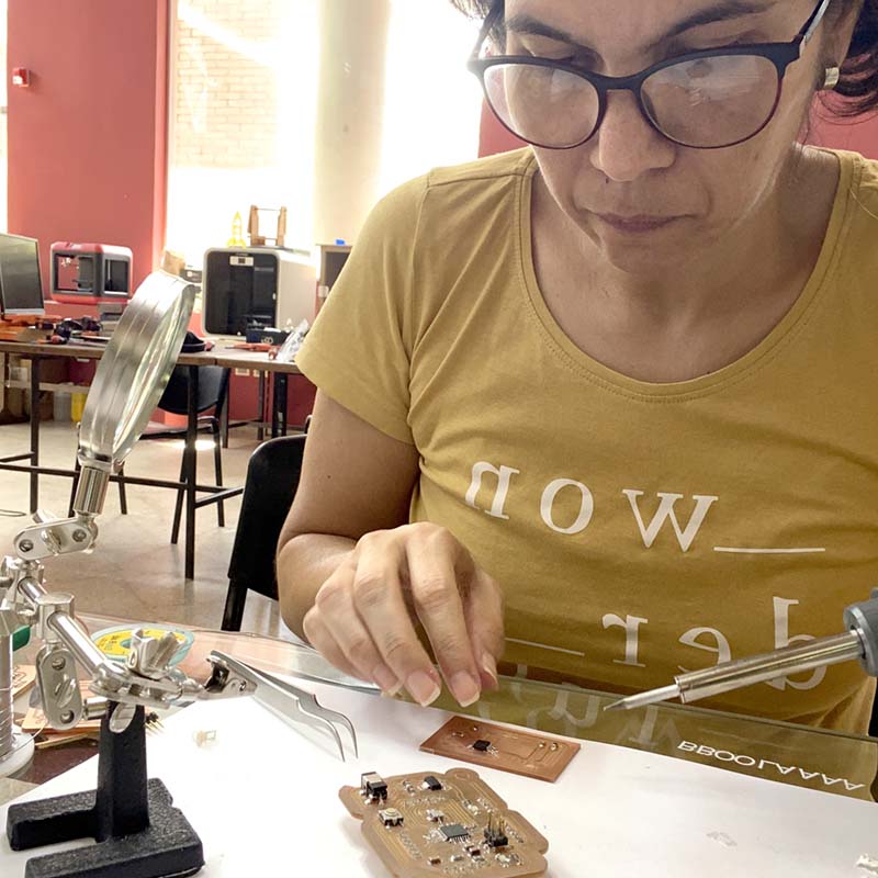
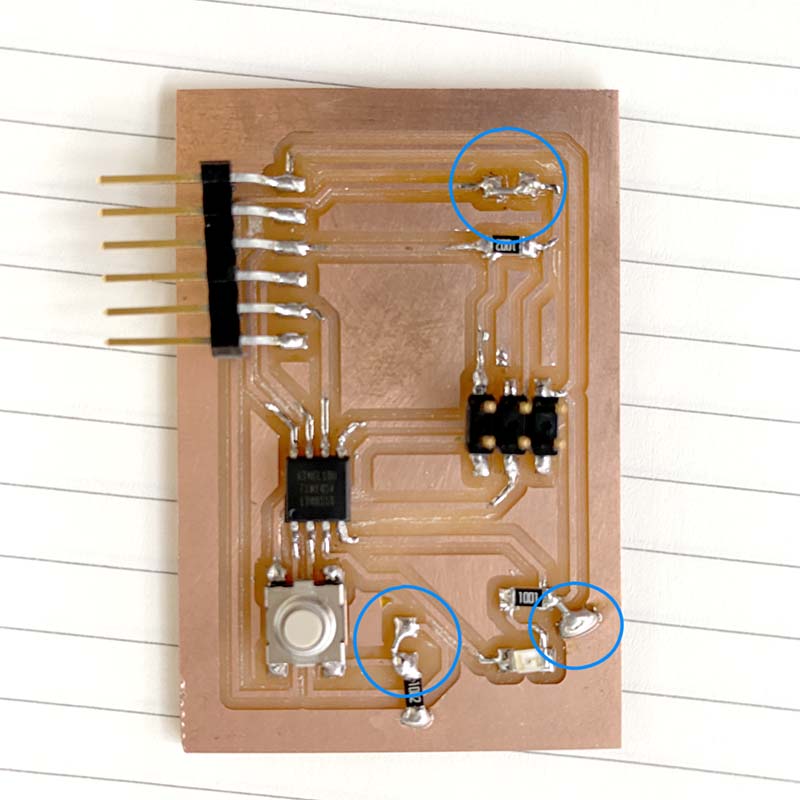
After that was done, we moved on to the functionality test, starting with the blink in the Arduino IDE. Unfortunately, in the first few tests, it didn't work ☹️. But, with the help of Abdón Troche (our local instructor) 🧑🏽🏫, we checked the scheme to verify the connections and found that some components weren't connected properly 😱. Abdón showed me how to solve the issue by making a 'bridge' connection with solder (not recommended, but it worked for our purposes) 😯.
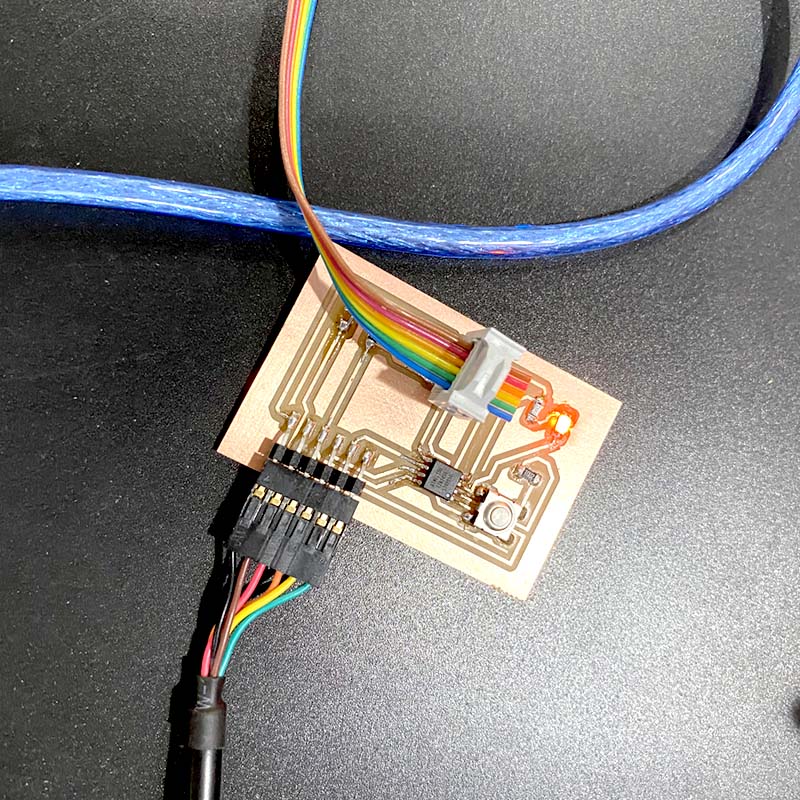
With the intervened board, we tested it and it worked 🙌🏼: we have blink. Then, we modified the code so that the LED could be turned on and off using the button on the board. After a few attempts, we managed to get the LED to turn on and off once again.
Code
                                            #include

                                                #define rxPin 5 // declarar el pin del RX
                                                #define txPin 4 // declarar el pin del TX

                                                // Set up a new SoftwareSerial object
                                                SoftwareSerial mySerial =  SoftwareSerial(rxPin, txPin); // Config de los pines Rx y Tx como serie de software

                                                // initialize digital pin LED.
                                                int ledPin = 3; // LED digital conectado al pin 3 - Según pinout ATTiny 45

                                                void setup()  {
                                                    // Define pin modes for TX and RX
                                                    pinMode(rxPin, INPUT);
                                                    pinMode(txPin, OUTPUT);

                                                    // Set the baud rate for the SoftwareSerial object
                                                    mySerial.begin(9600);
                                                }

                                                void loop() {
                                                    if (mySerial.available() > 0) {
                                                        mySerial.read();
                                                    }
                                                    pinMode(ledPin, OUTPUT);      //Configures the LED pin as an output

                                                  // fade in from min to max in increments of 5 points:

                                                    for (int fadeValue = 0 ; fadeValue <= 255; fadeValue += 5) {

                                                  // sets the value (range from 0 to 255):

                                                    analogWrite(ledPin, fadeValue);

                                                  // wait for 30 milliseconds to see the dimming effect

                                                    delay(30);

                                                    }
                                                  // fade out from max to min in increments of 5 points:

                                                  for (int fadeValue = 255 ; fadeValue >= 0; fadeValue -= 5) {

                                                  // sets the value (range from 0 to 255):

                                                    analogWrite(ledPin, fadeValue);

                                                  // wait for 30 milliseconds to see the dimming effect

                                                    delay(30);

                                                    }
                                                }

And that's the story of my journey in weeks 8 (and 9 😅) where I was able to design, produce, and program an electronic PCB board 😎. It was amazing 🙌🏼.
In the following weeks I made a new adjustment to the design of the plate, and you have it available among the files to download.