11. Input devices
This week I was tasked with measuring the values of an input device. My group chose to use a time of flight sensor and you can see our process in our group documentation site.
Initial Testing
To start this week off I looked at Nidhie Dhiman’s documentation regarding the sensor used for her final project since we would be using the same sensor. in her documentation she expained how she wired her sensor to get it to work. She connected the SDA pin on the sensor to the SCL pin on her chip and the SCL pin on the sensor to the SDA pin on her chip. She also connected the 3v pin to the 3v3 pin on the Xiao RP2040 chip. after I wired everything the same way, I went to the Adafruit Flora Color senseor code website for more information on how to code the sensor. From the website I got this code which required two libraries wire.h and Adafruit_TCS34725.h. I downloaded everything I needed regarding these libraries from the same website I got the code from. Once the libraries I needed were included the website suggested that I run the TCS34725 sketch which would let me know if my color sensor was working properly. Once i ran the sketch I opened the serial monitor to see the changing RGB values of the different materials I held the sensor to.
 #include <Wire.h>
#include "Adafruit_TCS34725.h"

// Pick analog outputs, for the UNO these three work well
// use ~560  ohm resistor between Red & Blue, ~1K for green (its brighter)
#define redpin A1
#define greenpin A0
#define bluepin A2
// for a common anode LED, connect the common pin to +5V
// for common cathode, connect the common to ground

// set to false if using a common cathode LED
#define commonAnode true

// our RGB -> eye-recognized gamma color
byte gammatable[256];


Adafruit_TCS34725 tcs = Adafruit_TCS34725(TCS34725_INTEGRATIONTIME_50MS, TCS34725_GAIN_4X);

void setup() {
  Serial.begin(9600);
  //Serial.println("Color View Test!");

  if (tcs.begin()) {
    //Serial.println("Found sensor");
  } else {
    Serial.println("No TCS34725 found ... check your connections");
    while (1); // halt!
  }

  // use these three pins to drive an LED
#if defined(ARDUINO_ARCH_ESP32)
  ledcAttachPin(redpin, 1);
  ledcSetup(1, 12000, 8);
  ledcAttachPin(greenpin, 2);
  ledcSetup(2, 12000, 8);
  ledcAttachPin(bluepin, 3);
  ledcSetup(3, 12000, 8);
#else
  pinMode(redpin, OUTPUT);
  pinMode(greenpin, OUTPUT);
  pinMode(bluepin, OUTPUT);
#endif

  // thanks PhilB for this gamma table!
  // it helps convert RGB colors to what humans see
  for (int i=0; i<256; i++) {
    float x = i;
    x /= 255;
    x = pow(x, 2.5);
    x *= 255;

    if (commonAnode) {
      gammatable[i] = 255 - x;
    } else {
      gammatable[i] = x;
    }
    //Serial.println(gammatable[i]);
  }
}

// The commented out code in loop is example of getRawData with clear value.
// Processing example colorview.pde can work with this kind of data too, but It requires manual conversion to
// [0-255] RGB value. You can still uncomments parts of colorview.pde and play with clear value.
void loop() {
  float red, green, blue;

  tcs.setInterrupt(false);  // turn on LED

  delay(60);  // takes 50ms to read

  tcs.getRGB(&red, &green, &blue);

  tcs.setInterrupt(true);  // turn off LED

  Serial.print("R:\t"); Serial.print(int(red));
  Serial.print("\tG:\t"); Serial.print(int(green));
  Serial.print("\tB:\t"); Serial.print(int(blue));

//  Serial.print("\t");
//  Serial.print((int)red, HEX); Serial.print((int)green, HEX); Serial.print((int)blue, HEX);
  Serial.print("\n");

//  uint16_t red, green, blue, clear;
//
//  tcs.setInterrupt(false);  // turn on LED
//
//  delay(60);  // takes 50ms to read
//
//  tcs.getRawData(&red, &green, &blue, &clear);
//
//  tcs.setInterrupt(true);  // turn off LED
//
//  Serial.print("C:\t"); Serial.print(int(clear));
//  Serial.print("R:\t"); Serial.print(int(red));
//  Serial.print("\tG:\t"); Serial.print(int(green));
//  Serial.print("\tB:\t"); Serial.print(int(blue));
//  Serial.println();

#if defined(ARDUINO_ARCH_ESP32)
  ledcWrite(1, gammatable[(int)red]);
  ledcWrite(2, gammatable[(int)green]);
  ledcWrite(3, gammatable[(int)blue]);
#else
  analogWrite(redpin, gammatable[(int)red]);
  analogWrite(greenpin, gammatable[(int)green]);
  analogWrite(bluepin, gammatable[(int)blue]);
#endif
}
Once I knew that my sensor was working proporly I moved on to the color view portion of the website where they use and RGB LED to display the color of the items on the LED. Instead of using the RDG LED, I used a RGB LED strip because it is closer to what will be used in ky final project. Because the RGB LEDs have 4 pads that I can connect to the same pins that the LED would connect to. I connected the red pad to pin 3 on the board, the blue pad to pin 6, and the green pad to pin 5 on the board. I then reuploaded the same code from previously. This time when I moved the sensor around I saw both the serial monitor values as well as the RGB values displayed on the LED Strip.
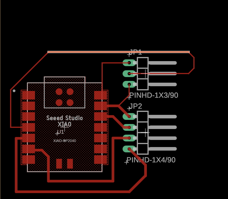
PCB Board
The next step in this process was to create the board. I used the same design concept as the board I made previously during outputs week. This board would also be used for my final project and her is the file for the board.
milled/ soldered board
here is my milled and soldered bored that I made using the same process as in week 6

Final Test
Once everything was built and soldered, I tested the board using the same code as earlier and it worked. After I tested and it worked I convered the board in clear nail polish to avoid ripping any traces.
## Problems encountered
The main problem that I encountered was including the libraries for the code. I origninally struggled with the wrie.h library for the I2C because It was not installed and I struggled to find the download for the library. After looking through the informaion provided by an Arduino I2C question site where I learned that the wire.h library was included in the Arduino AVR Boards download in the Arduino IDE.
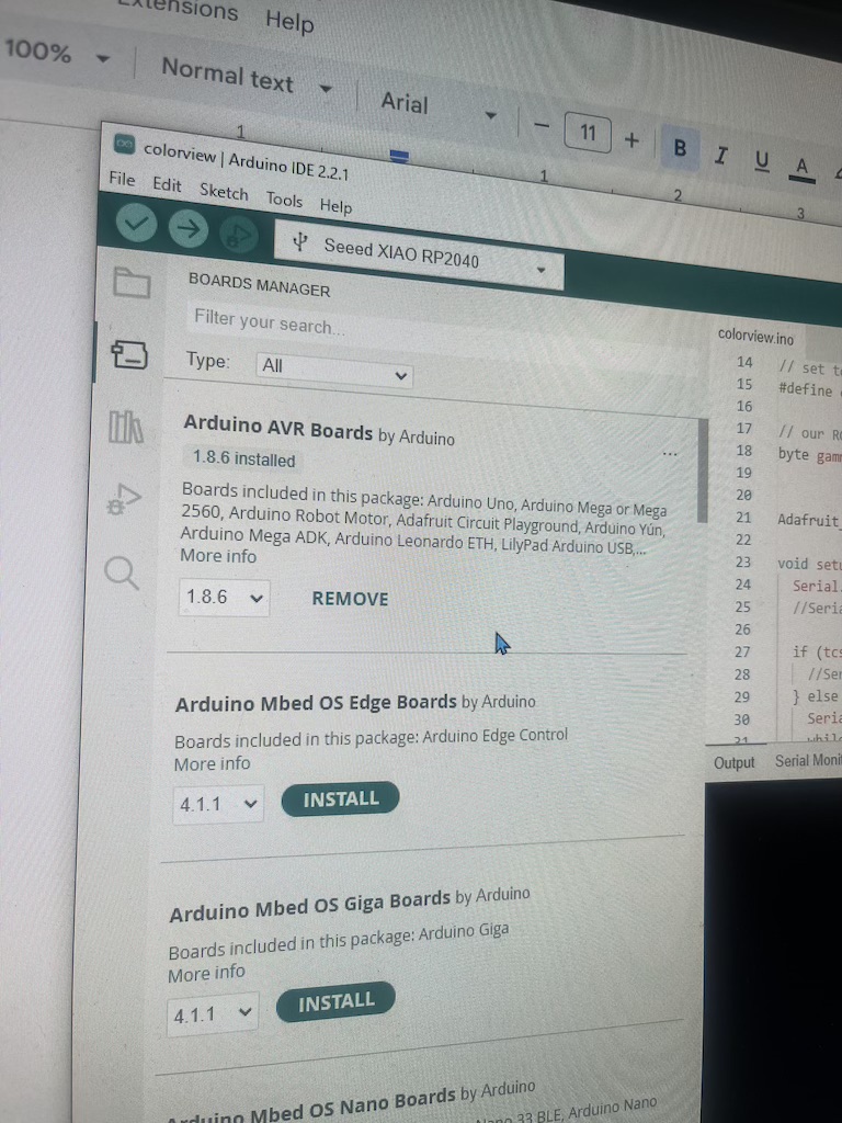
I updated this board manager then the wire.h worked.
Reflection
The newest thing I learned about would be the entire concept of I2C. I always knew that you could program on device to react to the data from another device, but I was unaware of how it worked and what it was called. I never knew what the SDA and SCL pins were for and after reading the adafruit information on I2C I understood the concept much better.