3. Computer Controlled Cutting
vinyl cutting
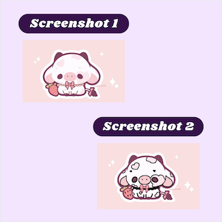
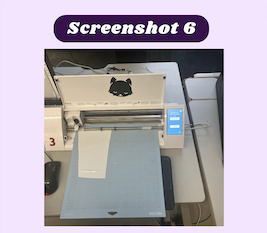
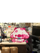
For my vinyl sticker, I decided to use an image of a strawberry cow. When I originally imported the image I wanted to use, I realized some of the colors were too light to be picked up by Silhouette Studio, the software we use to communicate with our vinyl cutters (Screenshot 1). To resolve this, I imported the image I wanted into notability and outlined the colors that were too light with a black pen (screenshot 2). I then put the new image into Silhouette Studio and it picked up everything I wanted to cut. After that, I sized up the image and used the trace panel to select the trace area. Once I selected the entire trace area and everything I wanted then highlighted yellow (screenshot 3), I pushed trace, and the outlines of what I wanted to be cut highlighted red. I then copied and pasted that image 3 times so that way I could use multiple different colors. I took a piece of light pink, dark pink, and green vinyl and pressed it on the cutting map with a green scraper (screenshot 4). I then loaded the cut map into the vinyl cutter and sent the design to start cutting (screenshot 5). Once it was finished I unloaded the mat and removed the vinyl sheets. I then took dark pink, the color I wanted to use as the outline and I weeded the unnecessary vinyl pieces that I did not want in my final product. From there I took the white vinyl pieces and used them to fill in the areas that I wanted to be white (screenshot 6). I followed this step for all the remaining colors. Once I was done I took piece a of transfer tape and used a scraper to stick all the vinyl together to make sure they all stayed in place. I then used that transfer tape to apply the sticker where I wanted it to go.


Final Product:
Parametric design
For my laser-cut design, I decided to make a spherical shape that you could input a material thickness and it would adjust the entire design to fit that adjustment. The first thing I took into consideration while making this was how I needed to be sure that all of my sketches were fully constrained.
Piece 1
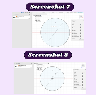
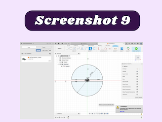
I started my design by creating a circle with a diameter of 3in from there I used a construction line from the origin that was a set distance away from the center of the design (screenshot 7). I then created another construction line from the origin (screenshot 8). Using the equal constraint I made both lines the same length. I then made a regular line that extended from the end of the construction lines that with the equal constraint was the same length as the construction lines I made earlier. I then repeated this extending in the opposite direction as the first line. After this step, I made two lines that stretch from the bottom of the vertical lines I made to the edge of the circle. I then did the same on the other side of the vertical line and used the equivalence constraint to keep them the same (screenshot 9). The next step was to use the trim tool to remove the extra part of the circle between the two lines. The last part of the design was the half-sized notch in the circle. to make this, I made a construction line from the beginning of the line above it and brought it all the way down to the edge of the circle. From there I made a regular line from the midpoint of the construction line to the edge of the circle. Next, I made a horizontal line from the top of the half-length line and used the equal constraint to make it the same size as the construction line in the middle of the circle. after that, I repeated that process for the other half of the rectangle and used the trim tool to remove the extra circle piece in the middle of the rectangular shape (screenshot 10). This completed the first piece of the sphere.

Piece 2
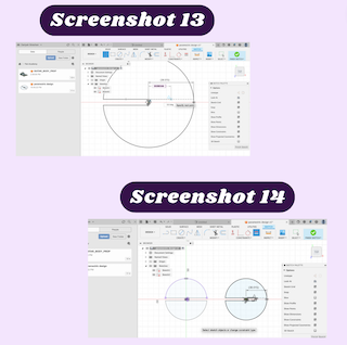
For the second part of the design, I first created a circle and made it the same size as the original circle (screenshot 11). At first, I struggled with making the circle itself fully constrained, but after some thought, I realized that the reason the circle was not fully constrained is that it was not set in place. to fix this, I used the fix/unfix constraint to keep the circle in place (screenshot 12). From there I made two construction lines in the center of the circle the same as the first one. I then made a line that extended from the center of the circle to the edge of the circle (screenshot 13). After that, I repeated the previous step on the opposite side of the construction line. Lastly, I trimmed out the extra piece of the circle in between the rectangular shape (screenshot 14).

Piece 3
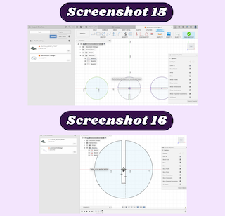
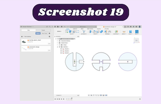
The final piece of the design was made in a very similar way to the other two pieces. I first followed the same 4 steps as I did for the second circle (screenshot 15). I created a 3/4 length rectangular shape the same way I did for the second circle (screenshot 16). After that, I created a 1/4 length rectangle starting from the edge of the circle the same way I did for the first part (screenshot 17 & 18). Once I finished my design, I decided to test it to make sure that it was truly parametric. I did this by changing the dimension of the center line in the first sketch. When I changed it, all the other lines also changed, proving my design is parametric (screenshot 19).

## Exploring file
The final thing I needed to do was laser-cut my design. To do this I first need to set the user parameters. To do this I went under the modify tab in Fusion 360 and selected the user parameters option. From there I changed the dimension of the horizontal line constraint to the thickness of the material I wanted to use, cardboard (0.125in), and I changed the circle’s diameter to fit how big I wanted my ball to be, 3in. I later remembered the kerf of the laser and added .002 into the parameter for the material thickness. After that, I saved my file so I could export it. A problem I ran into while trying to export my file was not being able to export my file and a .svg or .pdf. To overcome this I exported my file as a .dxf file which Corel Draw can work with. Another issue I had with exporting my file, was that when I imported my .dxf file into Corel Draw, it also imported my construction lines, which I had to manually delete. I found it strange that the construction lines that I used to create my design would show up in Corel Draw when I imported it in, but it was an easy fix, so I did not pay it too much mind (screenshot 20).
you may download my files here
Laser cutting
To cut my design I just used the lab approved workflow that I always follow while using the laser cutter. I opened the Corel Draw file on the desktop connected to the laser cutter and ensured that everything I wanted to vector was set to hairline in Corel Draw. After that I sent the file off to print and it opened the epilogue settings application. I changed the setting to accommodate the materials I wanted to cut (screenshot 21). After that I focused the laser, I watched the laser cut my design to make sure I didn’t start a fire. I then assembled the pieces and finished my parametric design (image 1-3).

Group work
My group consist of myself, Ginny Foster, and Stuart Christhilf, Dylan Ferro, and David Tian. We were tasked with characterizing the laser cutter’s focus, power, speed, rate, kerf, and joint clearance. Here is the group site we documented on.