2. Computer-aided design
This week I explored different CAD software including FreeCAD, GIMP, Cuttle, Fusion 360, and Corel Draw.
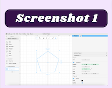
Cuttle- Tutorial
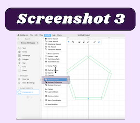
The first CAD software I decided to try out was Cuttle. After creating my account, I opened a new project and followed this tutorial to learn the basics of Cuttle. The first thing I did was place a polygon in the workspace (screenshot 1). From there I experimented with geometry snapping and the rotational repeat tool in the modifier tab (screenshot 2). I specified the number of rotations I wanted (5) and continued through the tutorial. Another important modifier cuttle has is the boolean union modifier (screenshot 3). This modifier combines selected shapes and makes them into one. You can also change the color of selected objects that way later on you can engrave or score your shapes. I used the pen tool to draw shapes with lines and used the anchor handles to manipulate the shape of the drawing (screenshots 4 & 5). After making a paisley droplet (screenshot 6), I then continued to create shapes like stars, circles, and hearts (screenshot 7). There was also an option for pre-made emojis, which I used to create the perfect hearts in my file, linked here. I enjoyed working in cuttle because it was fairly simple and easy to navigate. I still however prefer Corel Draw because obtaining certain shapes and tools is easier.


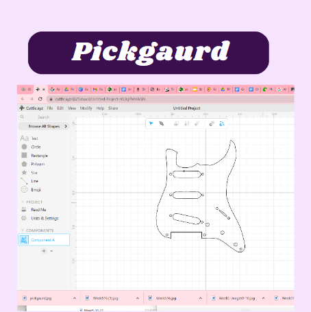
Cuttle- final project
I used cuttle to help me create a pickgaurd that I could use for my final project. To make the pick gaurd, I imported a guide for the proportions of the pickgaurd I wanted and used the pen took to trace around the image. After I got the general shape I used the circle tool to go over the smaller perfect circles for the screws. I then went back and used the anchors to further shape the pickgaurd to smooth out the rough edges. The final result was still very rough because it is difficult to make the exact shape you want in cuttle. Pickgaurd file
GIMP
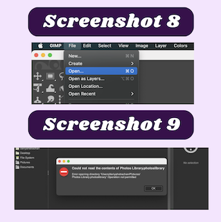
The second CAD software I explored was GIMP. Following the instructions from two different GIMP tutorials (tutorial 1 and tutorial 2), I learned about scaling, rotating, cropping, and creating images. To practice this I wanted to use my Fab Academy website logo. Right off the bat, I was having issues importing images from my laptop into GIMP. I would select the files tab on my laptop then it would open (screenshot 8). Once I tried to select the folder that the image of my logo was in, it would show an error that GIMP did not have access to the folder (screenshot 9). After watching this youtube video I realized that instead of accessing my files through GIMP, I should find the image I want to use in my computer’s files and drag and drop them into GIMP.
Once I successfully imported my image into GIMP, I went to the “Image” tab the selected the resize option (screenshot 10). I then change the size of my image to 337x336 (screenshot 11). I also experimented with the resolutions and other resizing values (px, in, mm).

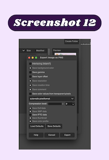
Changing the file size of the image was also very helpful because of the limited storage space in my repo. When exporting the image to my downloads folder, the option to change several different settings came up, however, I was not interested in making any of these changes (screenshot 12).
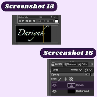
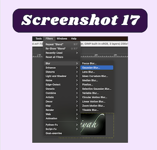
Moving on from the basics of GIMP, I created my simple floating logo. I started by creating a new image (screenshot 13). I used the bucket fill tool to add black to the entirety of the image (screenshot 14). I then created a text box approximately the same size as the black rectangle (screenshot 15). I wanted to change the font of the text, so I went to the right side of my screen and right-clicked the text icon (screenshot 16). By selecting the “edit text on canvas” option, I was able to change the font of my text. In the filters tab, I applied a bur effect to my text (screenshot 17). At first, was having trouble understanding why the blur effect was not visible, but after a few minutes of playing around with the filter, I realized that the filter would only be effective if I was in the layer with the text selected. After this realization I decided to duplicate the text and set the blur effect to 13.5 on one of the layers, this gave the effect of light emanating off the letters. I also changed the color of the text to a light light yellow/ gold color. I was pretty happy with my logo so I saved it and exported it into my downloads. I then zipped it and linked it here. I found GIMP very hard to navigate because the tutorial that I was following was done on a windows device. I could not find many of the tools shown in the tutorial, so my final product looks significantly different than the tutorial, but I did the best I could.

Corel Draw
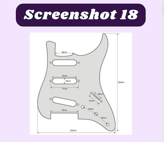
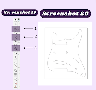
Because I already have experience using Corel Draw to design vector-based designs, I decided to create the pick guard for my guitar. to do this I used an image from the internet as a guide for dimensions and shape (screenshot 18). After importing my guide image into Corel Draw, I used the B-Spline tool to create the round curves in my design (screenshot 19-2). I then used the circle tool while holding shift to create perfect circles(screenshot 19-3). I then used the 3-point ellipse tool to create ovals that I used the line tool to connect. After I had everything connected, I used the segment delete tool to remove half of the circle that was unnecessary (screenshot 19-1). I then grouped all of the shapes I made and set the dimensions to 8.78in x 11.142 (screenshot 20). To conclude this file I set every line to hairline, that way it will cut my lines instead of engraving them. linked here
FreeCAD
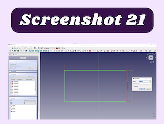
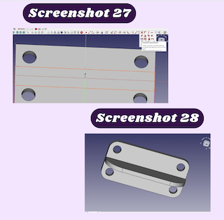
I followed this tutorial to get a general understanding of how FreeCAD works. With a general understanding of how to use FreeCAD, I began working through another tutorial that took a deeper dive into FreeCAD. The first step I took in FreeCAD was creating a rectangle that was fully constrained (screenshot 21). This was done by selecting the centered rectangle and setting dimensions to that the rectangle will not move. After doing that, I used the pad tool to extrude the rectangle (screenshot 22). Then I created 4 circles on the top of the pad (screenshot 23). I needed to make all the circles the same size by selecting each circle and using the constrain equal tool (screenshot 24). I also needed to constrain these and make them the same distance apart, so I used the external geometry tool to create a point that I could select and use for setting dimensions and constraints. After setting this external geometry point, I used it to set the circles 10mm from the point horizontally and vertically (screenshot 25). After constraining one of the circles I used the vertical and horizontal constraints to ensure that all the circles moved with each other. I then used another external geometry point I created to constrain the circle opposite to the first one (screenshot 26). From there all the circles were green and fully constrained. I then needed to pocket the circles I made. After this was done, I created a rectangle on the top plane. I used the constrained geometry to center the rectangle along with a 5mm dimension (screenshot 27). I then padded the rectangle and applied a 10mm fillet around the ends of the base as well as a 20mm fillet on the top of the bracket (screenshot 28). linked here


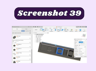
Fusion 360- tutorial
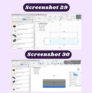
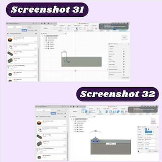
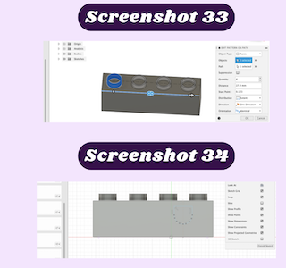
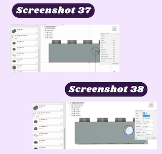
I used Fusion 360 to create a lego brick. I started creating the lego by drawing a rectangle that was 7.8 x 31.8 cm. from there I extruded the rectangle up 9.6 cm (screenshots 29 & 30). I then drew a circle with a 4.8 cm diameter and extruded it (screenshots 31 & 32). After that, I used the shell tool to hollow out the rectangle and circle. I shelled the rectangle to 1.5 cm and the circle to 3.2 cm. I then used the pattern on a path tool to make replicas of the original circle (screenshot 33). After selecting the circle as the object and the length of the rectangle, I changed the copy amount to 4 and dragged the line evenly across the shape. I then used the circle tool to create a construction line that I placed 7.9 cm away from the edge and 5.8cm away from the bottom of the rectangle. I then used the fit point spline tool and traced the bottom half of the circle. after that, I used the line tool to connect the semi-circle to the top of the rectangle (Screenshot 34). I drew another circle at the bottom of the rectangle and connected it to the semi-circle. Then I extruded the entire shape through the rectangle (Screenshot 35). I turned on the task analysis tool to view the inside of the design (screenshot 36). After that, I made two circles one 6.2cm and the other 4.8cm from the center of the semi-circle (screenshot 37). I extruded the smaller circle through the design, creating a hole. For the larger circle, I only extruded it 0.7cm(screenshot 38). finishing the designing process, I used the pattern tool to create 3 replicas placing each 8cm apart (screenshot 39). linked here