10. Machine week
The machine I made with my group is used to mix a soda (sprite) with a syrup flavor of you choosing. You can read more about the project on the student group B group site.
The Goal
We plan to achieve this by creating a tool with wheels on it that we could attach the plate for the cup to sit on. Next we plan to add a pulley system with a belt that will move the plate from one side of the machine to the other. After the machine adds the soda and the syrup, it will be mixed by a whisk. The whisk will move up and down on the Y axis, that way the cup will not tip over when it is in the mixing area. It will then bring the cup back to the starting position.
Research
To better execute our plan to make this machine we looked at machines that had similar purposes as our own. We came across a man on YouTube that made essentially what we were aiming for, however he did not go into detail about how he made his project. We then looked at the Pizza Maker that a previous Fab Academy group made. We also use the Prusa Minis for inspiration and we decided with could use their design for our pulley system with a few modifications. Lastly we considered the ideas of the other two groups in our lab to see if any of their ideas could somehow be used to aid our machine.

Our Plan
Drawing:
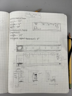
Stuart Christhilf drew out a guide for how we planned to make our machine. We also ball parked dimensions, so we would know approximately how large our machine would be and what materials we would need.
CAD design:
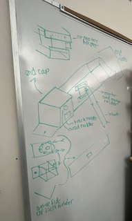
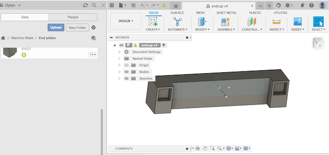
Stuart also made a Fusion 360 simulation of how how our project would ideally work.
Breakdown of my portion:
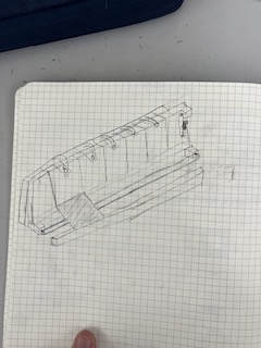
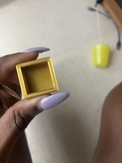
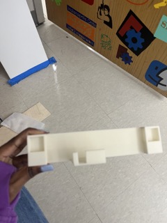
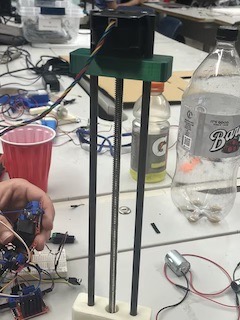
Ginny Foster drew this picture (image 1), which helped me visualize the endcaps of the machine that would hold together the guide rails and extrusions we planned to use. This endcap would also allow space to store our motor at a 180 degree angle, so we would be able to attach the belt to it. Originally we wanted to make guide rails that went over the extrusions and use ball-barrings to move the plate back and forth, but we decided to instead use a mechanism with wheels to move the plate. This change made my design easier because I would not have to take into consideration the guide rails. I realized later on that I would need to also design an area for the DC motor to rest as well as an area for the spool at the other end of the belt.
Getting started
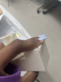
To start the design for the endcaps, I first took measurements of the extrusions we planned to use. With those dimensions, I made a and 3d printed a test piece to see if my design would fit properly. In Fusion 360 I made a square with a depth of .5in. I then shelled that to be the same dimensions as the extrusions and sent it off to print. After it finished printing , I took the piece and attempted to place it on top of the extrusions, but they were too small to fix. I thought about where I could have gone wrong and I realized that to make one piece it into another they can not both be the same size. I then made the shell size about 1mm larger in all four sides. I printed it again and it fit perfectly.

Designing and Testing the X axis endcap
v1:
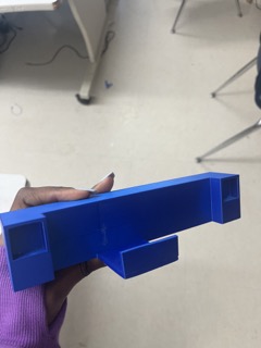
After I found a size that matched the extrusions we would be using, I then used those dimensions to create a end plate that consisted of one end piece on on side, I 1in block connected to a block that was about 8in across. After I had an L shape, I made a construction line down the center of the middle connector and I mirrored the joint to connect the extrusions to it. Once I had that design I printed it to see if it would work for the project and tested it.
test 1:
The first iteration of the endcap design was mildly off, so when the extrusions were inserted it cracked.
v2:
To fix the problem mentioned earlier, I slightly adjusted the size of the each of the inner walls of the endcap by 2mm on all four sides. I then printed it and tested it
test 2:
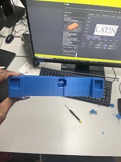
This end cap fit quite well and we used it for initial machine testing.
v3:
The next change to the design I made was adding a space for the motor to sit while moving the bed plate across the machine.
test 3:
This addition of an area for the motor fit the motor well enough, but with the way we wanted to orientate the motor, there was a problem fitting the port in for the cords.
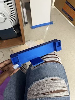
v4:
To fix the port issue, I simply made a slot for the port to fit into.
test 4:
This time everything fit nicely and this was used for the final product. (however it did break later on and was reprinted)
v5
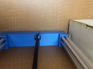
The next thing I needed to add to was a slot for the opposite side of the belt where the spool would be. To do this, I used the v4 design and the construction lines along with it as a guide. I settled on this design for the spool holder.

test 5
The spool holder was slightly too small

v6
I slightly opened up the space a little, so the wheel will not get stuck against the pocket made for it
test 6
This version worked and was used in the final product.
Designing and Testing the y-axis endcaps
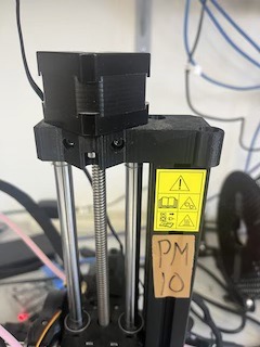
For this I based my deign off of the Prusa mini Z axis endcaps. I used similar sizing as the Prusa mini’s (approximately 3.5in across) and I made a box with three holes total, two that had a tight fit for the metal dowels and a very loose fit for the z axis motor. That way, the motor will not grind against the printed piece. This only required one version and did not need to be redesigned.
bearing holder
The next thing I designed was the holder for the bearings for the Z-axis. I printed this piece in 2 pieces so the bearings will both fit in place together. I simply made a rectangle where based off of the design of the Z-axis endcaps and kept the distance spacing the same between where the metal dowels went and created a space for the bearings to sit in. after that was printed the case was superglued together and placed on the metal dowels. this would allow the z-axis motor the move while staying in place.
Files
Linked here are all om my final files I used to make this project.
Final video
Issues with my designs and Reflection
One of the most notable issues with the endcaps that I made, what that the motor holder I made broke. I believe this is due to the filament not being able to support the the stress the motor was putting on it. This taught me ti be aware of the strength of the materials I planned on using and to know how the materials I used would affect the final product. Next time I think I will make the infill a higher percentage this will allow the 3d print to be for sturdy and reduce the chances of it breaking.