8. Electronics production
This week was dedicated to producing a PCB board as well as soldering it together. As a group we were tasked with characterizing our labs Bantam milling machine, as seen here on my group site
Soldering
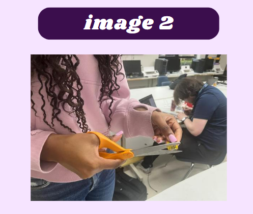
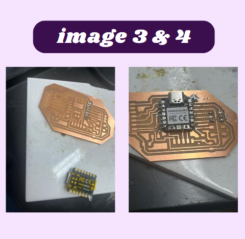
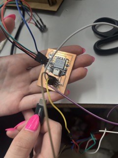
I started off by soldering a board with a Xaio- RP2040 produced by Adrián Torres to get a feel for electronic production and how they can turn out. Once I collected all of the necessary components (image 1), I started by putting insolating tape on the bottom of the Xiao- RP2040 (image 2). After that, I began to solder everything together. I started with the Xiao- RP2040 and I just simply put solder on the pads and the pin holes of the Xiao- RP2040 and melted them together (images 3 & 4). Once the Xiao- RP2040 was done I moved on to the header pins. I used the same method to solder the header pins and did for the Xiao- RP2040, but when I tried to reposition one of the header pins, I ripped a trace on the board and needed to mill a new one board. Once I had my new board, I resoldered everything and continued to solder the rest of the components. The final piece I soldered was the LED, but when I tested the board, nothing was happening. I looked at the board to see if I could find a short. I noticed a solder bridge on the seeed and I removed it with a solder sucker and tested it again and the seeed lit up (images 5 & 6). I also incorrectly soldered the LED due to its polarity. I unsoldered the LED and replaced it with a new one in the correct positions and tested the board to see if it worked, it did! This board was later used for testing in my group work.


Eagle Designing
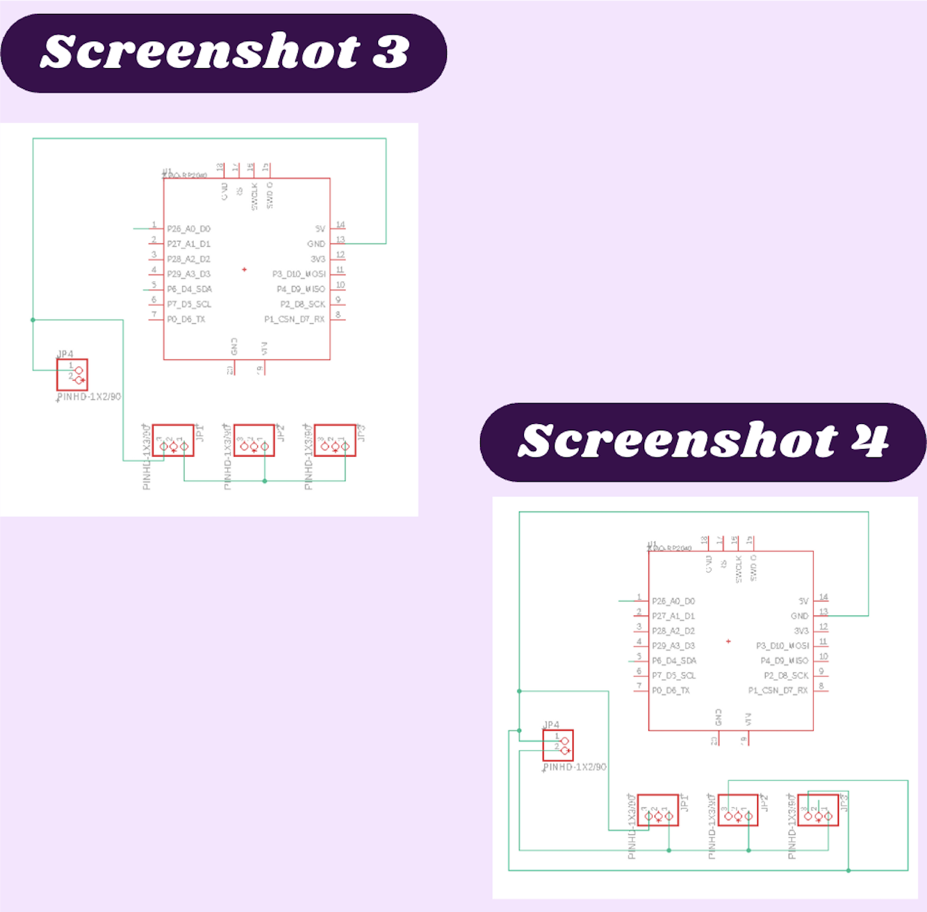
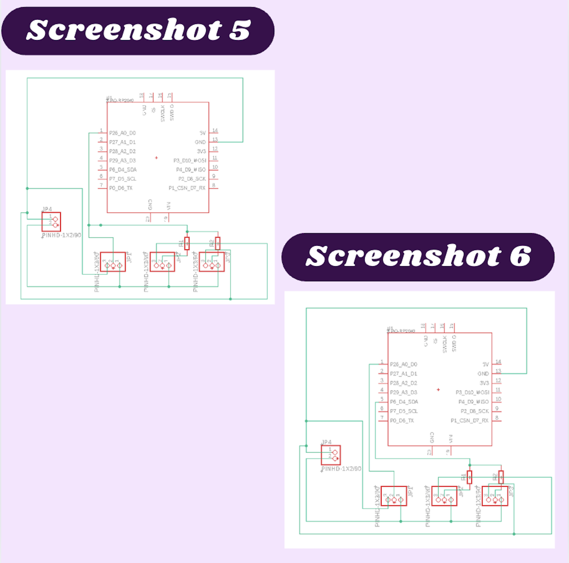
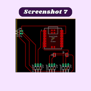
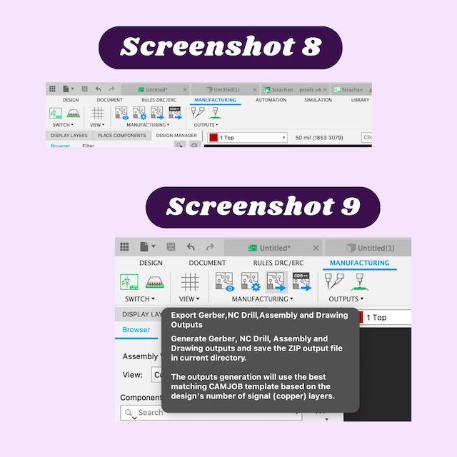
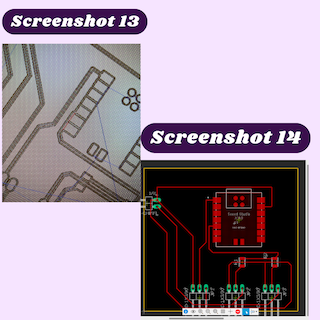
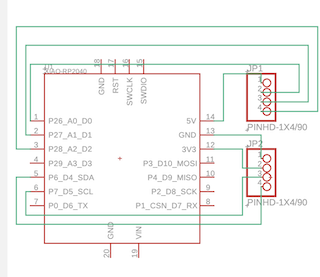
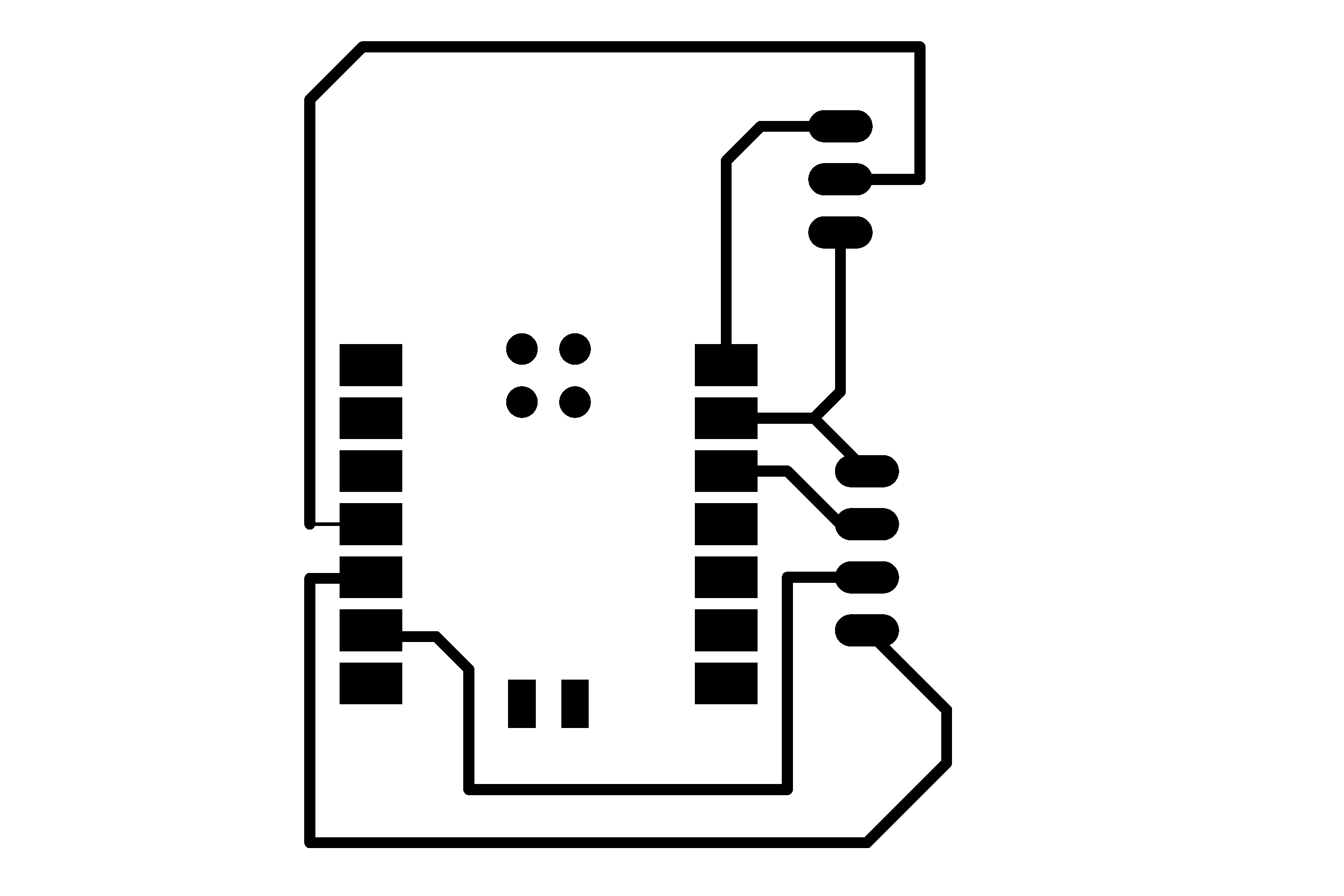
When I first imported my TinkerCAD design I looked it over and realized there were several things I needed to change including making the Arduino, neopixles, and USB into header pins. While I was changing out my electronics, I realized I could make this entire project easier by switching out the ATtiny chip I wanted to use for a Seeed Xiao RP2040 chip instead. That way I could eliminate the need for the Arduino and code it directly from the microcontroller. Because I needed to change so many things about the schematic, I decided to delete everything I had previously and create a new schematic. I started gathering all of the things that I would need from the libraries I had including neopixels, a Seeed Xiao RP2040 chip, and a USB. began wiring everything together, then I realized there was no need to have either a USB or neopixles in my schematic. I then replaced them all with header pins that would not only be easier to wire but also easier to solder and test with later on. Once I made that change in my design, I started with the ground and connected everything that needed a ground together (screenshot 3). From there I moved on to power. Because I am using an external power source, I used to power being supplied from there to power the neopixles and the Xiao RP2040 chip (screenshot 4). After the power was connected I needed to connect the output header pin I would be using for my neopixles. This is where I ran into a problem. The power and the ground connections that ran connected the middle two header pins were cutting off the output pin, so I could not connect the output pin to the chip I was using. I decided to combat this by using a 0 ohm resister to jump a connection and lead to the pin on the Xiao RP2040 chip (screenshot 5). I originally connected all of my neopixles to the same pin but I realized that because I wanted to use a different light pattern for one of the neopixle strips, I could not have then shared a pin. I kept the one group of header pins that did not require a 0 ohm resister separate and connected it to its pin on the chip. For the other two, I connected them together because they would be using the same code and put them on a different pin (screenshot 6). I then switched to the PCB editor to add the nets and change the board shape. I connected all the nets in a way that everything I needed would be connected (screenshot 7). I then exported my board as a Gerber file so that I could mill it out (screenshot 8 & 9).
Milling- setup
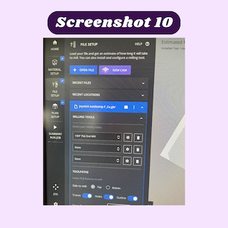
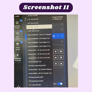
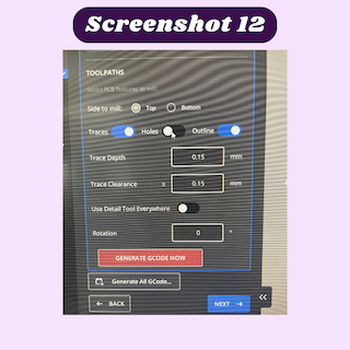
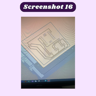
I then used the bantam software to mill out my board. I would normally start by installing the bit I wanted to use, however, the bit I wanted (1/64 endmill) was already installed in the machine. I then took a piece of Nitto tape and used it to secure the copper onto the bed. Once that was done I moved on to the files setup portion of milling (screenshot 10). I downloaded my file from the google drive folder that I uploaded it onto. From there I looked through the different layers it downloaded and selected the copper top and profile files and put them into the downloads folder. After that was done I followed the instructions the bantam software provided for milling a board. Because I already set up the bit and the material I jumped to uploading the files I wanted to mill. I deleted the project that someone else had on the board already and imported my files. From there I cleared the option for holes and changed the outline cut to the profile cut I downloaded from Eagle. Once all the settings I needed to change were changed, I looked at the bit that was selected to mill with. The program automatically selected a 1/32 bit, but that was not what I was using, so I changed the bit to a 1/64 flat endmill bit and clicked the next button (screenshot 11). The next part of the process was the offset. The offset was automatically set to 4mm for the x and y and 0mm for the Z axes (screenshot 1), but I was receiving an error message that said “Toolpath may cause the spindle to retract too far”. This error message confused me for a bit until I realized what exactly the plan offset was. This is where the bit will go to start milling the PCB board. I changed the offset manually with the command arrows to be in the corner of the copper. I also noticed red lines in places that were too small to be milled with a 1/64, so I needed to go back to my design and space out my traces. Once I did that I reimported my file, I looked over everything and there were no red lines or warnings, so once that was updated everything was ready to mill and I pressed the mill all button.


Soldering- v1
while soldering this board I realized I did not actually need header pins soldered in the spots where I placed header pin in the design. while removing the headerpins, I ripped a trace and decided to redesign by board to work with a Xiao Rp2040 instead.
Redesigning
schematic
For this board I wanted to reduce the amount of neopixels I would be using for my final project, so I decided to only light up the perimeter of the shelf. I needed two sets of four header pins for the neopixels and for the color sensor. I connected the header pins for the color sensor to the ground, 3.3V, SDA, and SCL pins of the color sensor. I then moved onto the neopixles. I used neopixels that had red, green, and blue pads, so I connected each color to a pin on the Xiao Rp2040. and connected the 5v power to the 5v power pin.
PCB board
Next I needed to add net connections to each component so it could be milled. once that was done, I made the overall size of the board as small as possible to minimize the amount of space it would take up.

Milling and soldering
I then followed all of the steps I mentioned earlier and milled out my new board. I then surface mount soldered the header pins to the correct space and the Xiao Rp2040 in its place. once that was done, I when to test the board, but I noticed a major flaw, one set if header pins were placed directly in front of the cable port.
To fix this I simply moved the set of header pins further to the side of the board and remilled it.

I soldered the new version of the board and connected the appropriate parts of the color sensor and neopixels with female to female jumper wires.
Code
following Mrs. Dhiman’s advice, I perused the Adafruit website to find a code to test out my board. The website provided me with this Aurduino code:
#include <Wire.h>
#include "Adafruit_TCS34725.h"

// Pick analog outputs, for the UNO these three work well
// use ~560  ohm resistor between Red & Blue, ~1K for green (its brighter)
#define redpin A1
#define greenpin A0
#define bluepin A2
// for a common anode LED, connect the common pin to +5V
// for common cathode, connect the common to ground

// set to false if using a common cathode LED
#define commonAnode true

// our RGB -> eye-recognized gamma color
byte gammatable[256];


Adafruit_TCS34725 tcs = Adafruit_TCS34725(TCS34725_INTEGRATIONTIME_50MS, TCS34725_GAIN_4X);

void setup() {
  Serial.begin(9600);
  //Serial.println("Color View Test!");

  if (tcs.begin()) {
    //Serial.println("Found sensor");
  } else {
    Serial.println("No TCS34725 found ... check your connections");
    while (1); // halt!
  }

  // use these three pins to drive an LED
#if defined(ARDUINO_ARCH_ESP32)
  ledcAttachPin(redpin, 1);
  ledcSetup(1, 12000, 8);
  ledcAttachPin(greenpin, 2);
  ledcSetup(2, 12000, 8);
  ledcAttachPin(bluepin, 3);
  ledcSetup(3, 12000, 8);
#else
  pinMode(redpin, OUTPUT);
  pinMode(greenpin, OUTPUT);
  pinMode(bluepin, OUTPUT);
#endif

  // thanks PhilB for this gamma table!
  // it helps convert RGB colors to what humans see
  for (int i=0; i<256; i++) {
    float x = i;
    x /= 255;
    x = pow(x, 2.5);
    x *= 255;

    if (commonAnode) {
      gammatable[i] = 255 - x;
    } else {
      gammatable[i] = x;
    }
    //Serial.println(gammatable[i]);
  }
}

// The commented out code in loop is example of getRawData with clear value.
// Processing example colorview.pde can work with this kind of data too, but It requires manual conversion to
// [0-255] RGB value. You can still uncomments parts of colorview.pde and play with clear value.
void loop() {
  float red, green, blue;

  tcs.setInterrupt(false);  // turn on LED

  delay(60);  // takes 50ms to read

  tcs.getRGB(&red, &green, &blue);

  tcs.setInterrupt(true);  // turn off LED

  Serial.print("R:\t"); Serial.print(int(red));
  Serial.print("\tG:\t"); Serial.print(int(green));
  Serial.print("\tB:\t"); Serial.print(int(blue));

//  Serial.print("\t");
//  Serial.print((int)red, HEX); Serial.print((int)green, HEX); Serial.print((int)blue, HEX);
  Serial.print("\n");

//  uint16_t red, green, blue, clear;
//
//  tcs.setInterrupt(false);  // turn on LED
//
//  delay(60);  // takes 50ms to read
//
//  tcs.getRawData(&red, &green, &blue, &clear);
//
//  tcs.setInterrupt(true);  // turn off LED
//
//  Serial.print("C:\t"); Serial.print(int(clear));
//  Serial.print("R:\t"); Serial.print(int(red));
//  Serial.print("\tG:\t"); Serial.print(int(green));
//  Serial.print("\tB:\t"); Serial.print(int(blue));
//  Serial.println();


#if defined(ARDUINO_ARCH_ESP32)
  ledcWrite(1, gammatable[(int)red]);
  ledcWrite(2, gammatable[(int)green]);
  ledcWrite(3, gammatable[(int)blue]);
#else
  analogWrite(redpin, gammatable[(int)red]);
  analogWrite(greenpin, gammatable[(int)green]);
  analogWrite(bluepin, gammatable[(int)blue]);
#endif
}
I used Aurdino IDE to upload the code after selecting the board (xaio rp2040) that I would be using from the “select board” options. I then changed the pins in the given code to match those of the LED strip on the pcb board. After that I plugged in the Seeed Xaio Rp2040 to the computer, selected the appropriate board and COM port , then uploaded the code. At first I was receiving the same error message over and over again essentially saying that the Xiao was not connected. Later on Ginny pointed out that I had Thonny running in the background along with other Arduino tabs. She said that other tabs could interfere with the connection of the board. After I closed out all of the other tabs I had opened, I noticed that the the board was connecting properly. Once the code was uploaded, I noticed it started working:
PCB files
linked here and Trace PNG and Outline PNG
Reflection
while making this board I ripped several traces without even noticing. I learned about the importance of trace size and the best ways to prevent ripping a trace. After I milled this board and got it to work, I covered every trace with clear nail polish.That way the traces would be practically impossible to rip on accident.