
Week 04. Electronics Production
Like the previous week, there are two types of assignments, one group and one individual. In my case being alone in the Fab Lab, I do both.
- Characterize the design rules for your PCB production process: document feeds, speeds, plunge rate, depth of cut (traces and outline) and tooling.. ✔
- Make an in-circuit programmer by milling and stuffing the PCB, test it, then optionally try other PCB fabrication process. ✔
- Linked to the group assignment page. ✔
- Documented how you made (mill, stuff, solder) the board. ✔
- Documented that your board is functional. ✔
- Explained any problems and how you fixed them. ✔
- Included a ‘hero shot’ of your board. ✔
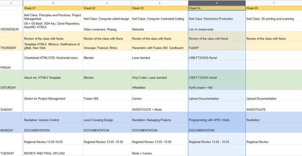
Like every week, my weekly schedule. 😊
I studied electronics during my vocational training, but I always used a trough-hole component. When I discovered the Fab Lab León, I saw that I could create my own boards and use smaller components, type SMD.
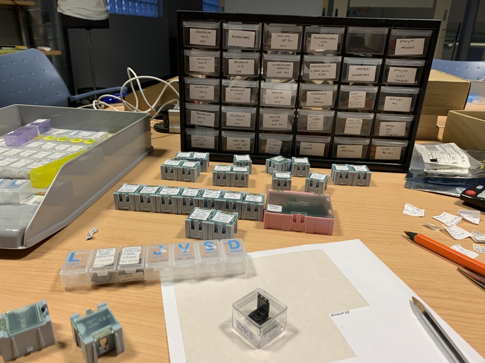
A very important work within the Fab Academy is the inventory. New components are added every year, more modern and others begin to become obsolete. For this, the inventory of the Fab Lab León must be updated; so I help my instructor Nuria what components we need and to order the new ones in boxes. 💪
Group Assignment
The Group Assignment page is at the following link.
26/04/2022
ATtiny402 process in a Board House.
01/09/2025
The machine and the PCB production process
The CNC Milling Machine that exists in the Fab Lab León is the following model.
- Model: Roland MDX-20A
- Software: Mods / Mods CE 😎
- Settings: Detailed in the section “Milling a PCB”
- Specifications: Max. operation area: 203 mm (X) x 152 mm (Y) x 2 9,5 mm (Z), Mechanical Resolution 0.00625 mm/step, Revolution speed 6500 rpm
- Tools: Milling bit 0,4 mm (1/64”); Milling bit 0,8 mm (1/32”)
- Material: FR-1 Printed Circuit Board 75 x 50 mm.
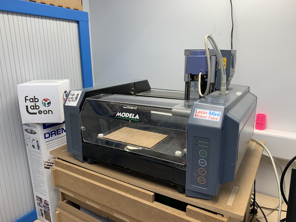
ROLAND MDX-20A MODELA + MODS
20/01/2020
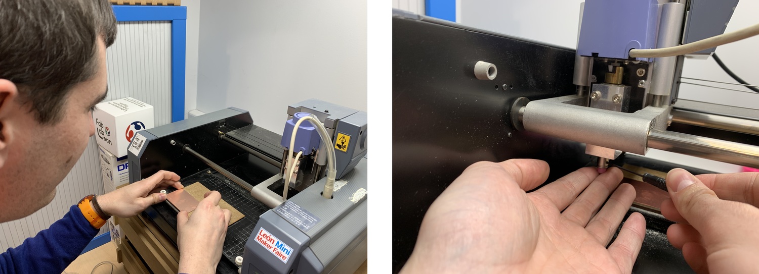
First, I place the new copper board on the spoil board of wood in the machine. For this I use double-sided tape to fix it. It is recommended that it is very straight and well glued, but when we mill it will move and we will lose all the work. When we mount the mill we will only fix a screw and with the rod until the end. When we go to make the Z we go down and when we have about 3-4 mm we stop, we put our fingers as in the photo and we loosened the mill so that it leans on the copper. We tighten the two screws.
In the Fab Lab León until this year, Fab Modules , the old and obsolete version of Mods, had been used. To do this, my instructor Pablo set up a computer with Linux and installed and Mods CE from Fran of The Beach Lab.
To start using Mods, I use the following tutorials: Mods and Mods connection
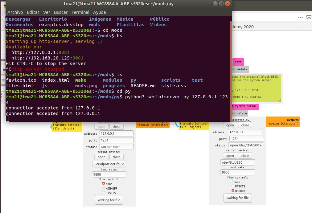
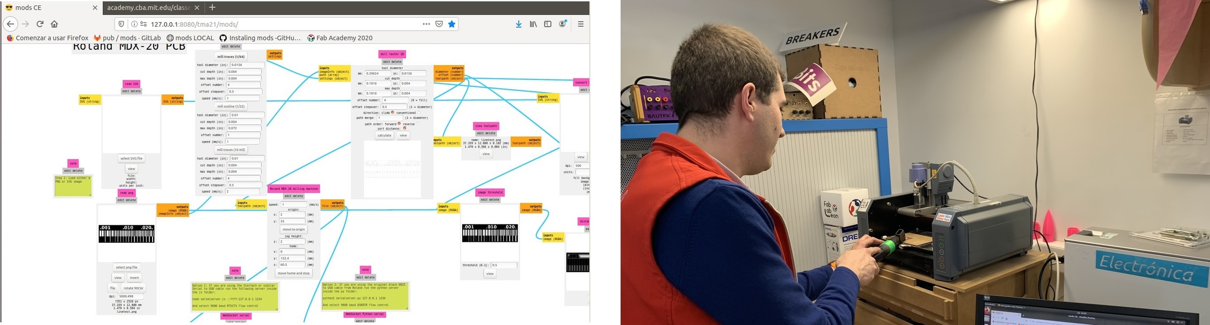
From terminal I open Mods, I connect the Modela to the computer using the original black DB25 cable. In Mods I open the Roland MDX-20 PCB program. At the bottom is the WebSockect Python serial module where we must open it to connect to the Modela. To do this IMPORTANT you have to start the servers in the mods folder: hs start-servers.
Once the port is open, I try to set an X: 1 and Y: 1 origin. And she moves. 🤩
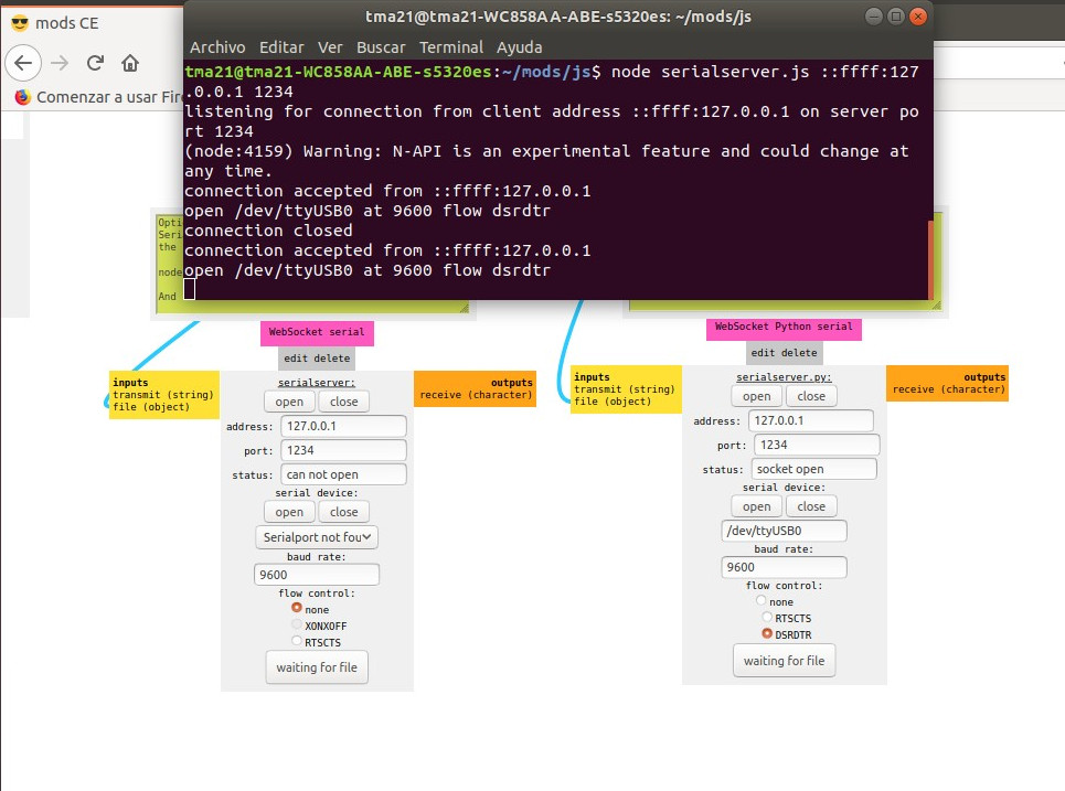
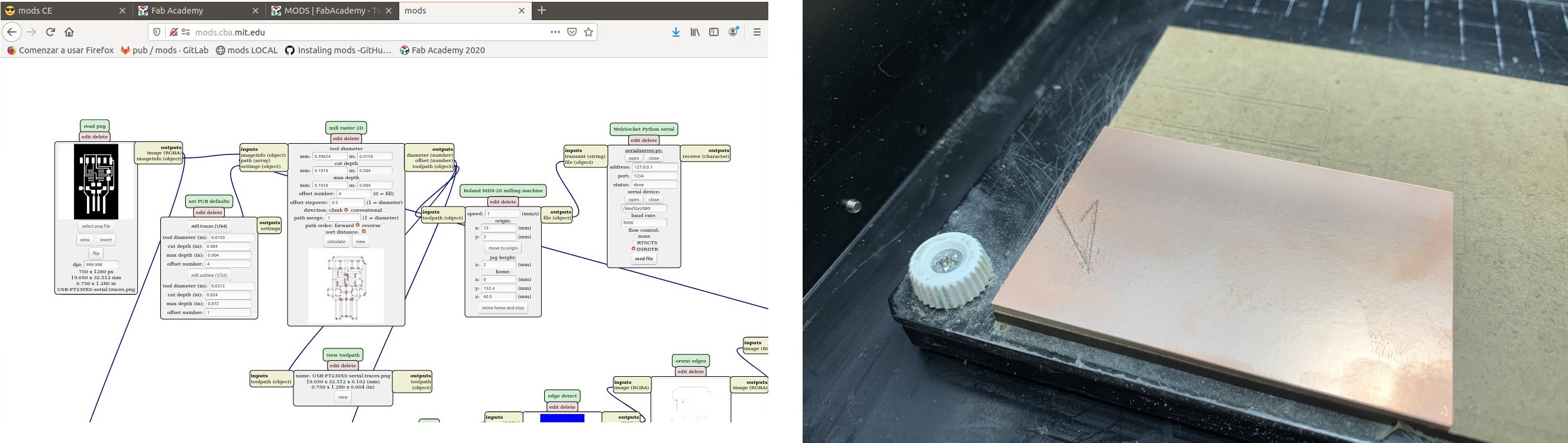
The first test I'm going to do to see if Mods really works is to mill the USB-FT230XS FTDI programmer. To do this I upload the PNG of the traces, I choose the mill 1/64 under the speed at 1 mm / s, I simulate and finally the Flow Control I set it to None. I send it to the machine and start making triangles. Something is wrong. 😣
I try again by changing the Flow Control to DSRDTR and it doesn't work either. Following the threads of the modules, I try to change the Toolpath module and it also does not work and hangs up to the browser. I pass to try the Mods of Neil, the machine is connected, but when you send the work it continues making the triangles. 😭
Nuria informed me that the same thing happened to her years ago, she made triangles and weird routes. Apparently it was cable problem. In the Fab Lab there was another cable a DB25 adapted with a USB, called Startech or similar Serial to USB cable. Thanks Nuria, you are the best. 😇
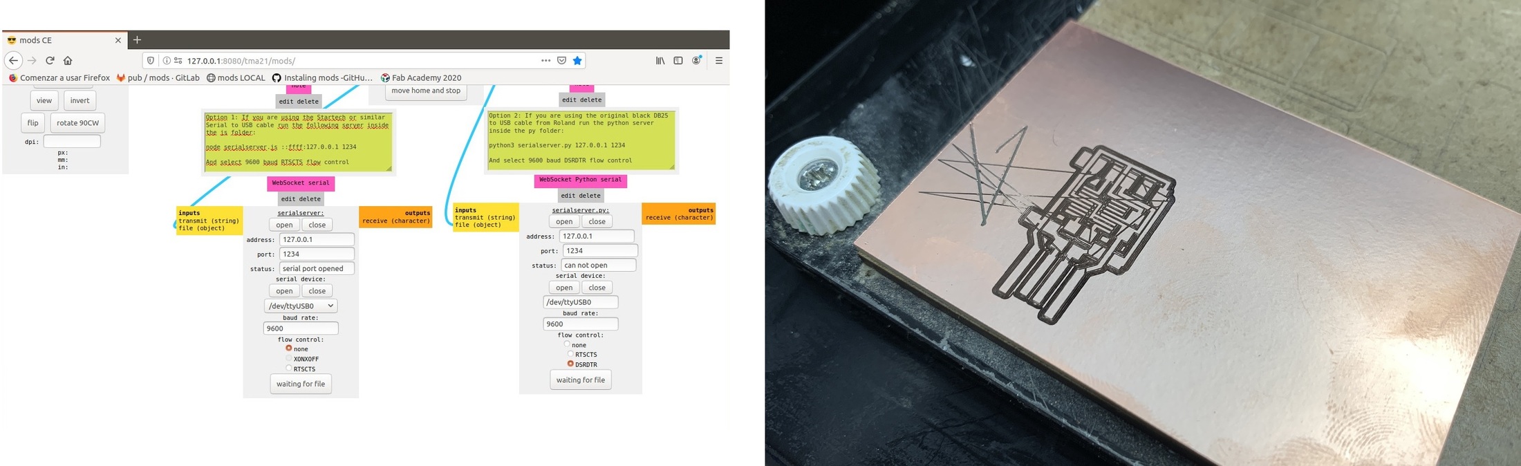
So I disconnect the original DB25 cable and connect the new one, I modify the connection module. Step from Websocket Python Serial to WebSocket Serial. I send the work of the USB-FT230XS FTDI programmer again but with a used mill and it WORKS
21/02/2020
After the day before I managed to configure Mods, make him communicate with the Modela and do a test; It was time to take action. So I start again to send the work to the Modela and what is my surprise that with the cable that worked yesterday at the last time it gave me problems again, rare trajectories again. 😣
I review all the steps in the tutorial again and I realize that I am configuring the port with the Serial-USB cable with the WebSocket Python Serial configuration. OMG 😱 And all this for not reading the steps well. The syndrome of TL, DR or RTFM. Nuria and I came to the conclusion that I was not doing well yesterday, except once I get it right. 😪
Once the error of today and yesterday has been detected, I configure the original DB25 cable with the python server and it works. 😌
To learn a little more about the Roland MDX-20A, I'm going to take the line test that Neil taught us in class.
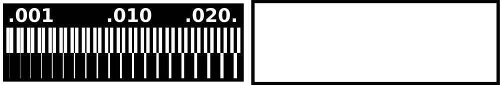
So I send the trace width test, at the point X = 2, Y = 35 and with a speed of 1 mm / s for the milling cutter of 1/64. Once I finish milling the interior strokes, I vacuum the FR1 board and replace the mill with that of 1/32 with the same parameters X = 2, Y = 35 and speed 1 mm / s. Being a different mill, you have to do the Z again.
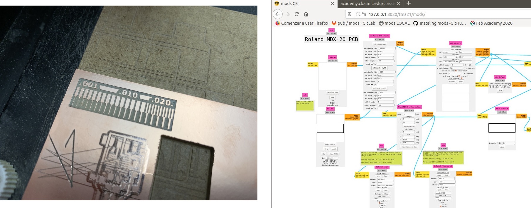
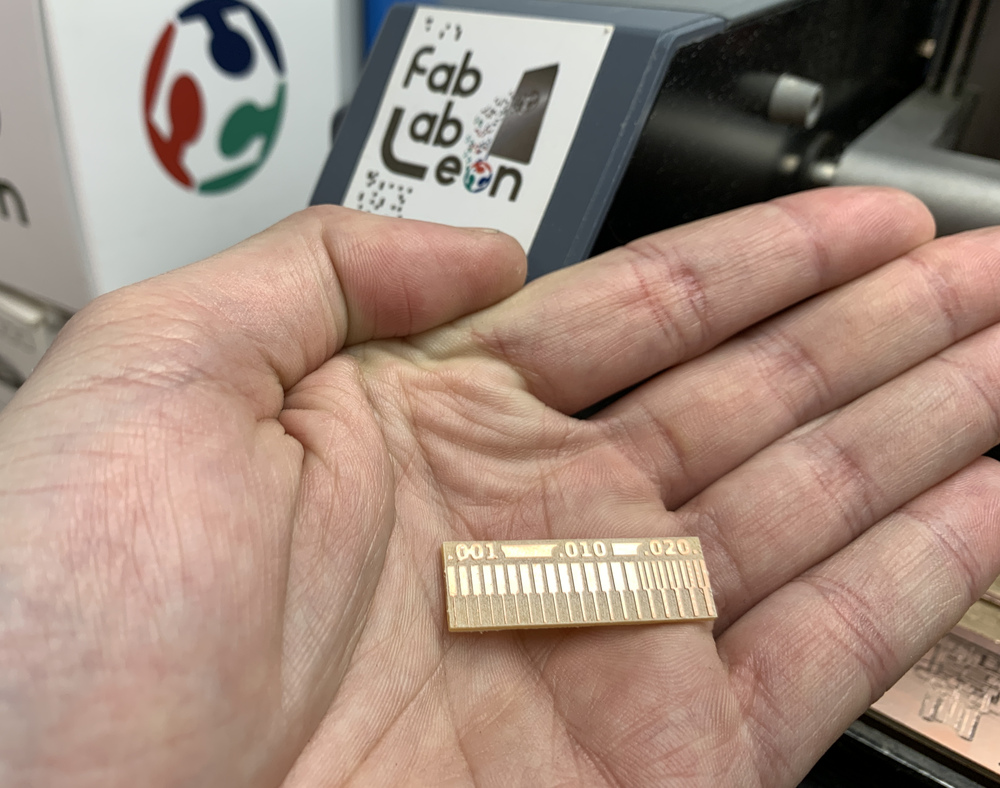
And this is the final result of the test, the fine lines of the end are maintained, which are as fine as those of the UPDI (USB-Serial FT230X).
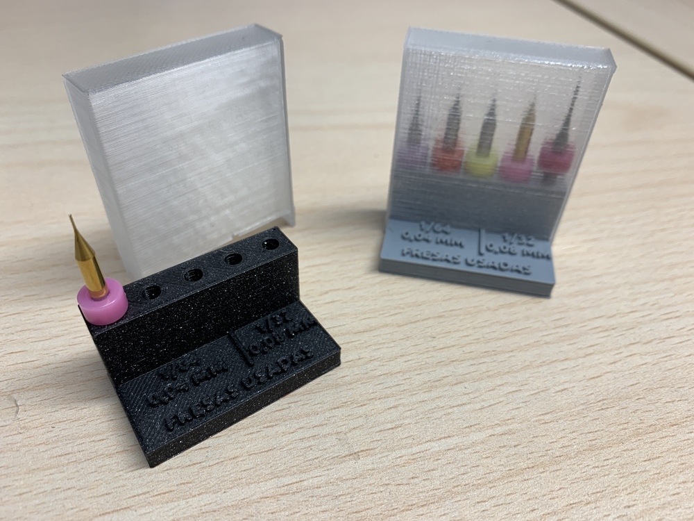
USED MILL SUPPORT
When we are milling several PCB we always use two types of mills (1/64 or 1/32). And as they are already used, so as not to mix them with the new ones I have designed a support to keep them. I leave here both files, the support and the protective case. Support and Protective case
UPDI (USB-Serial FT230X)
After the setup of Mods, I'm going to make the programmer for the new Attiny; the USB-Serial FT230X programmer. The first thing I do is download the PNG files that contain the inner and outer tracks.
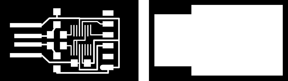
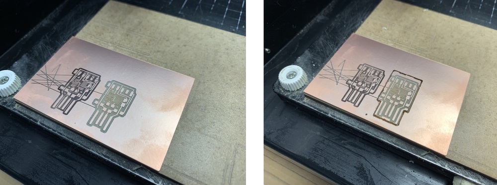
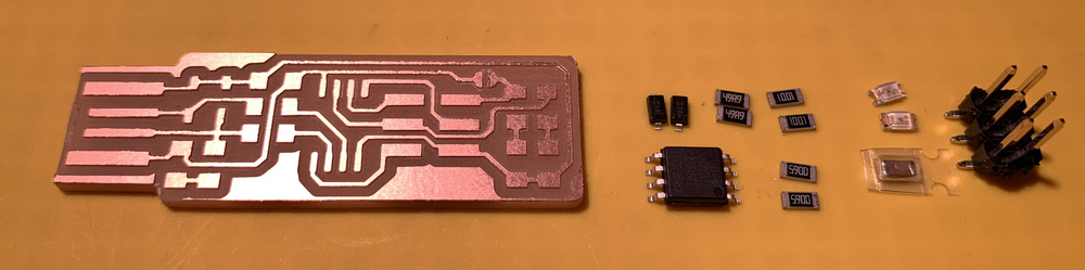
I begin with the internal milling of tracks with the milling cutter of 1/64 (0.04 mm) and a speed of 1 mm / s so as not to break the mill. For the outside I use the mill of 1/32 (0.08 mm) and a speed of 1 mm / s. This is the end result of milled PCB and components. REMEMBER to remove the small piece of copper on the tip of the USB with a cutter.
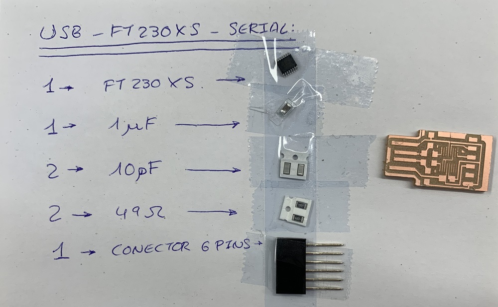
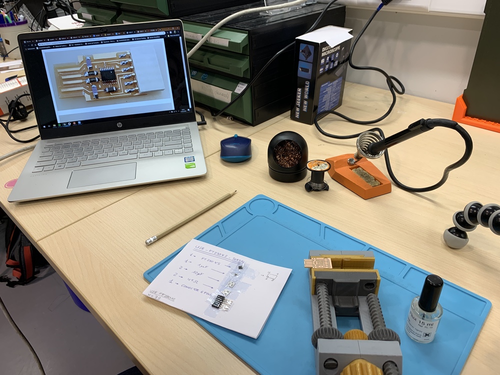
This is the end result of the milled programmer.It is important to have the components well identified, because for example the capacitors are the same externally and we can easily confuse them, so it is advisable to make the list on paper and stick them with tape.
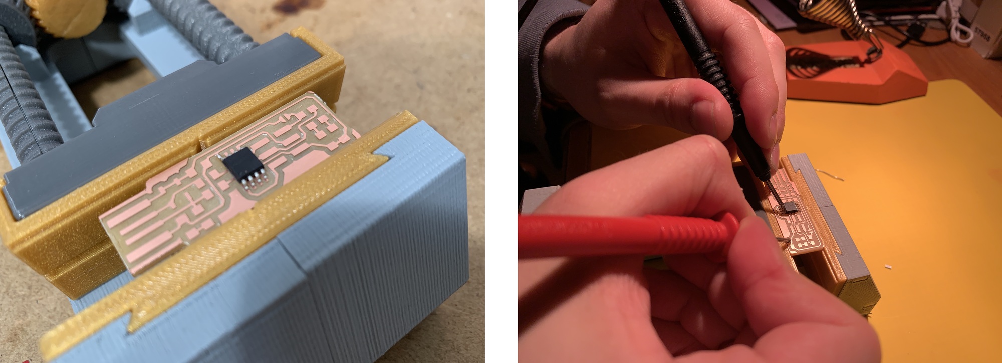
When we have to weld small components, the ideal is to have a well-lit space and that we can work well. With a small 3D printed vise fastened the PCB. With the scheme and the photos on the computer and a lot of patience and pulse I start welding.
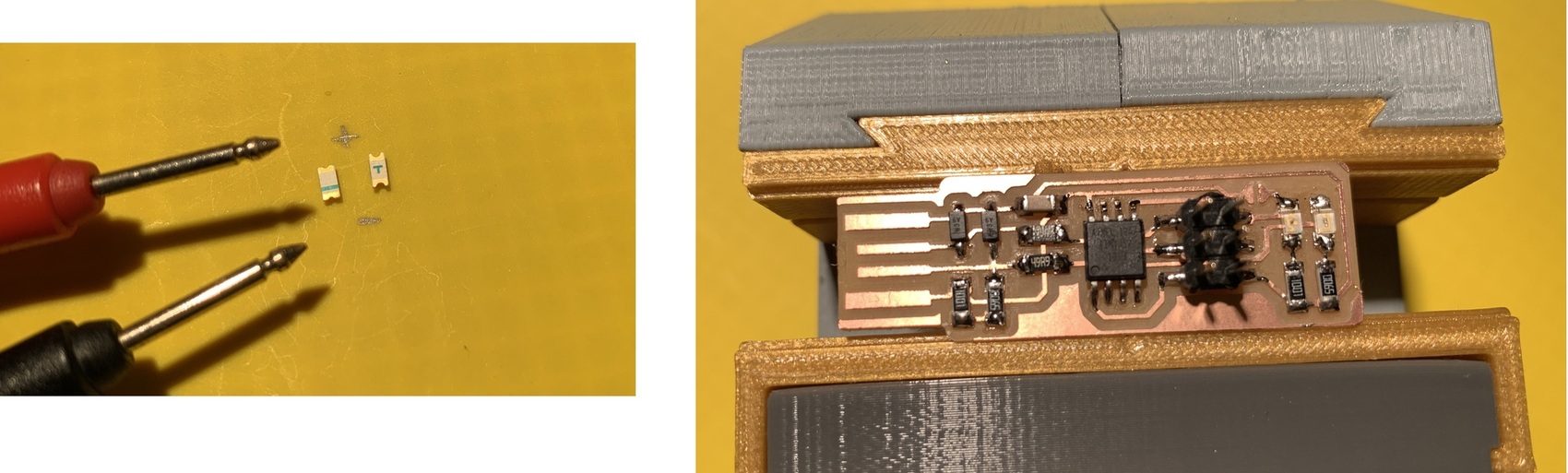
The first thing to weld is the driver and then the smaller components and the center out. I have never welded a component with pins as thin as the FT230X. 😱 Nuria recommends that I apply Flux to ensure that tin is well taken. As I explain in the Neil class, the ideal for these components is to tin all the pins, and with a desoldering iron remove the tin you don't need and it works.
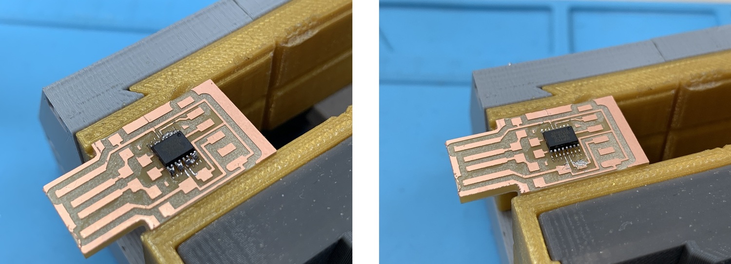
Once the driver is welded, I weld the other components. For the FTDI pins I recommend bending them a little so that it rests the connector on the board.
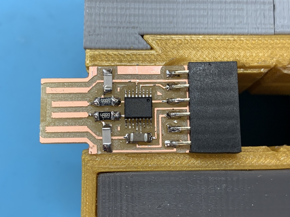
Here a small timelapse of USB-Serial FT230X welding.
Once the board is finished, I try to connect it to the computer to see if it recognizes it and does not. Something is wrong, so check it out. 😪
22/02/2020
After turning it around all night it could be, and writing in the Telegram Regional Review group where Fab Lab BCN is, Santi and Eduardo Chamorro recommend me to check the driver welds. Thank you guys. So with the polymeter I check all the tracks and I see that there is a lack of continuity in the USP and R2 pin (which was the first one to weld to hold the driver) and the 3V3 pin with VID. Welding looks good with the magnifying glass, but does not make contact. So I re-tinned and removed the excess (here I have to sacrifice the capacitor).
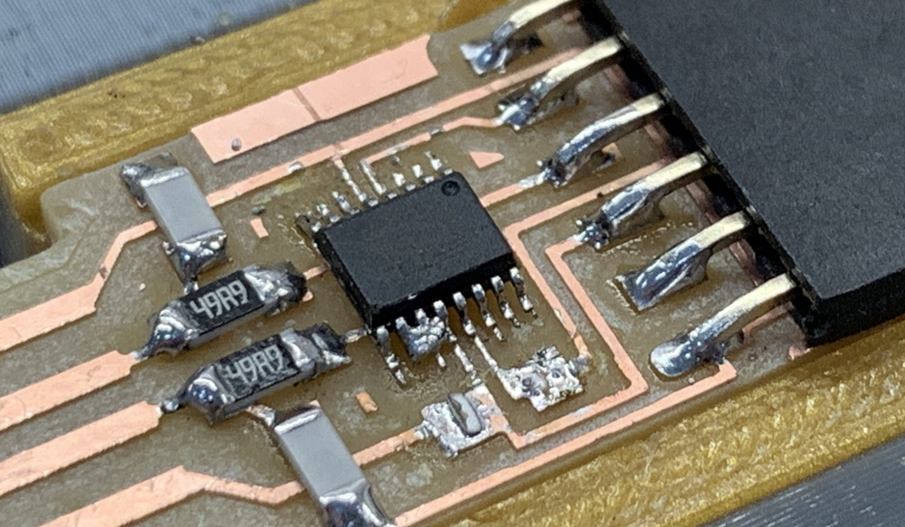
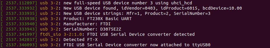
Once the USB-Serial FT230X is repaired, I connect it to the Nuria Mac and recognize it. Its serial number is D3075E2Z.
As it lacks space for good USB contact, I design a 3D printed case. Here is the file in case anyone needs it.
Vinyl copper. Hello ATtiny 412.
I've always wanted to make an electronic circuit with copper vinyl. I have seen Nuria use it in the Fabricademy and the Poderosas in her small projects and I love it.
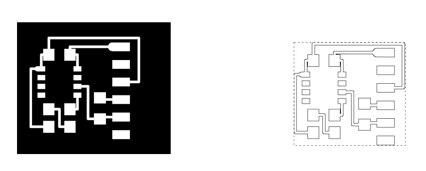
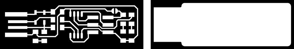
I need a board to check the USB-Serial FT230X programmer that I have manufactured. The first thing I do is download the PNG files of the Hello ATtiny 412 of the week of Electronics Desgin. In this case I just need the traces. I open Inkscape to vectorize the image and take out only the vectors; I save it as a PDF.
After vectorizing I import it into Rhinoceros where I am going to cut it with the Roland GX-24 vinyl cutter I used last week. Nuria has documented the parameters for copper vinyl cutting, so I can start testing on estimated values. Thanks Nuria. 😘 I found the right part when I had already done the board. 😅
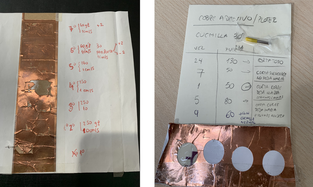
I use 3M™ Copper Foil Tape. Start testing with 40 gr of force, 1 mm / s of speed and +2 of the pen force with a standard 45º blade. The test performed well, but the board lifted all the copper. I keep varying different parameters and nothing. I decide to change the blade for a 30º and the head that has regulation. I modify the force parameter to 30, 40 and 50 gr of force. Also the speed of 1 to 5 cm / s. I note that the best is the 40 gr that cuts but not quite (at 30 it doesn't cut and at 50 it rises). The final parameter is with the blade of 30º (yellow) 40 gr of force and 1 cm / s.
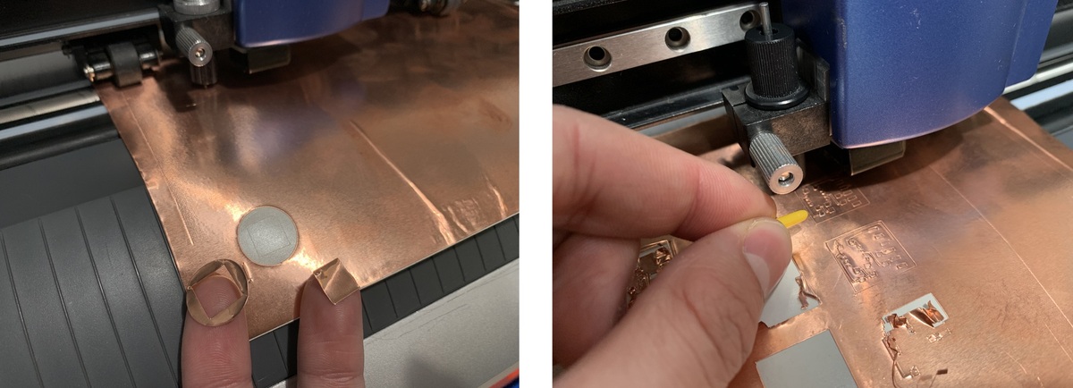
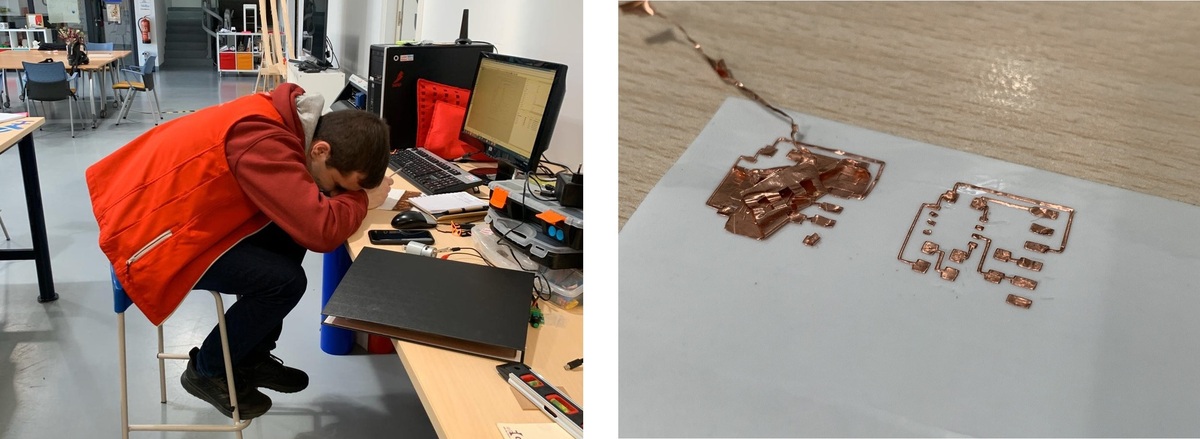
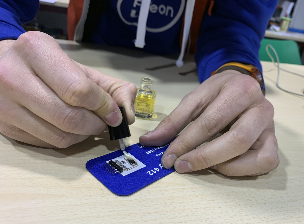
Once the copper has been cut, I try to peel it directly from the tape. And it's complicated that it doesn't break any lines. 😅 So I remove the entire square and transfer it to 3M ™ Epoxy Film Electrical Tape.
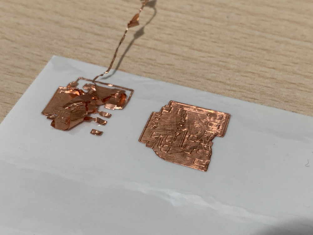
So little by little I start to remove the copper that I don't need to leave the board ready. The previous photo was taken by Nuria because of the difficult position I had in the chair and the laughter of the funny moment 🤣 ; because otherwise you have to have fun with the Fab Academy. 😄
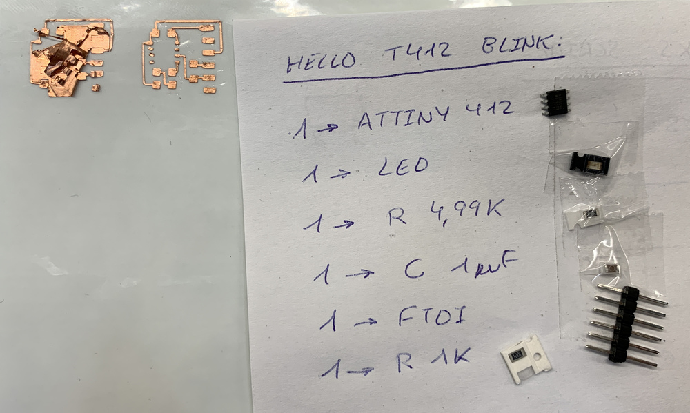
Once the board is ready, I look for the components of the Hello ATtiny 412, to start placing them.
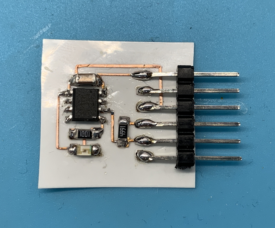
Here is a small video of the process, from cutting with the vinyl cutter, peeling and welding of the components. 😃
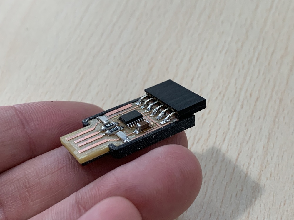
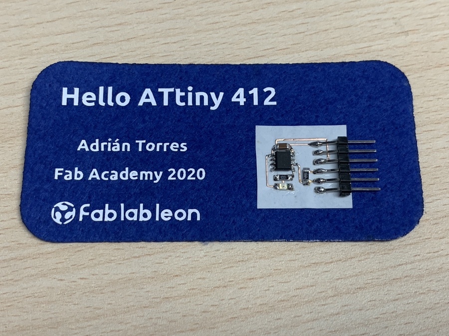
And this is the final result of my first board welded on copper vinyl. It's amazing. 😍
Nuria explained that I could now apply this board to a flexible surface, such as polypropylene or fabric. Thanks Nuria.😘 So with felt that it is a fabric based on pressed fibers. I cut it with the laser cutter and with the vinyl cutter and vinyl textile make a badge of the Hello ATtiny 412.
Here I leave the Hello Board line archive in SVG
Programming the Hello ATtiny 412 with the UPDI (USB-Serial FT230X)
23/02/2020. Windows.
Using the new UPDI programmer (USB-Serial FT230X) I am going to program Hello with the ATtiny 412 that I created with copper vinyl. To do this, I connect the board as follows.
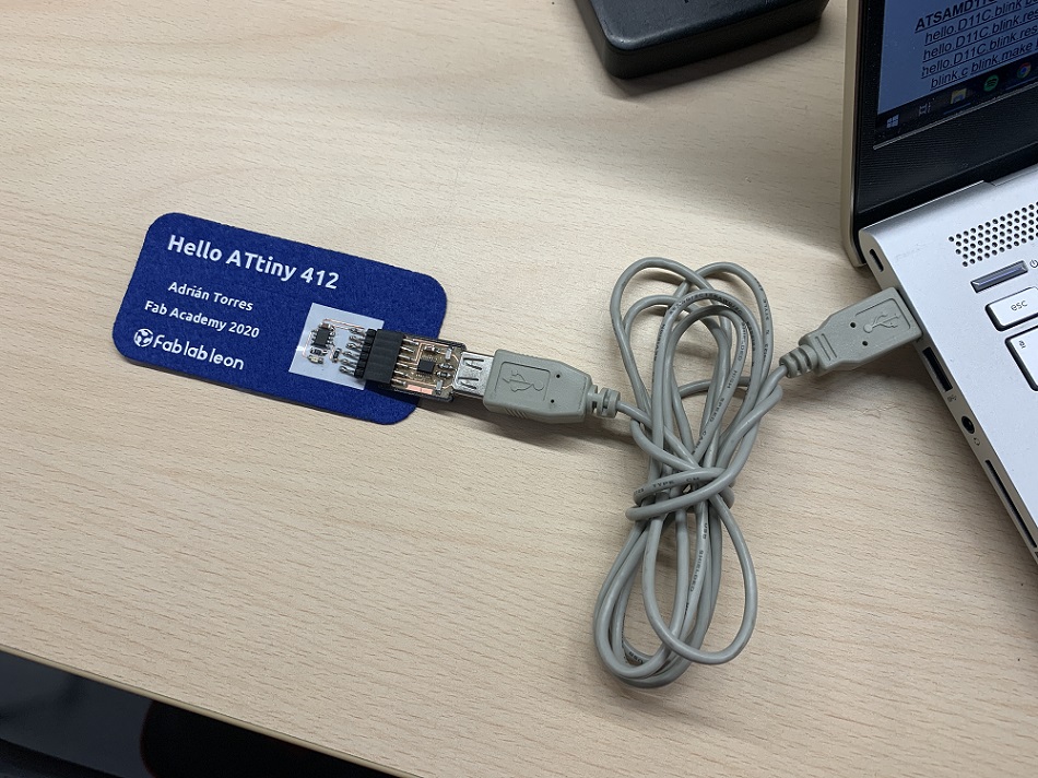
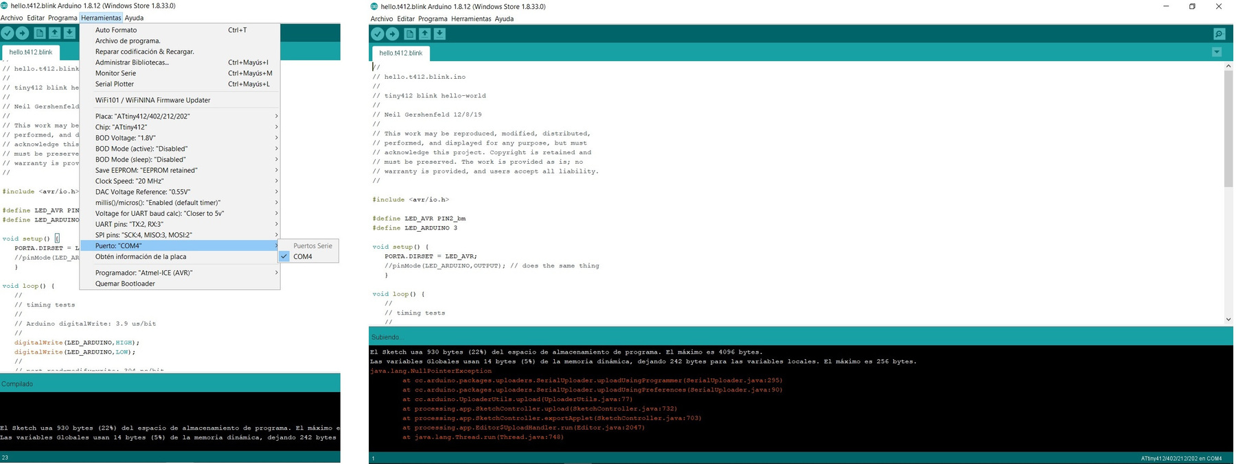
Although it is not this week, I try to program Hello with the program that Neil has as an example. For this I use Arduino, I connect the programmer and recognize it in the COM4 port. I set up the Arduino for the ATtiny 412 (20MHz internal Clock) and as Neil puts in the example video with the Atmel-ICE programmer (AVR). I compile the program and charge it. It keeps going up and several errors appear in the Arduino information screen.
25/02/2020
As I have seen that on Mac I needed to know where the .hex file is, I look for it in Windows and it is in the following path: C:\Users\Adrián\AppData\Local\Temp\arduino_build_198605 I copy it and put it in the folder "pyupdi". With Gitbash I execute the same command as in Mac and in Windows python3 pyupdi.py -d tiny412 -c /dev/ttyUSB0 -b 19200 -f hello.t412.ino.hex -v
I still can't get it, I get an error in git bash or in terminal running python3; I don't know if it will be something of the permits, I don't know. Keep investigating.
24/02/2020. Linux.
As in Windows I did not manage to program Hello, I will try Linux. I follow the tutorial that Pablo taught me that they used in the Bootcamp in India that Santi from Fab Lab BCN created.
- 1. For this I install Arduino and download the blink.ino from Neil. I select the ATtiny 412 and 20Mhz internal Crystal microcontroller. I check it, compile it and save it (save it in .hex and .ino).
- 2. I download "pyupdi".
- 3. Open terminal. Install dependeces: pip3 install intelhex pylint pyserial
- 4. I connect the USB-FTDI to the Hello ATtiny 412.
- 5. I run dmesg -w
- 6. Connect and disconet the ftdi cable and take note of the "port name" where:
- 7. Go into the "pyupdi" folder.
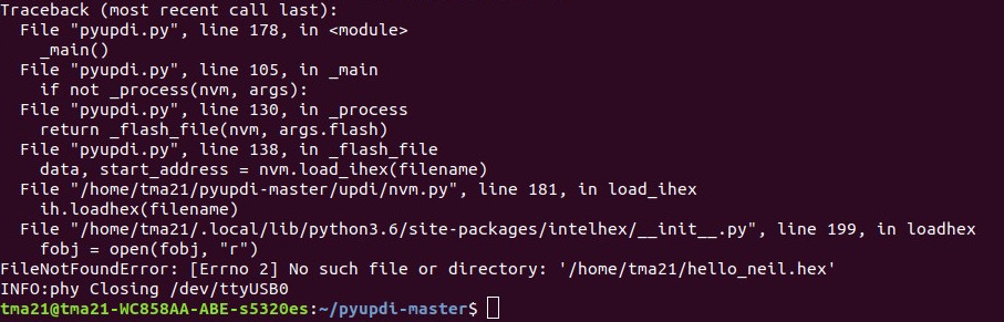
- 8. Program the board using python -> run sudo python3 pyupdi.py -d tiny412 -c /dev/ttyUSB0 -b 19200 -f Hello_neil.ino.hex -v
And here I get the following error, which does not locate the .hex file even by putting it in the "pyupdi" folder.
25/02/2019
The error was that I was trying to load the .hex folder and not the .hex file. I also have to look for it in the temporary Arduino folder, copy it and paste it in the "pyupdi" folder. And it works, here a video. 💪
24/02/2020. Mac.
After trying it with Linux, Nuria got me to try it with her Mac, because she had also made a Hello Board with the ATtiny 412.
- 1. You have to have the .hex file inside the "pyupdi-master" folder (the one that we download at "pyupdi".)
- 2. We have to know exactly where that file is, so we move through the terminal to the pyupdi folder.
- 3. We list the devices with ls / dev / tty*
- 4. My programmer is tty.usbserial-D3075E2Z We copy it.
- 5. We run: sudo python3 pyupdi.py -d tiny412 -c /dev/tty.usbserial-D3075E2Z -b 19200 -f hello.t412.blink.ino.hex -v
It works, a great job of Nuria and mine. Thank you Nuria 😊 A video of the load and operation.
Nuria wanted to change the blink speed, so she modified the delays, but she didn't save the .hex extension. To do this he had to configure the Arduino so that it only compiles and the file .hex .elf .bin .eep and .lst saves it by default in a temporary folder. So you have to find it and take it back to the "pyupdi" folder to load it again.
As the board made of copper vinyl works, I decide to apply nail polish so that the tracks do not come loose and hold the components.
FabISP of Brian
The second programmer I'm going to try to make is Brian's. In this link is the tutorial that I will follow.
For this, the first thing I need is the PNG files for the traces and the board outline. Then on a sheet I place all the components that I will need with tape..
I begin with the internal milling of tracks with the milling cutter of 1/64 (0.04 mm) and a speed of 1 mm / s so as not to break the mill. For the outside I use the mill of 1/32 (0.08 mm) and a speed of 1 mm / s. This is the end result of milled PCB and components. REMEMBER to remove the small piece of copper on the tip of the USB with a cutter.
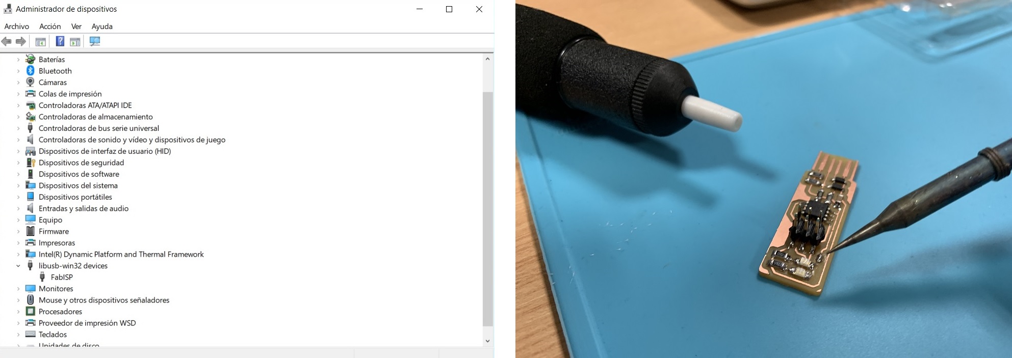
Now begins the part that needs more patience and pulse, weld SMD 1206 components. As my instructor Nuria has told me, the smaller and center components are welded out, leaving the larger ones for the end. Thank you, Nuria. 😘 The first to weld is the Attiny45. A small point of tin on the first track and we will heat it to join the pin of the Attiny45. Once all the pins of the Attiny45 are soldered, I check the continuity of the tracks with the polymeter.
Once the Attiny45 was well welded, I started welding the resistors and the LEDs. A small trick to identify the polarity of LEDs is to use the multimeter and paint on paper, which is the positive and the negative. I check them with the polymeter once soldiers. Then I solder the capacitors (they don't have polarity), the two Zener diodes and the resistors. Finally I solder the 2 x 3 male ISP connector. Remember to tin the small bridge.
Here a small timelapse of FabISP welding.
Program the FabISP
As I use Windows I will follow the steps in this tutorial to program my FabISP.
The first thing I do is download an Atmel AVR Toolchain, the AVR 8-bit Toolchain version v3.62 - Windows. Then the GNU Make and the AVRDUDE. I have to modify the path of my computer. It is very important, but it will not work.
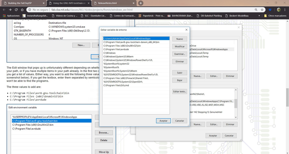
Then we install the Zadig driver. Once we have all this, we go to the Git Bash terminal from which we will program the FabISP. We plug the "FabISP mother" to our computer and our FabISP to an external power supply.
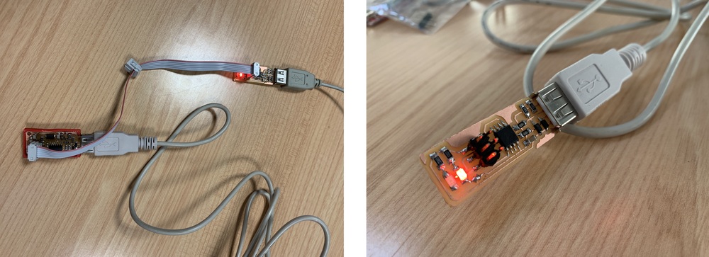
First we will do "make flash", then "make fuses" in Git Bash. Then we disconnect the "FabISP mother" from the computer and connect my FabISP. The new device appears in the Control Panel.💪 Then you "make rstdisbl". Once the installation is completed and the jumper removed the FabISP is ready!!
Programming the Hello Light with the FabISP
Nuria give me a Hello Board with two Led´s. So I'm going to load a program with Arduino that makes a Led gradually increase or decrease its luminosity. The board had a blink loaded on a Led. I connect the Hello Light with an FTDI-USB to an external power supply and through the ISP pins I connect it with the flat cable to my FabISP.
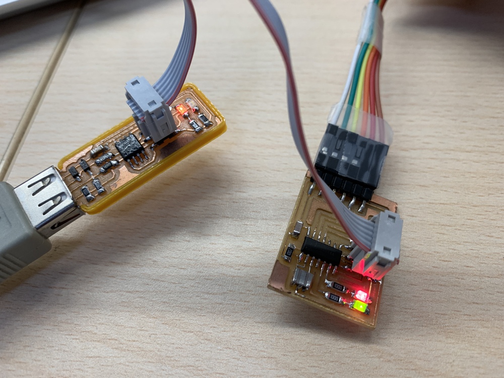
Once I have configured the Arduino for the ATtiny44 and I have the program I charge it. Here is the video of the process and how the Hello Light works.
As for the other programmer, for FabISP I also designed and printed another case in 3D. Here's the file.
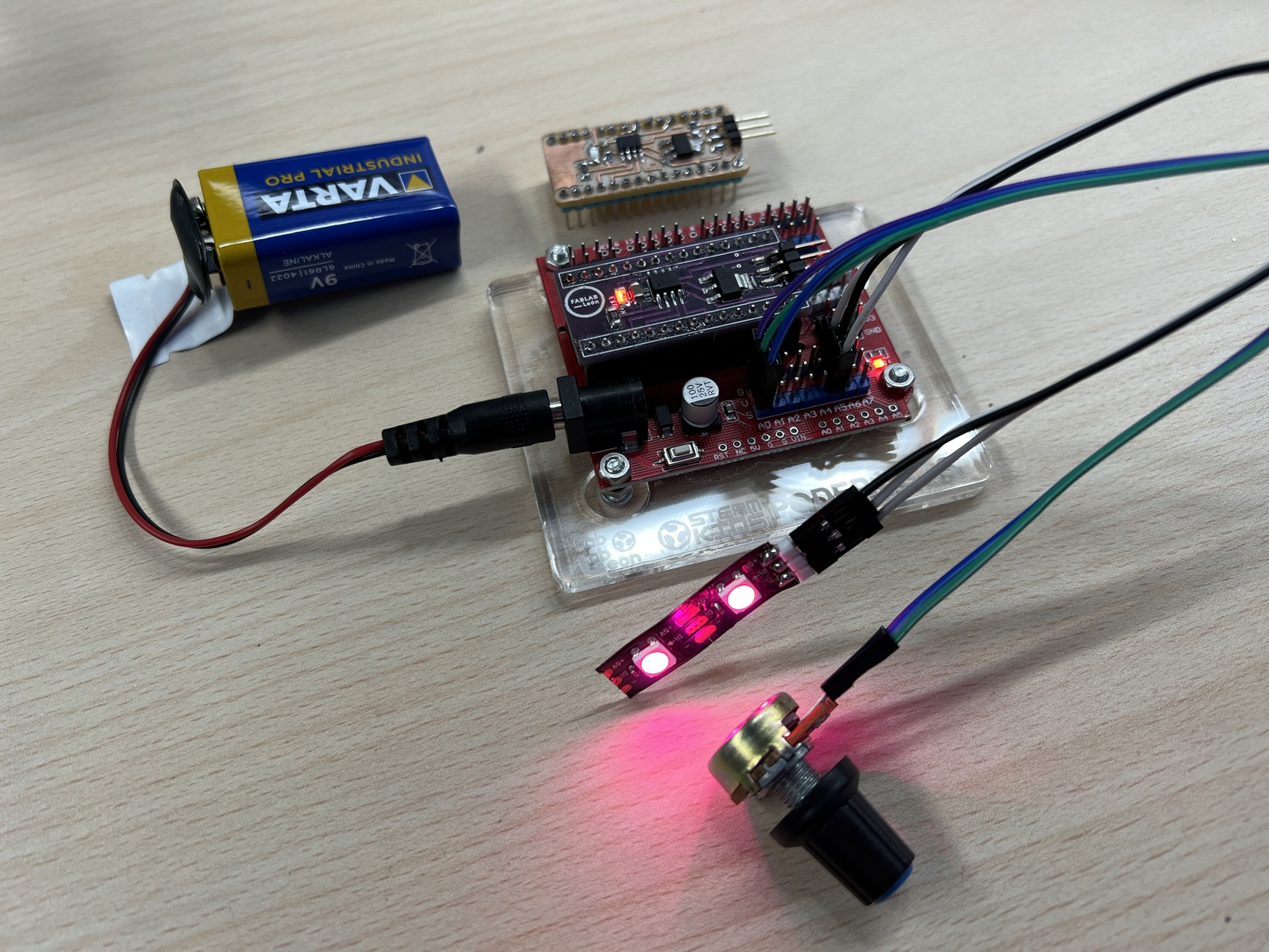
Board house
Given the situation of out of stock and the increase in the price of the Arduino Nano, at Fab Lab León we thought of designing our own programmable board for the projects of the Young Makers.
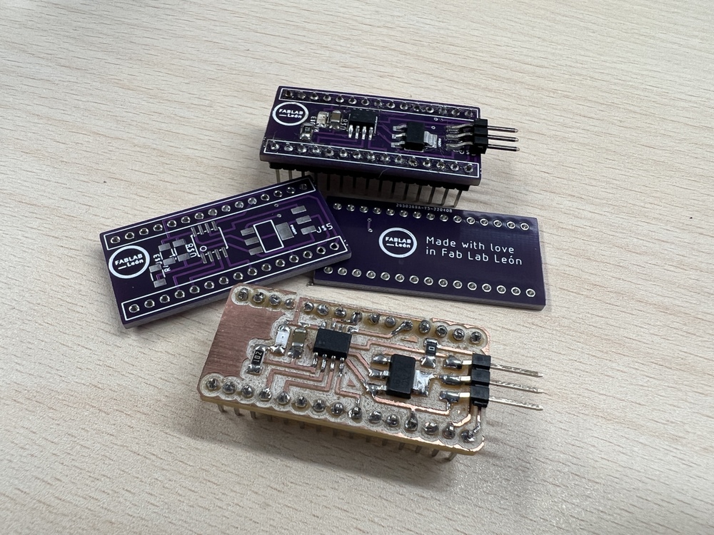
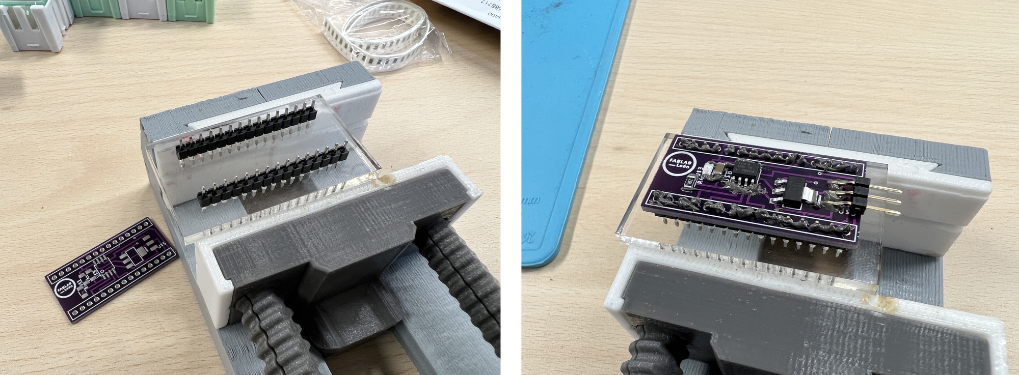
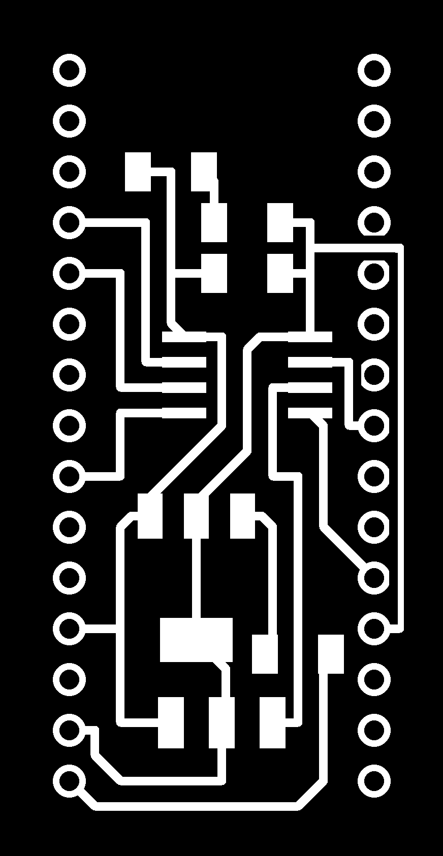
Once the design was tested by milling on the Modela MDX-20, I sent the Gerber to the JLCPCB factory. Afterwards, with the Solder Paste and the Hot Air technique, I solder the components. Using acrylic, I create a base to solder the pins.
Now we have a custom and cheaper board to be able to attach it to the Arduino Nano Shields so that Young Makers can use it in their projects.
Here you can find the files
Genmitsu Cubiko CNC Router
At the beginning of 2025, a Kickstarter was launched with the Genmitsu Cubiko CNC Router. I bought one to see if it was a machine that could replace the Roland MDX 40 so I could make boards and mill wax molds for molding and casting. After several months of waiting, the machine arrived in August.
If you want to see how this CNC milling machine works in the wax mold milling section, check out this link.

Inside the machine comes a kit with different tools with wrenches to tighten the spindle, the cable to make the height map, and various types of end mills and drill bits. It comes with various clamps to hold the material and a USB port with an SD card for uploading files. The machine can also be connected to a computer via USB.

A small improvement I have made is to create a 2mm MDF martyr so I can mill without damaging the bottom. You can find the file here to cut with the laser. Using four screws that come with the kit, the martyr is fixed to the base of the machine.

Next, I use clamps to secure the board to the martyr. Be careful, the clamps don't conduct electricity (because they're coated), and the first few times the height map failed and broke several of my end mills.😭😭 So I use a clamp and press it against the board and the height map connector; I'm looking to improve this system.

Next I tested the machine with various end mills and Mods CE.
V-bit
In this case I use a 20-degree V-Bit from the Sainsmart brand. To do this I place the V-bit in the collet, tighten it with the two wrenches and move the machine to make the X/Y 0.0.

First we will set the X=0 Y=0 of our work. In the "Prepare" menu, you'll find the following arrangement of elements to move the machine (if this is your first time, I recommend doing it empty without the end mill). In the orange box, you can change the machine's movement speed from 0.01, 0.1, and 1. For some settings, it's advisable to change the speed. Once the speed is set, we'll move the machine using the dashed red buttons. When we have points X=0 and Y=0, we'll press the button I've marked in blue.

Once we have X=0 and Y=0 we move on to making the Height Map. In this case I follow the instructions of Sainsmart to create the Height Map (you have to connect the crocodile to the end-mill). I recommend making a Height Map slightly larger than the board we're going to mill; and the more control points you have, the more precise it will be, but it also takes a while. In my case, I usually choose 6 x 6 points.

NOTE: The height map will be saved for all work done on that board. If you change the board, you must repeat the previous steps.
ATTENTION: Once finished, remove the crocodile from the end mill.

Now we move on to Mods CE. We'll select the G-Code Mill 2D PCB menu. First, we load the PNG and then select the V-bit strategy to create the traces. Now we move on to Mods CE. We'll select the G-Code Mill 2D PCB menu. First, we load the PNG and then select the V-bit strategy for creating the traces. I change two small values; in my case, the V-bits are 20 degrees, and then I want an offset number of 4 to make the traces cleaner. The GCODE is automatically saved on our computer.

Well, now it's as simple as taking the file and saving it to the microSD card that comes with the machine.If you notice, the machine is elevated 5 mm in the Z axis. That's the Z axis. Now, in the "Prepare" menu, click Files and select the file. To start the file, we must place the casing and it will ask us for the speeds; in my case, for this V-bit, I like to set the spindle to 90%. Next is the Play button.


The machine starts up, and one advantage is that the light lets you see how it's working at all times. Once the machine is finished (it has a timer), we remove the casing, vacuum up the shavings, and replace the end mill with the 1/32 for the cut. It looks spectacular.

Now, to change the end mill, I raise the Z position, remove the V-bit, and attach the 1/64 milling cutter. I've lost the Z position, but that's fine. I slowly lower the Z position until the end mill rests on the board. If I have the Z position, I press the ZS button (this will return the end mill to 5 mm and maintain the height map parameters).

We have the machine ready, but we need to create the file in Mods CE. In the same G-Code Mill 2D PCB module, we import the file for the interior. In this case, I choose the "mill outline 1/32" module. We save the file to the microSD card.

Once on the card, go to the "Prepare" -> Files menu and launch the selected file. In this case, set the speed settings to 100% and press Play. And our board is finished.

Ball Nose Tapered End Mills
Miriam showed me these Ball Nose Tapered End Mills a while ago, and I love them. They don't break and last a long time. In this case I use the model Cutting Edge Length: R0.25-15-D3.1-TiAlN.

In Mods CE the parameters I use are the following for milling the traces.

This is the result: clean, perfect traces. To cut the board, I use the same end mill seen above.

Files
Find below the files that I made for this assignment.