

Index
Introduction
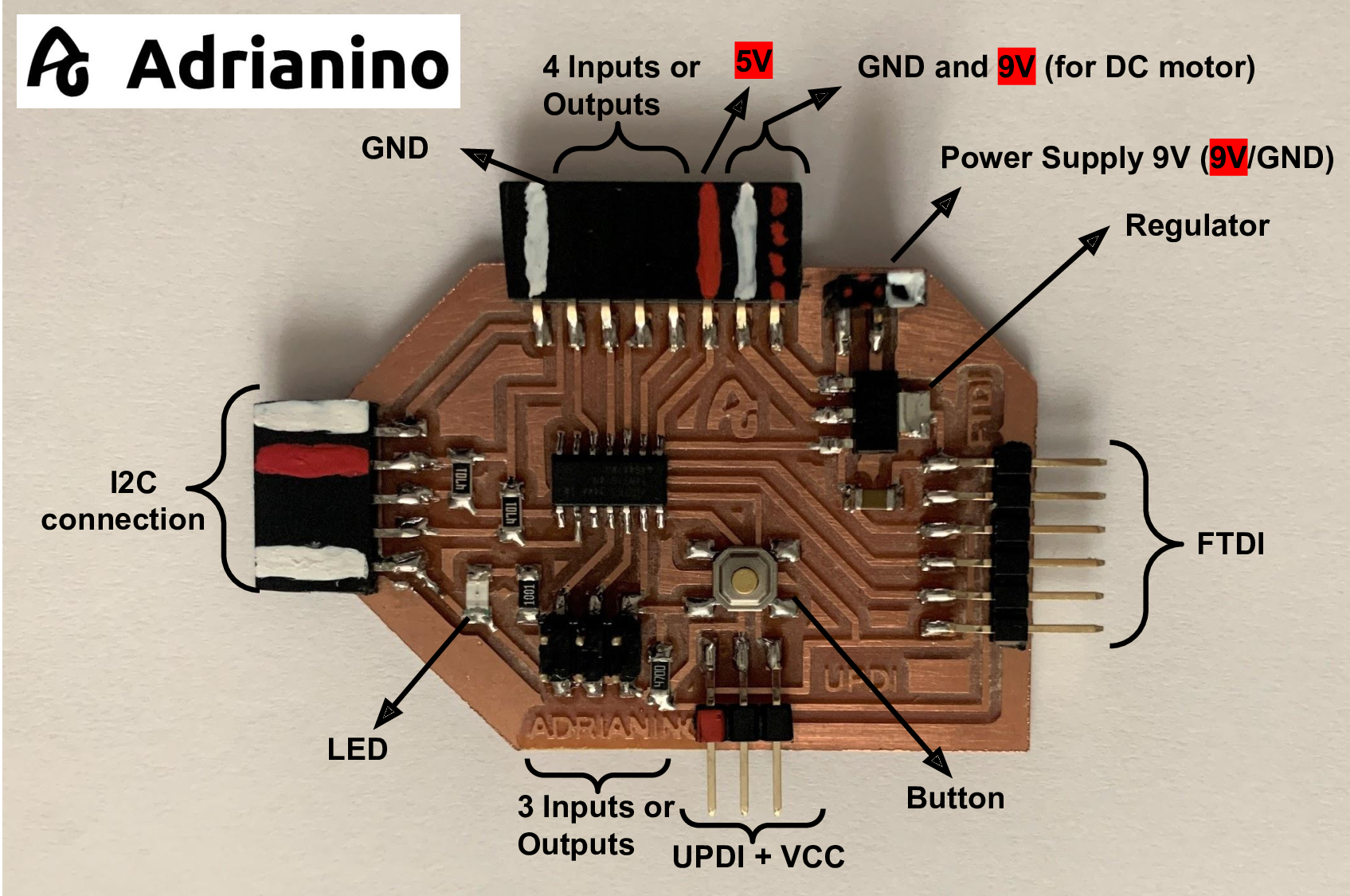
The following project was born with the idea that electronics is very easy to learn and modular at the same time. Although I have already finished my Fab Academy, I am still researching. Speaking with my instructors Nuria and Pablo, I told them that I wanted to continue working on the Hello World project, but I was not satisfied with making a board for each sensor or actuator.
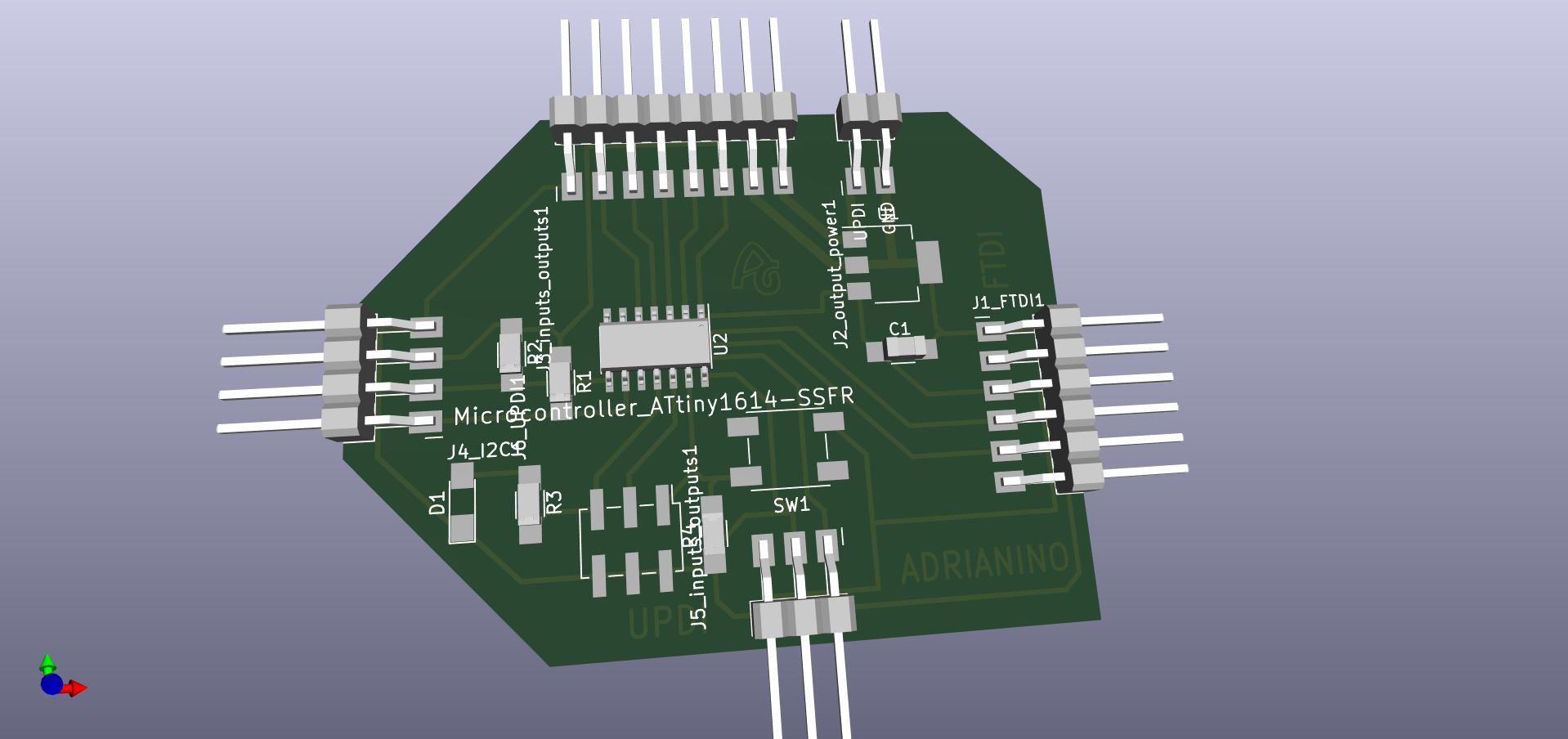
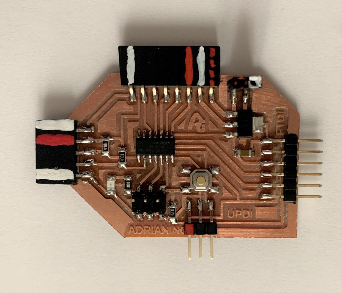
So I decided to make a board with the ATtiny1614 or ATtiny1624, where I could use the maximum pins for the inputs or outputs; that had external power; I2C connection. The idea is that a student can test as many sensors as possible, become familiar with electronics and programming little by little. And the Adrianino was born.
Furthermore, I wanted to go one step further and place a VCC pin next to the UPDI programming pins, which I will explain later on how it works. This version of Adrianino has been updated for the new Serial-UPDI converter.
Features
- This board has FTDI and UPDI + VCC connection to program it without the need for external power (or the FTDI).
- It contains a voltage regulator to power the board with a power supply (9V battery).
- It has another 9V power connection to for example power a DC motor driver.
- Then there are 4 outputs or inputs with VCC and GND on each side to be able to connect different inputs or outputs.
- On the left there is an I2C connection to connect an LCD, OLED or a sensor that uses this communication.
- There are 3 outputs or inputs at the bottom and with a GND pinout.
- There is an LED and an integrated button, which will help us to test that the microcontroller works with a simple program.
- Through the FTDI connection we can read the data from the different sensors through the Serial.
Datasheet
The Adrianino is prepared to use the ATtiny1614 or the ATtiny1624 as a microcontroller.
ATtiny1614
As we have looked at the graph, there are more microcontrollers within the tinyAVR® 1 family. Another ATtiny I use is the 1614. I combine the Datasheet image with the one from the SpenceKonde website on the ATtiny1614.
- 14 pin package.
- Two internal clocks 16 and 20 MHz.
- 16 KB Flash Memory.
- 256 B EEPROM.
- 2 KB SRAM.
- Maximum voltage: 6V; minimum voltage -0.5 V.
After looking at the basic features, you will find the pinning of the microcontroller.
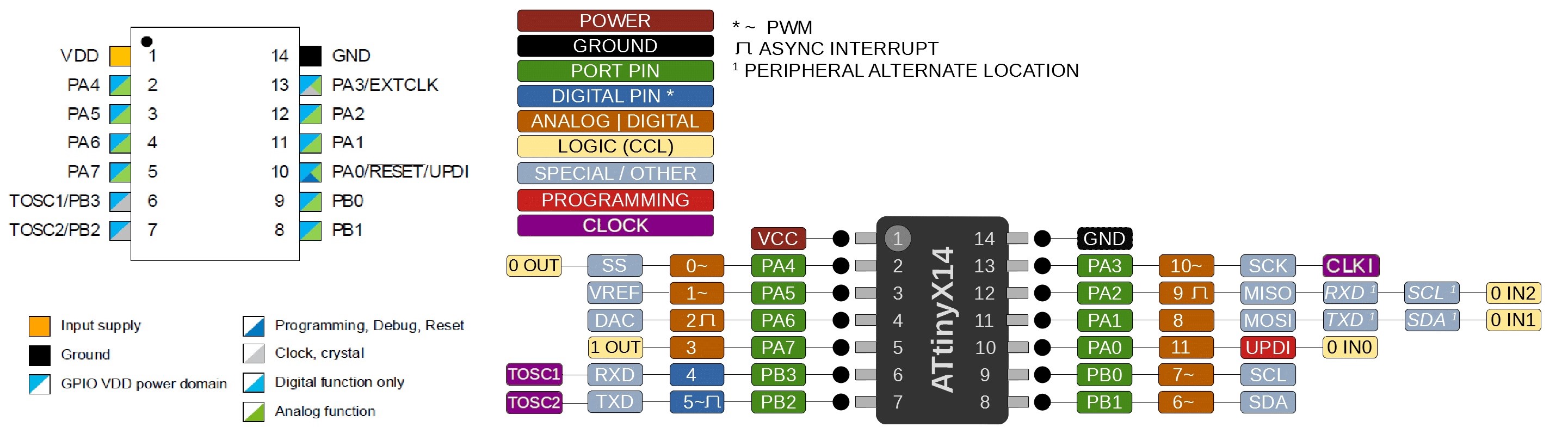
- VDD: Supply voltage.
- GND: Ground.
- Digital pins: Port A: PA0, PA1, PA2, PA3, PA4, PA5, PA6, PA7. Port B: PB0, PB1, PB2, PB3.
- Analog pins: PA1, PA2, PA3, PA4, PA5, PA6, PA7. Port B: PB0, PB1.
- UPDI Programming pin: PA0 (physical pin number 10).
- External Clock Pin: PA3.
All I/O pins can be configured with internal pullup resistance.
Within the communications section there are different types and their pins are different. It is clear that the different communication protocols cannot all be used at the same time, because they have pins in common.
- USART - Universal Synchronous and Asynchronous Receiver and Transmitter: It has the RX (PB2 or PA2) and the TX (PB3 or PA1).
- SPI - Serial Peripheral Interface: It has only MOSI (PA1), MISO (PA2), SCK (PA3), SS (PA4) .
- TWI - Two Wire Interface (I2C): It has SDA (PB1 or PA1) and SCL (PB0 or PA2).
Another important thing that the datasheet is telling us is that you have to keep in mind which kind of input component you are using, digital or analog: for instance, if you are using a temperature sensor (analog component) you have to connect it to an ACD (analog to digital converter) port otherwise the microcontroller isn't able to transform the information that is receiving from the sensor to a digital data.
ATtiny1624
As we have looked at the graph, there are more microcontrollers within the tinyAVR® 2 family. Another ATtiny I use is the 1624. I combine the Datasheet image with the one from the SpenceKonde website on the ATtiny1624.
- 14 pin package.
- Two internal clocks 16 and 20 MHz.
- 16 KB Flash Memory.
- 256 B EEPROM.
- 2 KB SRAM.
- Maximum voltage: 6V; minimum voltage -0.5 V.
- accurate analog features such as a 12-bit differential ADC with Programmable Gain Amplifier (PGA).
After looking at the basic features, you will find the pinning of the microcontroller.
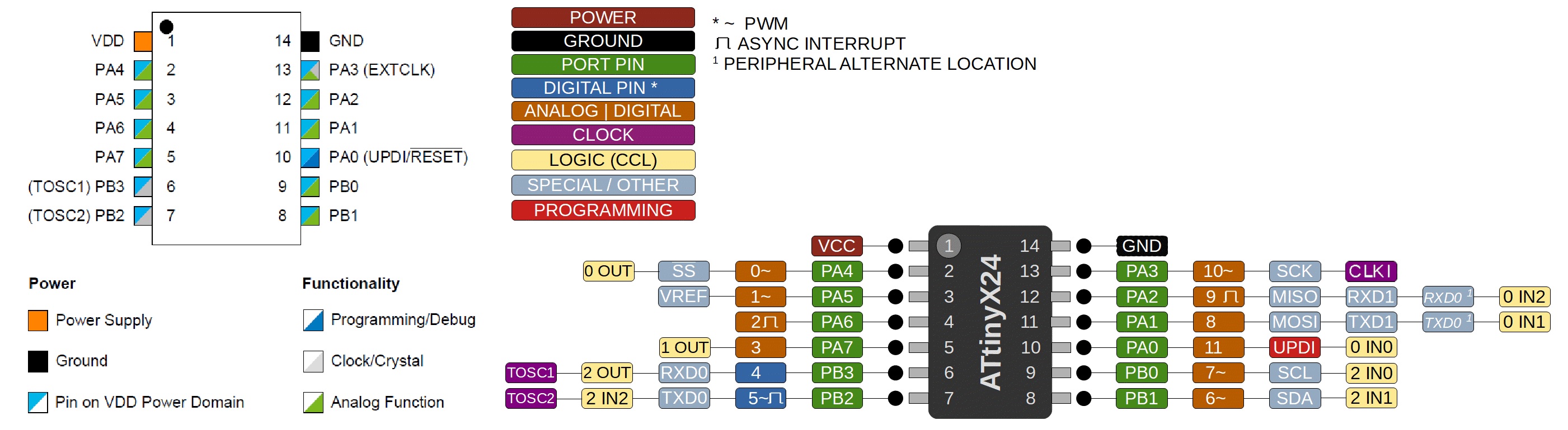
- VDD: Supply voltage.
- GND: Ground.
- Digital pins: Port A: PA0, PA1, PA2, PA3, PA4, PA5, PA6, PA7. Port B: PB0, PB1, PB2, PB3.
- Analog pins: PA1, PA2, PA3, PA4, PA5, PA6, PA7. Port B: PB0, PB1.
- UPDI Programming pin: PA0 (physical pin number 10).
- External Clock Pin: PA3.
All I/O pins can be configured with internal pullup resistance.
Within the communications section there are different types and their pins are different. It is clear that the different communication protocols cannot all be used at the same time, because they have pins in common.
- USART - Universal Synchronous and Asynchronous Receiver and Transmitter: It has the RX (PB2 or PA2) and the TX (PB3 or PA1).
- SPI - Serial Peripheral Interface: It has only MOSI (PA1), MISO (PA2), SCK (PA3), SS (PA4) .
- TWI - Two Wire Interface (I2C): It has SDA (PB1 or PA1) and SCL (PB0 or PA2).
Another important thing that the datasheet is telling us is that you have to keep in mind which kind of input component you are using, digital or analog: for instance, if you are using a temperature sensor (analog component) you have to connect it to an ACD (analog to digital converter) port otherwise the microcontroller isn't able to transform the information that is receiving from the sensor to a digital data. One Analog Comparator (AC) with scalable reference input: One 12-bit differential 375 ksps Analog-to-Digital Converter (ADC) with Programmable Gain Amplifier(PGA) and up to 15 input channels
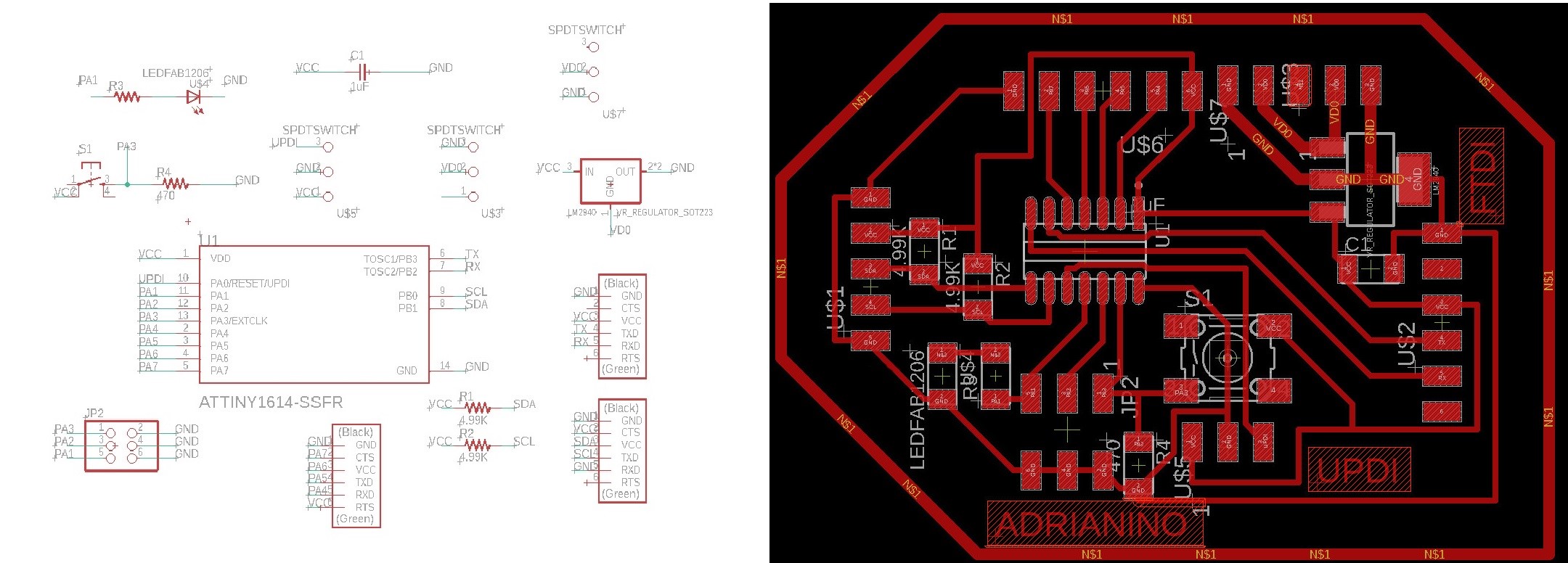
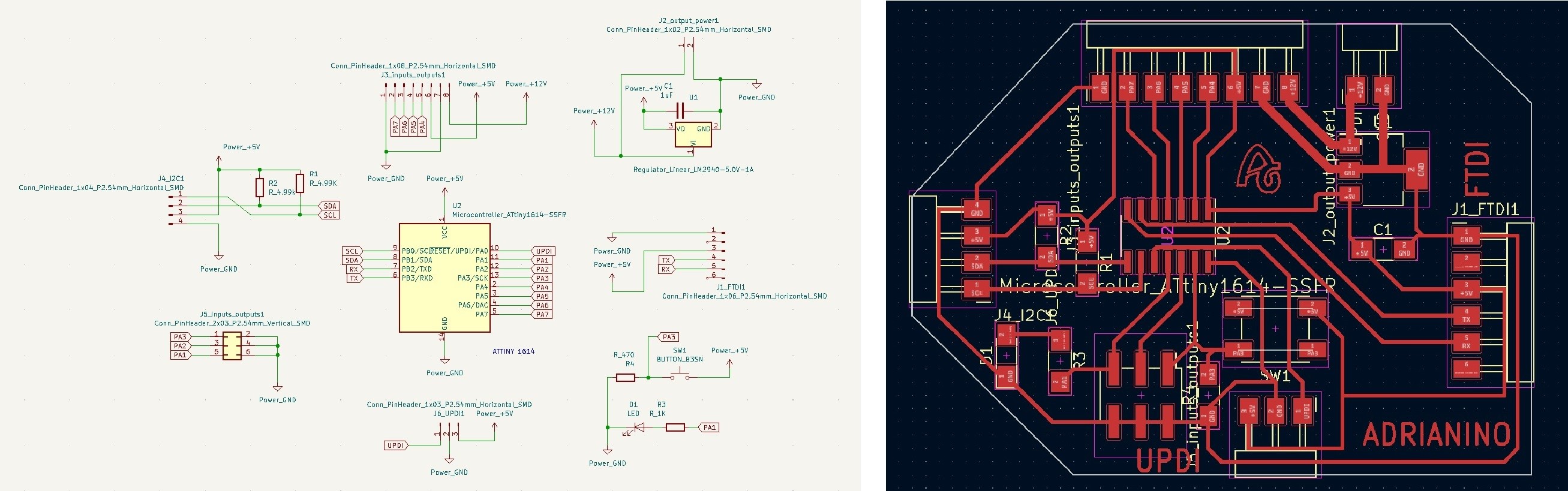
BOM and Schematic for Adrianino
This is the schematic where you can see all the components.
Adrianino |
Where to buy? | Amount | Price | Total price |
| Proto Board FR1 | Digikey | 1/4 board | 1,24 €/unit | 0,31 € |
| ATtiny1614 / ATtiny1624 | Digikey | 1 | 0,64 €/unit | 0,64 € |
| 1uF capacitor 50V | Digikey | 1 | 0,18 €/unit | 0,18 € |
| 4,99kΩ resistor | Digikey | 2 | 0,09 €/unit | 0,18 € |
| 499 Ω resistor | Digikey | 1 | 0,09 €/unit | 0,09 € |
| IC Regulator 5V 1A SOT223 | Digikey | 1 | 0,43 €/unit | 0,43 € |
| 1kΩ resistor | Digikey | 1 | 0,09 €/unit | 0,09 € |
| LED | Digikey | 1 | 0,35 €/unit | 0,35 € |
| Button | Digikey | 1 | 1,00 €/unit | 1,00 € |
| SMT RT Angle Male Header 0.1" (36pos) | Digikey | 9 | 0,15 €/unit | 1,35 € |
| Female 1 row horizontal header | Digikey | 14 | 0,15 €/unit | 2,10 € |
| Male 2 row vertical header | Digikey | 3 | 0,20 €/unit | 0,60 € |
| Total cost | 7,32 € |
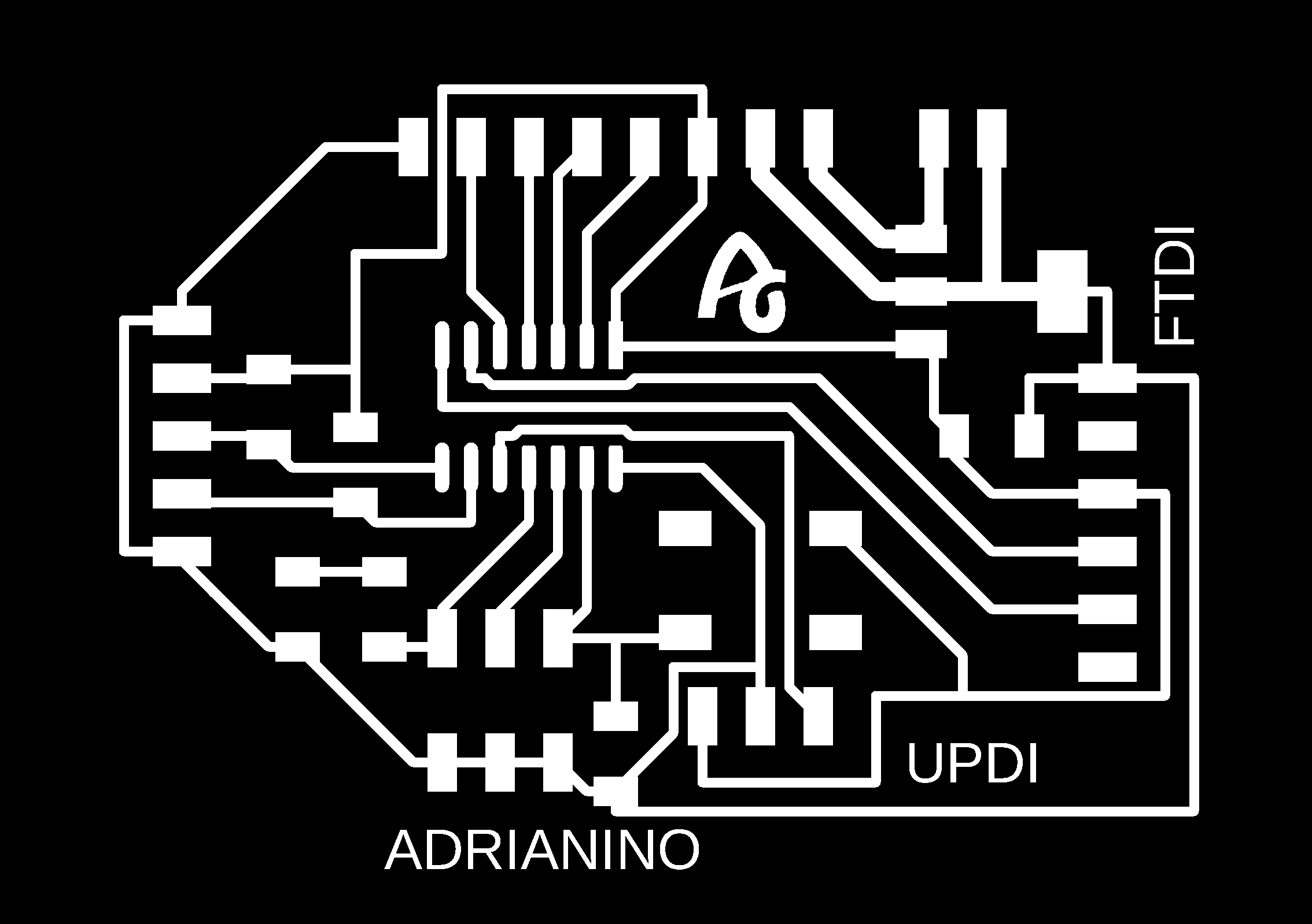
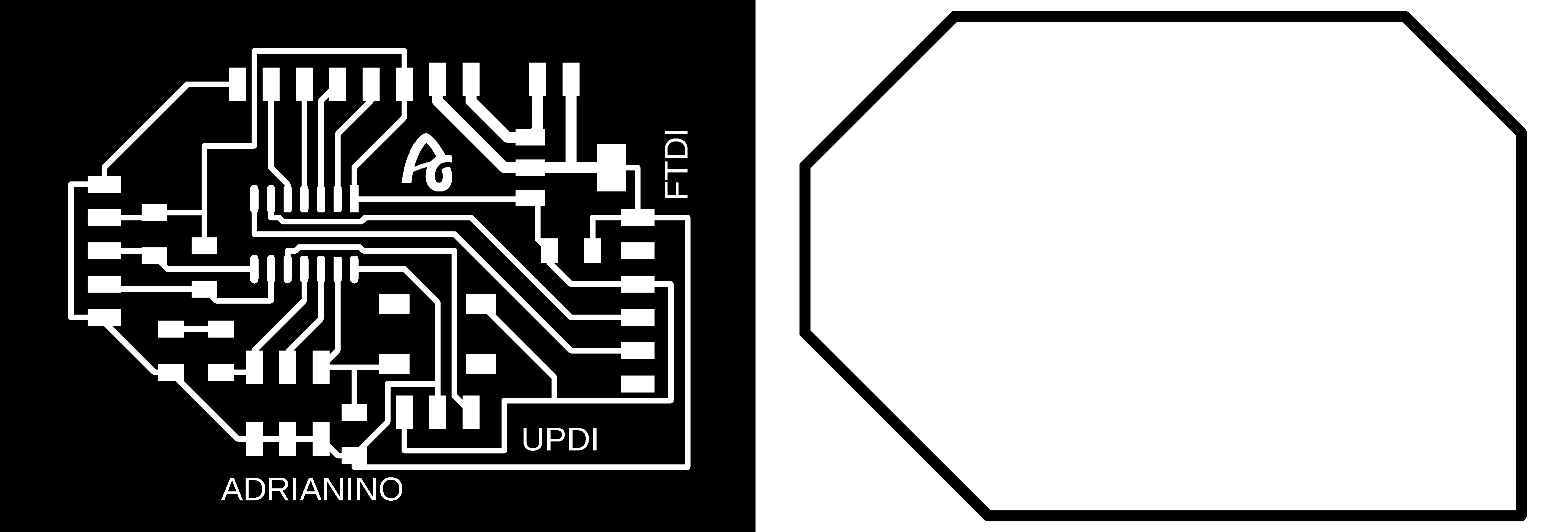
Board design
Here you can download the Eagle files and the PNG's. Here is a sample of the PNG's, traces and cutting lines.
Here you can download the KICAD 6 files and the SVG's. You can also see a 3D simulation of the board.
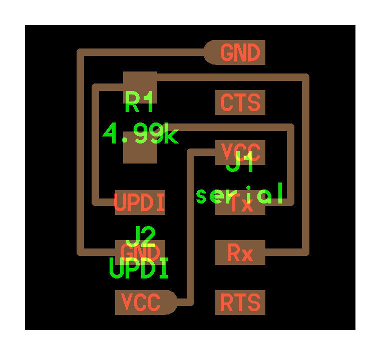
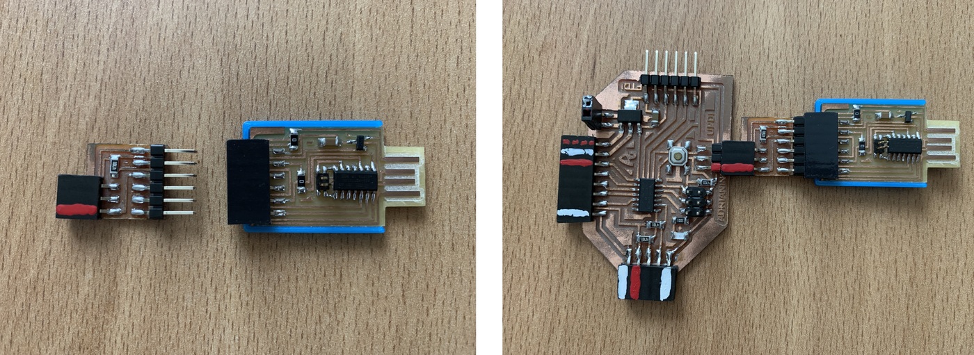
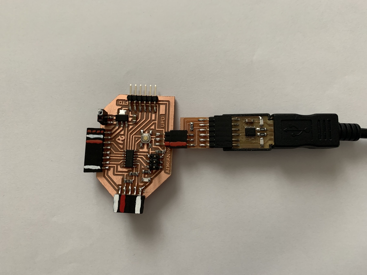
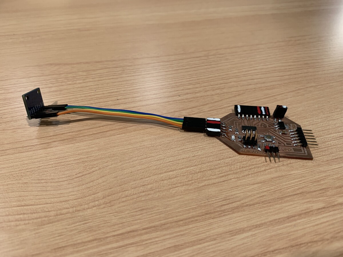
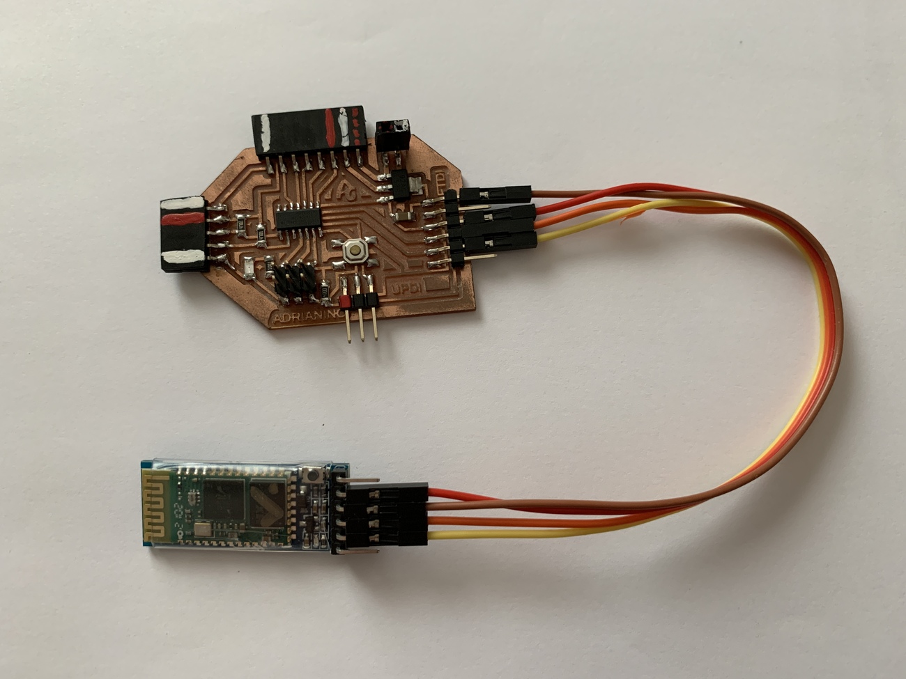
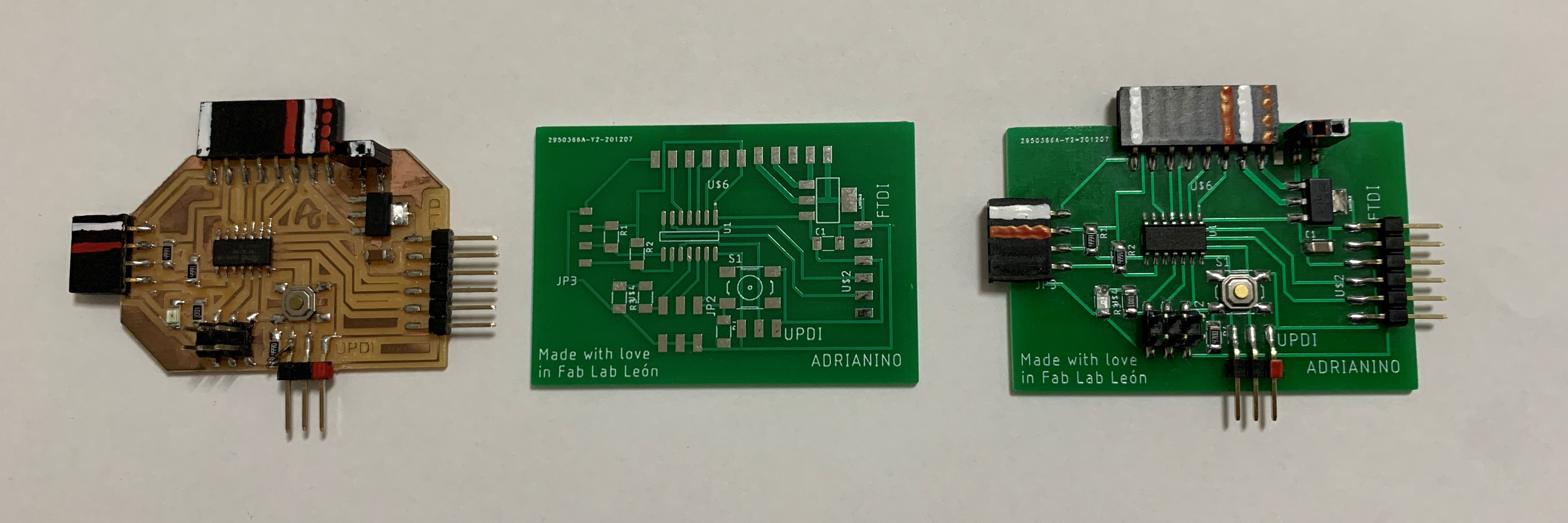
Serial UPDI + VCC module
During the January Instructors Bootcamp, I spoke with Neil and he thought it was a good idea to have a VCC pin added to this Serial to UPDI converter. The old version can be found at this link (the VCC pin is placed on the opposite side of Neil's design 😅).
You can find the files to create your Serial - UPDI + VCC converter here.
In this case I use hello.USB-serial.FT230X, a USB to FTDI converter with the FT230X chip. If you want to make one, you can follow the steps in the following link in my documentation, Electronics Production.

Now as a novelty, you can also use the SAMD11C Serial with the Serial + UPDI module to program the ATtiny 1 Series. If you want to make one, you can follow the following link in the documentation.
Operation
The connection is very simple, we only need the FTDI-USB and we connect the Serial UPDI + VCC module to the board, in this case to the Adrianino that has the three pins (UPDI + GND + VCC).
Programming
Windows + Arduino
At the beginning of January 2021, the programming method for the new AVR microcontrollers was updated. By updating megaTinyCore you can now upload directly from the Arduino IDE.
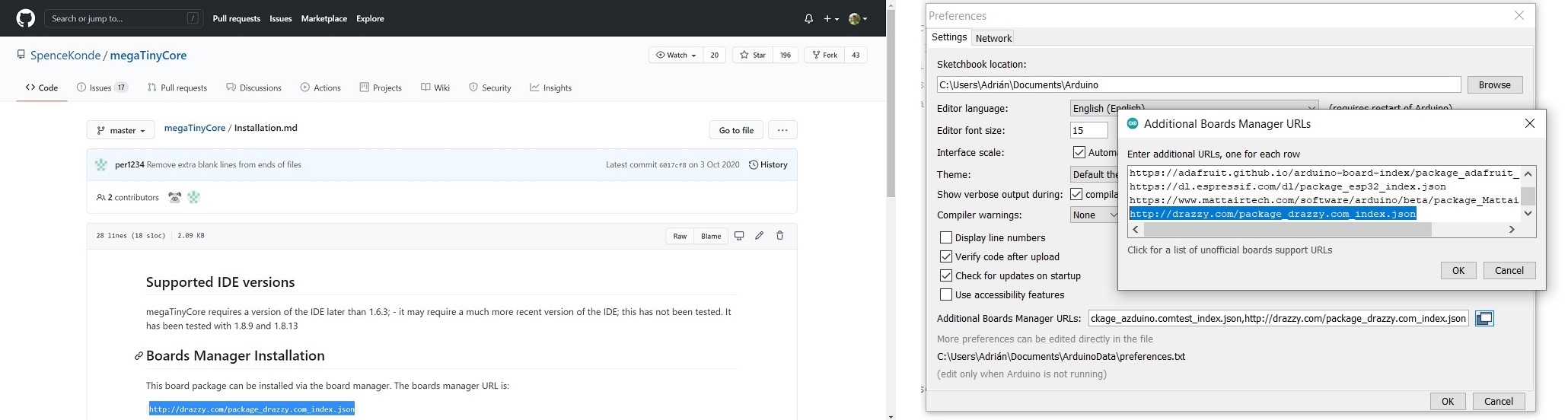
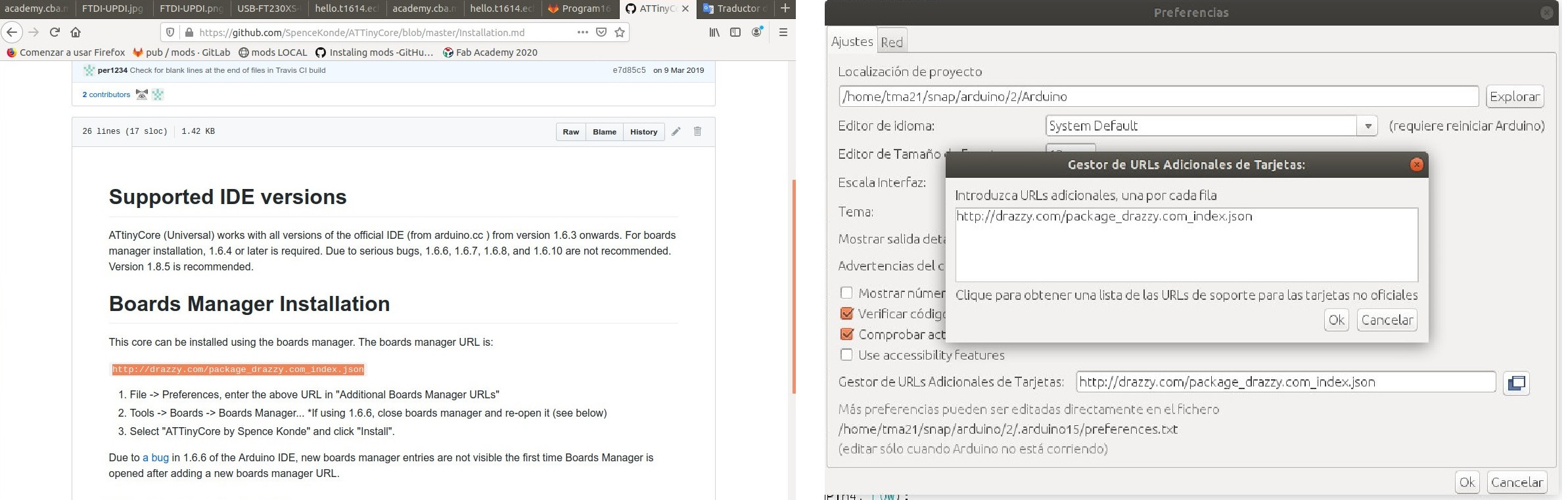
- 1. For this I install Arduino. Within Arduino, in the preferences tab we will add the URL to load the Arduino IDE with other cards or microcontrollers. Spence Konde tutorial.I mark the compilation tick. The boards manager URL is: http://drazzy.com/package_drazzy.com_index.json
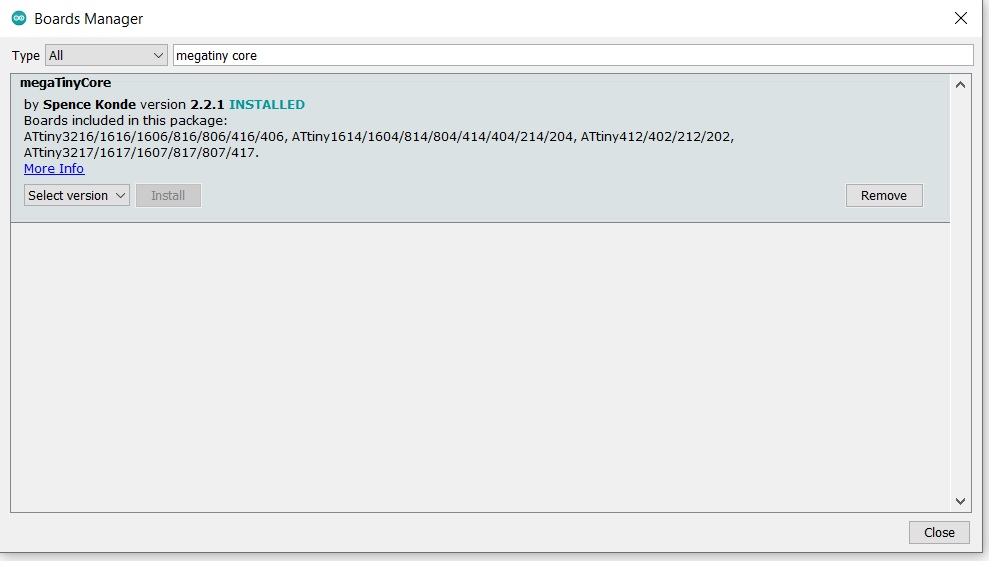
- 2. In tools, we will look for the boards and the boards manager. We will search for "megaTinyCore by Spence Konde" and install it.
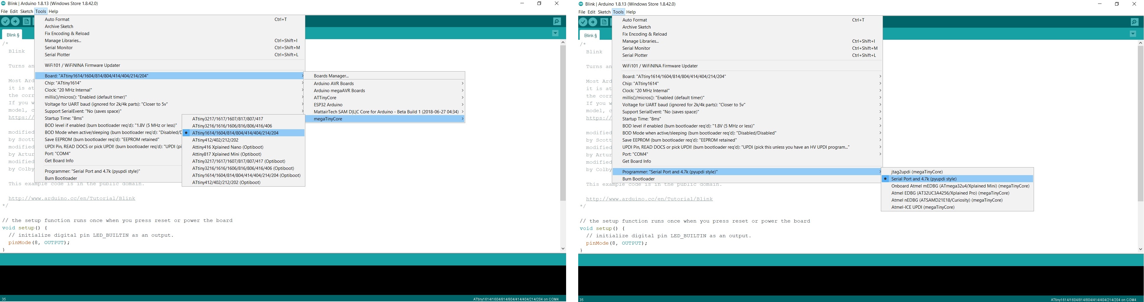
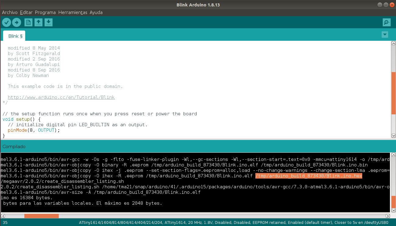
- 3. I configure the Arduino IDE for the ATtiny 1614/ ATtiny1624; I configure the clock to 20MHz and in my case the communication port with the COM4 microcontroller. It is important to have the FTDI-USB connected and choose the "Serial Port and 4.7k (pyupdi style) programmer.
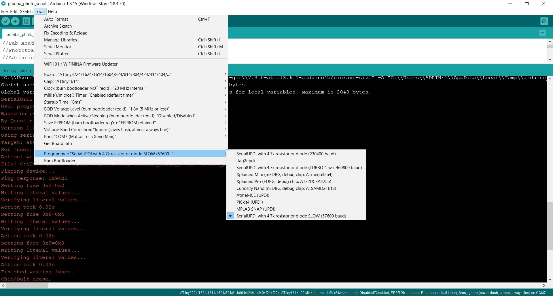
ATTENTION. With the latest version of megaTinyCore, if you have errors loading the program, I recommend that you use the selection "SerialUPDI with 4.7k resistor or diode SLOW (57600baud)"
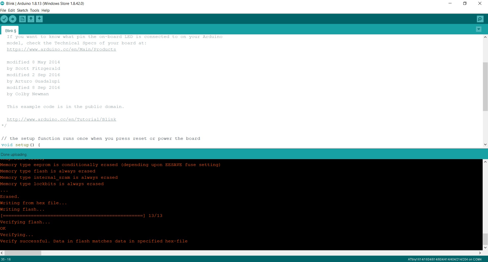
- 4. For this example I am going to use the Blink program, on pin PA1 (8 in Arduino) where the LED is integrated. 😍 We will press the upload button and the program will be loaded into the ATtiny. At the bottom of the Arduino IDE it will notify us of the upload of the program.
In this short video you can see the process of loading the programming and the operation of a Blink on pin PA1 (8 in Arduino) where the LED is integrated. 😍
Linux + Arduino + PyUPDI
I follow the tutorial that Pablo taught me that they used in the Bootcamp in India that Santi from Fab Lab BCN created.
- 1. For this I install Arduino. Within Arduino, in the preferences tab we will add the URL to load the Arduino IDE with other cards or microcontrollers. Spence Konde tutorial.The boards manager URL is: http://drazzy.com/package_drazzy.com_index.json
- 2. I download "pyupdi".
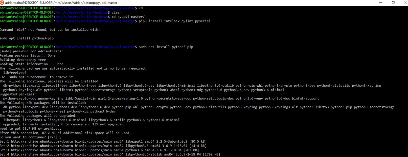
- 3. Open terminal. Install dependeces: pip3 install intelhex pylint pyserial
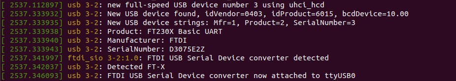
- 4. I connect the USB-FTDI.
- 5. I run dmesg -w
- 6. Connect and disconet the ftdi cable and take note of the "port name" where:
- 7. I configure the Arduino IDE for the ATtiny 1614; I configure the clock to 20MHz, the TX and RX ports and in my case the communication port with the /dev/ttyUSB0 microcontroller.

- 8. Only the code is compiled. In the Arduino IDE dialog box, we will see where the temporary files are located.
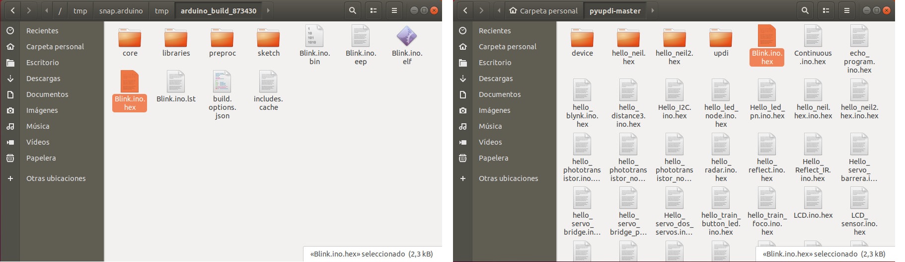
- 9. We look for the .hex file which is the one we need, it is in a temporary folder. Once located, we copy it and paste it in the pyupdi folder.
- 10. I connect it as follows. USB-Serial-FT230X + UPDI-VCC.
- 11. Go into the "pyupdi" folder.
- 12. Program the board using python -> run sudo python3 pyupdi.py -d tiny1614 -c /dev/ttyUSB0 -b 115200 -f Blink.ino.hex -v
In this short video you can see the process of loading the programming and the operation of a Blink on pin PA1 (8 in Arduino) where the LED is integrated. 😍
Video tutorial programing in Linux -> Bootcamp 2021
Video tutorial programing in Windows -> Bootcamp 2021
Inputs
Button
The button is the simplest element of the inputs. It is an open or closed contact that when we press it changes its state to closed or open.
In this case, the button is integrated on the board, on the PA3 pin (Arduino pin 10) and the LED on the PA1 pin (Arduino pin 8).
Here you will find the programming to use the button. Here you can find the Arduinio file to download. Below you can see a video of how it works.
//Fab Academy 2020 - Fab Lab León
//Button + LED
//Adrianino
//ATtiny1614 - ATtiny1624
//
//Original code:Neil Gershenfeld 12/8/19
// This work may be reproduced, modified, distributed,
// performed, and displayed for any purpose, but must
// acknowledge this project. Copyright is retained and
// must be preserved. The work is provided as is; no
// warranty is provided, and users accept all liability.
//


const int ledPin1 = 8;//first light
const int buttonPin = 10;// button pin
int buttonState = 0;//initial state of the button
int i = 0; //variable intensity led

void setup() { //declaration of inputs and outputs
  pinMode(ledPin1, OUTPUT);
  pinMode(buttonPin, INPUT);
}
void loop() {
  buttonState = digitalRead(buttonPin);// we read the state of the button
  if (buttonState == HIGH) { //if we press the button
  digitalWrite(ledPin1, HIGH);
  delay(500);
  digitalWrite(ledPin1, LOW);
  delay(500);
  digitalWrite(ledPin1, HIGH);
  delay(500);
  digitalWrite(ledPin1, LOW);
  delay(500);
  digitalWrite(ledPin1, HIGH);
  delay(2000);
  digitalWrite(ledPin1, LOW);
  delay(1000);

}
  else {  //if we don't press the button
  digitalWrite(ledPin1, LOW);
  }
}
Pyroelectric
A passive infrared sensor (or PIR sensor) is an electronic sensor that measures infrared (IR) light radiated from objects in its field of view. They are mainly used in PIR-based motion detectors.
In this case we only need three cables; one for VCC, another for GND and another for the sensor output that in our case we will connect it to pin PA4 (0 in Arduino).
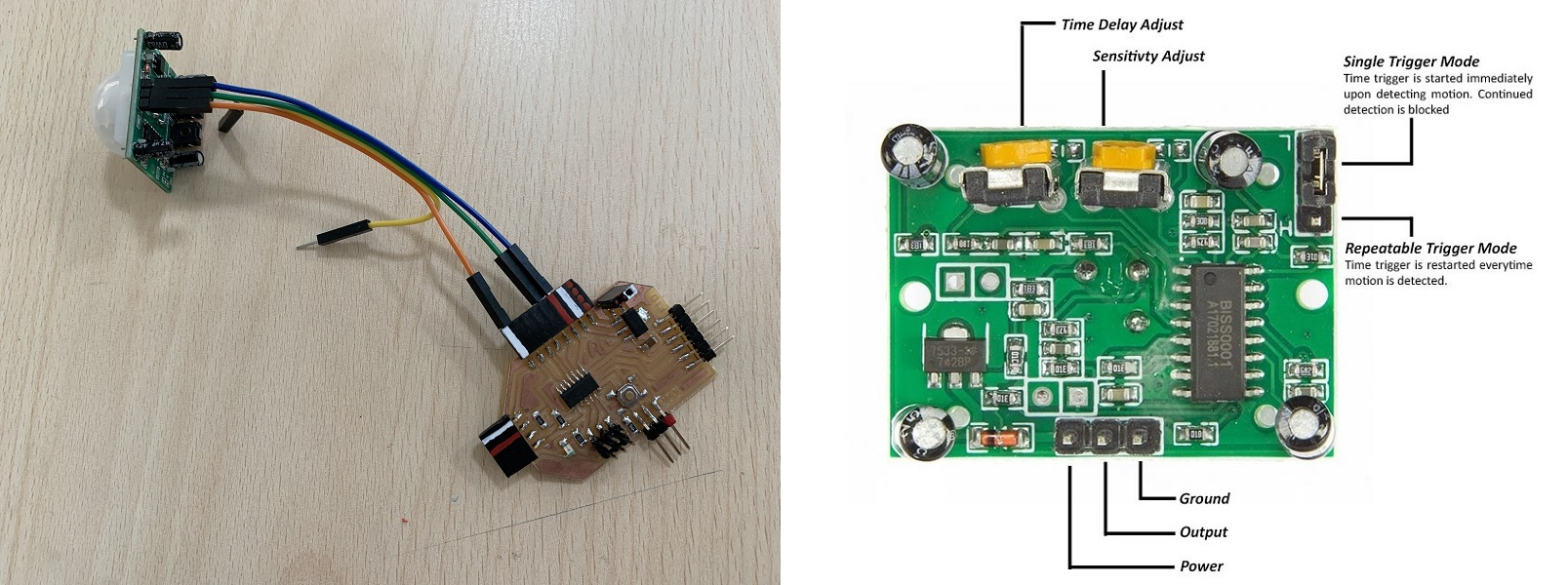
Here you will find the programming to use a digital sensor such as the PIR. Here you can find the Arduino and Processing files to download. Below you can see a video of how it works.
//Fab Academy 2020 - Fab Lab León
//PIR sensor
//Adrianino
//ATtiny1614 - ATtiny1624


const int RadarPin = 0; // digital input pin to hook the sensor to
int value = 6; // variable to store the value coming from the sensor
void setup()
{
  Serial.begin(115200); // initialize serial communications
  pinMode(RadarPin, INPUT); //digital input pin
}

void loop()
{
  int value= digitalRead(RadarPin); // read the value from the sensor (0 or 1)
  Serial.println(value);  // print value to Serial Monitor
}
Doppler radar
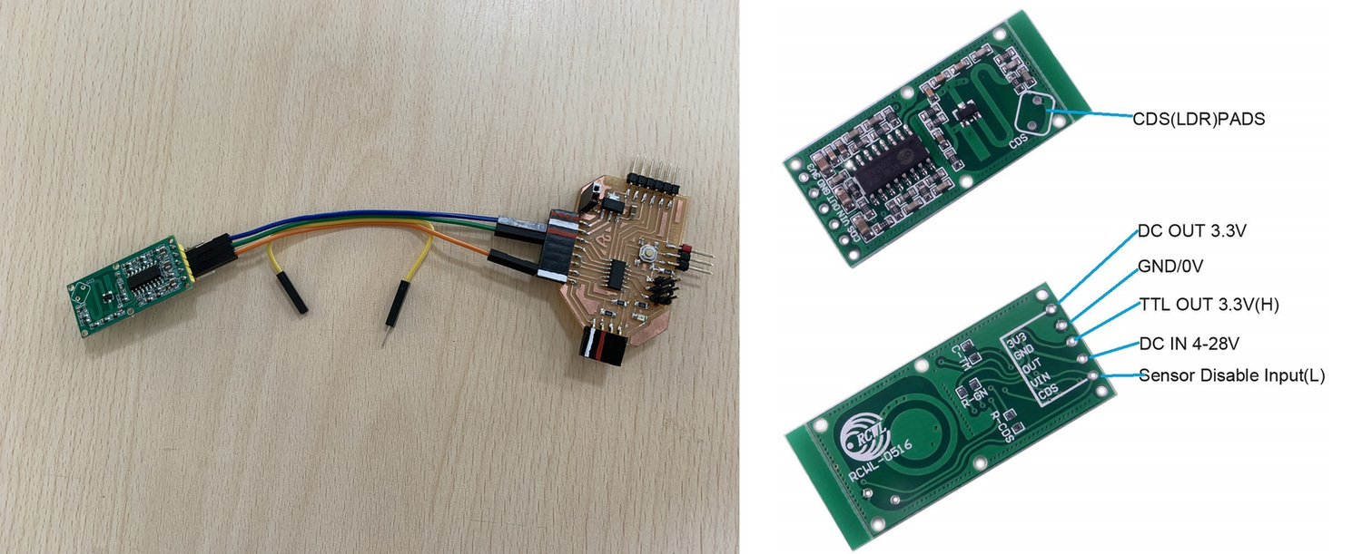
The RCWL-0516 is a Dopler Microwave Radar Sensor.It is an alternative to traditional PIR infrared motion detectors. Faced with these, it has certain differences, which will be an advantage or disadvantage depending on the needs of our project.
First of all, PIR sensors require the moving object to have a temperature difference from the environment. For this reason, they are able to detect people, but not moving objects. In contrast, the RCWL-0516 detects any object that is moving, regardless of its temperature. On the other hand, PIR sensors have sensitivity problems when the ambient temperature is high. The RCWL-0516, on the other hand, does not have this problem and works correctly between -20ºC to 80ºC. In terms of detection range, the RCWL-0516 has a greater range than PIR sensors, being able to easily reach 5-7 meters of range.
Finally, the RCWL-0516 is omnidirectional, that is, it detects movement in 360º. This is a difference from PIR sensors, which have a certain "angle of view". There are even versions of PIR with a narrow beam, for example to control windows or doors.
In this case we only need three cables; one for VCC, another for GND and another for the sensor output that in our case we will connect it to pin PA4 (0 in Arduino).
Here you will find the programming to use a digital sensor such as the PIR. Here you can find the Arduino and Processing files to download. Below you can see a video of how it works.
//Fab Academy 2020 - Fab Lab León
//Doppler radar
//Adrianino
//ATtiny1614  - ATtiny1624


const int RadarPin = 0; // digital input pin to hook the sensor to
int value = 6; // variable to store the value coming from the sensor
void setup()
{
  Serial.begin(115200); // initialize serial communications
  pinMode(RadarPin, INPUT); //digital input pin
}

void loop()
{
  int value= digitalRead(RadarPin); // read the value from the sensor (0 or 1)
  Serial.println(value);  // print value to Serial Monitor
}
Ultrasonic sensor
The HC-SR04 ultrasonic sensor uses sonar to determine distance to an object like bats do. It offers excellent non-contact range detection with high accuracy and stable readings in an easy-to-use package. It comes complete with ultrasonic transmitter and receiver modules.
In this case we only need four cables; one for VCC, one for GND, another cable for the Trigger (PA4, Arduino pin 0) and another for the Echo (PA5, Arduino pin 1).
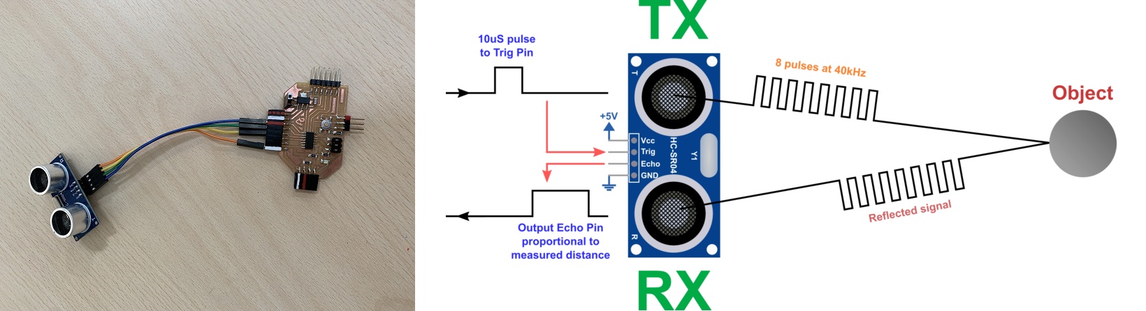
Here you will find the programming to use a digital sensor such as the Ultrasonic sensor. Here you can find the Arduino and Processing files to download. Below you can see a video of how it works.
- Arduino Hello Ultrasonic sensor
- Processing Hello Ultrasonic sensor
//Fab Academy 2020 - Fab Lab León
//Ultrasonic sensor
//Adrianino
//ATtiny1614  - ATtiny1624


const int EchoPin = 1;
const int TriggerPin = 0;

void setup() {
   Serial.begin(115200);
   pinMode(TriggerPin, OUTPUT);
   pinMode(EchoPin, INPUT);
}

void loop() {
   int cm = ping(TriggerPin, EchoPin);
  Serial.print("");
   Serial.println(cm);
   delay(1000);
}

int ping(int TriggerPin, int EchoPin) {
   long duration, distanceCm;

   digitalWrite(TriggerPin, LOW);  //to generate a clean pulse we set LOW 4us
   delayMicroseconds(4);
   digitalWrite(TriggerPin, HIGH);  //we generate Trigger (trigger) of 10us
   delayMicroseconds(10);
   digitalWrite(TriggerPin, LOW);

   duration = pulseIn(EchoPin, HIGH);  //we measure the time between pulses, in microseconds

   distanceCm = duration * 10 / 292/ 2;   //we convert distance, in cm
   return distanceCm;
}
Time of flight VL53L0X
I use a module that integrates the VL53L0X sensor. The module is sold by Adafruit, although in my case I bought it from Amazon. In this case of the pinout that the sensor brings, I will only use the VCC, GND, SDA and SCL pins. This information is obtained from the Luis Llamas website.
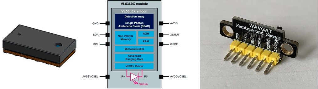
In this case we only need four cables; one for VCC, one for GND, another cable for the SDA (PB1, Arduino pin 6) and another for the SCL (PB0, Arduino pin 7).
Here you will find the programming to use the Time of Flight sensor. Here you can find the Arduino and Processing files to download.Below you can see a video of how it works. Recommendation: Download the program from the link, in the text the symbols <> of the libraries are missing.
- Arduino Time of Flight sensor
- Processing Time of Flight sensor
//Fab Academy 2020 - Fab Lab León
//Time of Flight
//Adrianino
//ATtiny1614  - ATtiny1624

/* This example shows how to get single-shot range
 measurements from the VL53L0X. The sensor can optionally be
 configured with different ranging profiles, as described in
 the VL53L0X API user manual, to get better performance for
 a certain application. This code is based on the four
 "SingleRanging" examples in the VL53L0X API.

 The range readings are in units of mm. */

#include Wire.h
#include VL53L0X.h

VL53L0X sensor;


// Uncomment this line to use long range mode. This
// increases the sensitivity of the sensor and extends its
// potential range, but increases the likelihood of getting
// an inaccurate reading because of reflections from objects
// other than the intended target. It works best in dark
// conditions.

//#define LONG_RANGE


// Uncomment ONE of these two lines to get
// - higher speed at the cost of lower accuracy OR
// - higher accuracy at the cost of lower speed

//#define HIGH_SPEED
//#define HIGH_ACCURACY


void setup()
{
  Serial.begin(115200);
  Wire.begin();

  sensor.setTimeout(500);
  if (!sensor.init())
  {
    Serial.println("Failed to detect and initialize sensor!");
    while (1) {}
  }

#if defined LONG_RANGE
  // lower the return signal rate limit (default is 0.25 MCPS)
  sensor.setSignalRateLimit(0.1);
  // increase laser pulse periods (defaults are 14 and 10 PCLKs)
  sensor.setVcselPulsePeriod(VL53L0X::VcselPeriodPreRange, 18);
  sensor.setVcselPulsePeriod(VL53L0X::VcselPeriodFinalRange, 14);
#endif

#if defined HIGH_SPEED
  // reduce timing budget to 20 ms (default is about 33 ms)
  sensor.setMeasurementTimingBudget(20000);
#elif defined HIGH_ACCURACY
  // increase timing budget to 200 ms
  sensor.setMeasurementTimingBudget(200000);
#endif
}

void loop()
{
  Serial.print(sensor.readRangeSingleMillimeters());
  if (sensor.timeoutOccurred()) { Serial.print(" TIMEOUT"); }

  Serial.println();
}
Time of flight VL53L1X
I use a module that integrates the VL53L1X sensor. The module is sold by Polulu, although in my case I bought it from Amazon. In this case of the pinout that the sensor brings, I will only use the VCC, GND, SDA and SCL pins.
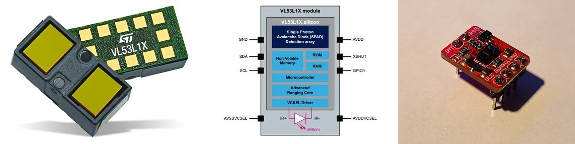
In this case we only need four cables; one for VCC, one for GND, another cable for the SDA (PB1, Arduino pin 6) and another for the SCL (PB0, Arduino pin 7).
Here you will find the programming to use the Time of Flight VL53L1X sensor. Here you can find the Arduino and Processing files to download. Below you can see a video of how it works. Recommendation: Download the program from the link, in the text the symbols <> of the libraries are missing.
- Arduino Time of Flight VL53L1X sensor
- Processing Time of Flight VL53L1X sensor
//Fab Academy 2021 - Fab Lab León
//Time of Flight VL53L1X
//Adrianino
//ATtiny1614  - ATtiny1624


/*
This example shows how to take simple range measurements with the VL53L1X. The
range readings are in units of mm.
*/

#include Wire.h
#include VL53L1X.h

VL53L1X sensor;

void setup()
{
  Serial.begin(115200);
  Wire.begin();
  Wire.setClock(400000); // use 400 kHz I2C

  sensor.setTimeout(500);
  if (!sensor.init())
  {
    Serial.println("Failed to detect and initialize sensor!");
    while (1);
  }

  // Use long distance mode and allow up to 50000 us (50 ms) for a measurement.
  // You can change these settings to adjust the performance of the sensor, but
  // the minimum timing budget is 20 ms for short distance mode and 33 ms for
  // medium and long distance modes. See the VL53L1X datasheet for more
  // information on range and timing limits.
  sensor.setDistanceMode(VL53L1X::Long);
  sensor.setMeasurementTimingBudget(50000);

  // Start continuous readings at a rate of one measurement every 50 ms (the
  // inter-measurement period). This period should be at least as long as the
  // timing budget.
  sensor.startContinuous(50);
}

void loop()
{
  Serial.print(sensor.read());
  if (sensor.timeoutOccurred()) { Serial.print(" TIMEOUT"); }

  Serial.println();
}
Hall effect
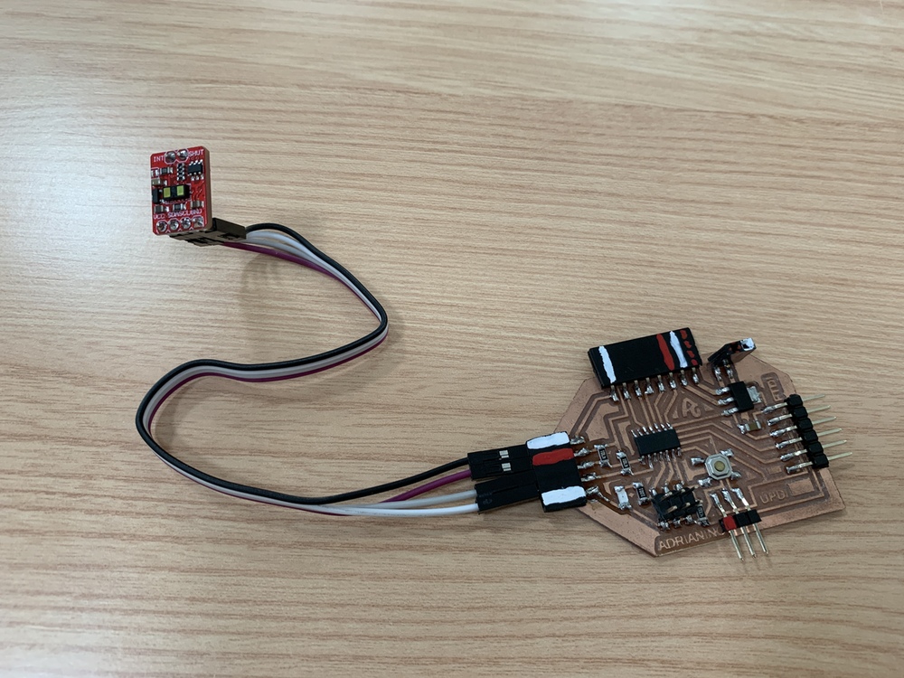
The Hall effect sensor or simply Hall sensor or Hall probe uses the Hall effect to measure magnetic fields or currents or to determine the position in which it is.
In this case, being a component without a module, I create my own. I design and manufacture a small board where I solder the hall effect sensor and with the flat connectors where there is no room for mistakes when connecting it. I use the analog input of the ATtiny1614 - ATtiny1624 PA4 (Arduino pin 0).
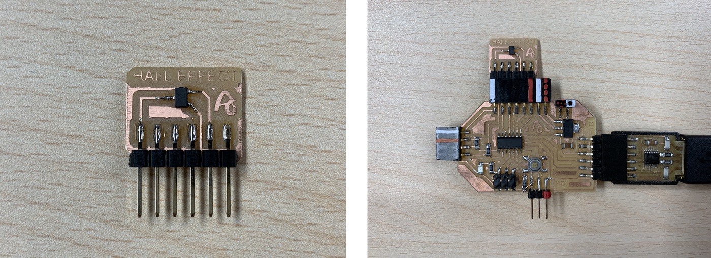
Here you can find the design in Eagle and the PNG's to create the board.
- Hall effect Schematic + Board
- Hall effect traces and interior

Here you will find the programming to use an analog sensor such as the Hall effect sensor. Here you can find the Arduino and Processing files to download. Below you can see a video of how it works.
- Arduino Hello Hall effect sensor
- Processing Hello Hall effect sensor
//Fab Academy 2020 - Fab Lab León
//Hall effect
//Adrianino
//ATtiny1614 - ATtiny1624
int sensorPin = 0; // analog input pin to hook the sensor to
int sensorValue = 0; // variable to store the value coming from the sensor
void setup() {
Serial.begin(115200); // initialize serial communications
}
void loop() {
sensorValue = analogRead(sensorPin); // read the value from the sensor
sensorValue = map(sensorValue, 0, 1024, 1024, 0);
Serial.println(sensorValue); // print value to Serial Monitor
//mySerial.println("x"); // print value "x" to Serial Monitor
delay(500); // short delay so we can actually see the numbers
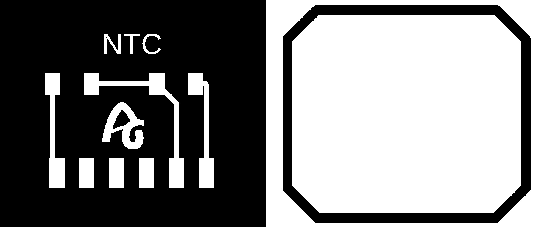
}Temperature. NTC.
The NTC sensor is a type of resistance whose value varies as a function of temperature in a more pronounced way than a common resistance. Its operation is based on the variation of the resistivity that a semiconductor presents with temperature.
In this case, being a component without a module, I create my own. I design and manufacture a small board where I solder the NTC sensor, a 10K resistor and with the flat connectors where there is no room for mistakes when connecting it. I use the analog input of the ATtiny1614 - ATtiny1624 PA4 (Arduino pin 0).
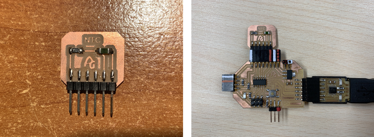
Here you can find the design in Eagle and the PNG's to create the board.
Here you will find the programming to use an analog sensor such as the NTC sensor. Here you can find the Arduino and Processing files to download. Below you can see a video of how it works.
- Arduino Hello NTC Temperature sensor
- Processing Hello NTC Temperature sensor
//Fab Academy 2020 - Fab Lab León
//NTC
//Adrianino
//ATtiny1614  - ATtiny1624
int sensorPin = 0;    // analog input pin to hook the sensor to
int sensorValue = 0;  // variable to store the value coming from the sensor

void setup() {
  Serial.begin(115200); // initialize serial communications
}

void loop() {
  sensorValue = analogRead(sensorPin); // read the value from the sensor
  sensorValue = map(sensorValue, 482, 890, 19, 180);
  Serial.println(sensorValue); // print value to Serial Monitor
  //mySerial.println("x"); // print value "x" to Serial Monitor
  delay(500); // short delay so we can actually see the numbers
}
Phototransistor. Visible.
The Phototransistor sensor is a three-layer semiconductor device which has a light-sensitive base region. The base senses the light and converts it into the current which flows between the collector and the emitter region.
In this case, being a component without a module, I create my own. I design and manufacture a small board where I solder the Phototransistor sensor, a 10K resistor and with the flat connectors where there is no room for mistakes when connecting it. I use the analog input of the ATtiny1614 - ATtiny1624 PA4 (Arduino pin 0).
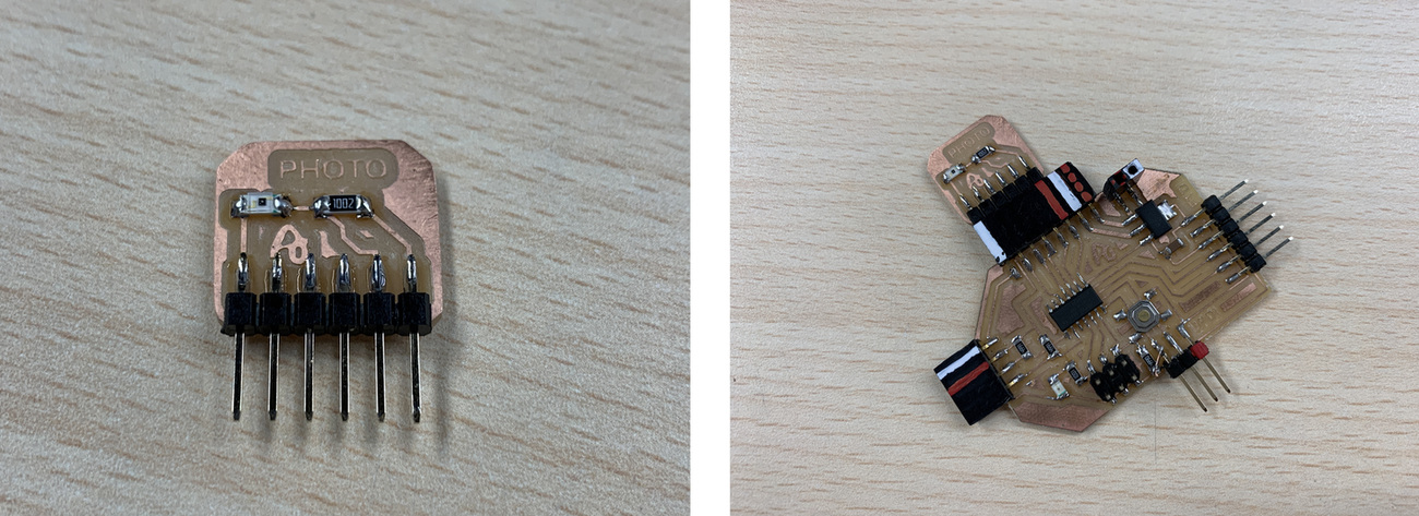
Here you can find the design in Eagle and the PNG's to create the board.
- Phototransistor Schematic + Board
- Phototransistor traces and interior
Here you will find the programming to use an analog sensor such as the Phototransistor sensor. Here you can find the Arduino and Processing files to download. Below you can see a video of how it works.
- Arduino Hello Phototransistor sensor
- Processing Hello Phototransistor sensor
//Fab Academy 2020 - Fab Lab León
//Phototransistor
//Adrianino
//ATtiny1614 - ATtiny1624
int sensorPin = 0;    // analog input pin to hook the sensor to
int sensorValue = 0;  // variable to store the value coming from the sensor

void setup() {
  Serial.begin(115200); // initialize serial communications
}

void loop() {
  sensorValue = analogRead(sensorPin); // read the value from the sensor
  sensorValue = map(sensorValue, 0, 1024, 1024, 0);
  Serial.println(sensorValue); // print value to Serial Monitor
  //mySerial.println("x"); // print value "x" to Serial Monitor
  delay(500); // short delay so we can actually see the numbers
}
Phototransistor. IR.
The Phototransistor IR sensor is a three-layer semiconductor device which has a light-sensitive base region. The base senses the IR and converts it into the current which flows between the collector and the emitter region.
In this case, being a component without a module, I create my own. I design and manufacture a small board where I solder the Phototransistor IR sensor, a 10K resistor, a IR LED, a 1K resistor and with the flat connectors where there is no room for mistakes when connecting it. I use the analog input of the ATtiny1614 - ATtiny1624 PA4 (Arduino pin 0).

Here you can find the design in Eagle and the PNG's to create the board.
- Phototransistor IR Schematic + Board
- Phototransistor IR traces and interior

Here you will find the programming to use an analog sensor such as the Phototransistor sensor. Here you can find the Arduino and Processing files to download. Below you can see a video of how it works.
- Arduino Hello Phototransistor IR sensor
- Processing Hello Phototransistor IR sensor
/******************************************************************************
QRD1114_Proximity_Example.ino
Example sketch for SparkFun's QRD1114 Reflectance Proximity Sensor
  (https://www.sparkfun.com/products/246)
Jim Lindblom @ SparkFun Electronics
May 2, 2016

Modified by Adrián Torres Omaña

Phototransistor IR
Adrianino
ATtiny1614 - ATtiny1624

******************************************************************************/
const int Sensor = 0; // Sensor output voltage

void setup()
{
  Serial.begin(115200);
  pinMode(Sensor, INPUT);
}

void loop()
{
  // Read in the ADC and convert it to a voltage:
  int proximityADC = analogRead(Sensor);
  float proximityV = (float)proximityADC * 5.0 / 1023.0;
  Serial.println(proximityV);
  delay(100);
}
Color.
I use a module that integrates the VEML6040 sensor, you can find it in the following Amazon link. It also incorporates an LED. To directly connect the module to the Adrianino, it is necessary to create a small board with a 3,3V regulator. In this case of the pinout that the sensor brings, I will only use the VCC, GND, SDA and SCL pins.
With the manufactured board, we will connect the sensor module on the left and on the right with the I2C connector.
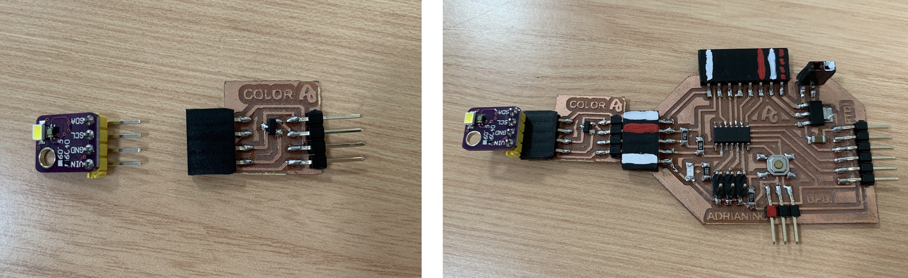
Here you can find the design in Eagle and the PNG's to create the board.

Here you will find the programming to use an color sensor. My friend Marta Verde helped me for the Processing program, thank you 😍. Here you can find the Arduino and Processing files to download. Below you can see a video of how it works. Recommendation: Download the program from the link, in the text the symbols <> of the libraries are missing.
- Processing Hello Color sensor
//Fab Academy 2021 - Fab Lab León
//Color
//Adrianino
//ATtiny1614 - ATtiny1624

/*

The MIT License (MIT)

Copyright (c) 2015 thewknd

Permission is hereby granted, free of charge, to any person obtaining a copy
of this software and associated documentation files (the "Software"), to deal
in the Software without restriction, including without limitation the rights
to use, copy, modify, merge, publish, distribute, sublicense, and/or sell
copies of the Software, and to permit persons to whom the Software is
furnished to do so, subject to the following conditions:

The above copyright notice and this permission notice shall be included in all
copies or substantial portions of the Software.

THE SOFTWARE IS PROVIDED "AS IS", WITHOUT WARRANTY OF ANY KIND, EXPRESS OR
IMPLIED, INCLUDING BUT NOT LIMITED TO THE WARRANTIES OF MERCHANTABILITY,
FITNESS FOR A PARTICULAR PURPOSE AND NONINFRINGEMENT. IN NO EVENT SHALL THE
AUTHORS OR COPYRIGHT HOLDERS BE LIABLE FOR ANY CLAIM, DAMAGES OR OTHER
LIABILITY, WHETHER IN AN ACTION OF CONTRACT, TORT OR OTHERWISE, ARISING FROM,
OUT OF OR IN CONNECTION WITH THE SOFTWARE OR THE USE OR OTHER DEALINGS IN THE
SOFTWARE.

*/

#include "Wire.h"
#include "veml6040.h"

VEML6040 RGBWSensor;
int r,g,b,w;

void setup() {
  Serial.begin(115200);
  Wire.begin();

  if(!RGBWSensor.begin()) {
    Serial.println("ERROR: couldn't detect the sensor");
    while(1){}
  }

  /*
   * init RGBW sensor with:
   *  - 320ms integration time
   *  - auto mode
   *  - color sensor enable
   */

	RGBWSensor.setConfiguration(VEML6040_IT_320MS + VEML6040_AF_AUTO + VEML6040_SD_ENABLE);

  delay(1500);
  Serial.println("Vishay VEML6040 RGBW color sensor auto mode example");
  Serial.println("CCT: Correlated color temperature in \260K");
  Serial.println("AL: Ambient light in lux");
  delay(1500);

}

void loop() {

  r = RGBWSensor.getRed();
  g = RGBWSensor.getGreen();
  b = RGBWSensor.getBlue();
  w = RGBWSensor.getWhite();


  Serial.print(r);
  Serial.print(",");
  Serial.print(g);
  Serial.print(",");
  Serial.print(b);
  Serial.print(",");
  Serial.println(w);
 }
3 axis accelerometer
I use a module that integrates the ADXL345 accelerometer, you can find it in the following Amazon link. In this case of the pinout that the sensor brings, I will only use the VCC, GND, SDA and SCL pins.
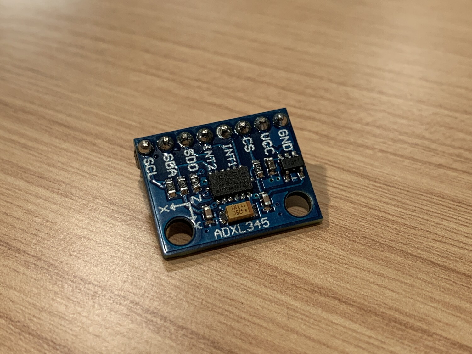
In this case we only need four cables; one for VCC, one for GND, another cable for the SDA (PB1, Arduino pin 6) and another for the SCL (PB0, Arduino pin 7).
Here you will find the programming to use 3 axis accelerometer. I have followed the following Adafruit tutorial where there is a section where it explains how to calibrate the accelerometer if necessary. My friend Marta Verde helped me for the Processing program, thank you 😍. Below you can see a video of how it works. Recommendation: Download the program from the link, in the text the symbols <> of the libraries are missing.
- Arduino 3 axis accelerometer
- Processing 3 axis accelerometer
//Fab Academy 2021 - Fab Lab León
//Accelerometer
//Adrianino
//ATtiny1614  - ATtiny1624

#include Wire.h
#include Adafruit_Sensor.h
#include Adafruit_ADXL345_U.h

/* Assign a unique ID to this sensor at the same time */
Adafruit_ADXL345_Unified accel = Adafruit_ADXL345_Unified(12345);

void displaySensorDetails(void)
{
  sensor_t sensor;
  accel.getSensor(&sensor);
  Serial.println("------------------------------------");
  Serial.print  ("Sensor:       "); Serial.println(sensor.name);
  Serial.print  ("Driver Ver:   "); Serial.println(sensor.version);
  Serial.print  ("Unique ID:    "); Serial.println(sensor.sensor_id);
  Serial.print  ("Max Value:    "); Serial.print(sensor.max_value); Serial.println(" m/s^2");
  Serial.print  ("Min Value:    "); Serial.print(sensor.min_value); Serial.println(" m/s^2");
  Serial.print  ("Resolution:   "); Serial.print(sensor.resolution); Serial.println(" m/s^2");
  Serial.println("------------------------------------");
  Serial.println("");
  delay(500);
}

void displayDataRate(void)
{
  Serial.print  ("Data Rate:    ");

  switch(accel.getDataRate())
  {
    case ADXL345_DATARATE_3200_HZ:
      Serial.print  ("3200 ");
      break;
    case ADXL345_DATARATE_1600_HZ:
      Serial.print  ("1600 ");
      break;
    case ADXL345_DATARATE_800_HZ:
      Serial.print  ("800 ");
      break;
    case ADXL345_DATARATE_400_HZ:
      Serial.print  ("400 ");
      break;
    case ADXL345_DATARATE_200_HZ:
      Serial.print  ("200 ");
      break;
    case ADXL345_DATARATE_100_HZ:
      Serial.print  ("100 ");
      break;
    case ADXL345_DATARATE_50_HZ:
      Serial.print  ("50 ");
      break;
    case ADXL345_DATARATE_25_HZ:
      Serial.print  ("25 ");
      break;
    case ADXL345_DATARATE_12_5_HZ:
      Serial.print  ("12.5 ");
      break;
    case ADXL345_DATARATE_6_25HZ:
      Serial.print  ("6.25 ");
      break;
    case ADXL345_DATARATE_3_13_HZ:
      Serial.print  ("3.13 ");
      break;
    case ADXL345_DATARATE_1_56_HZ:
      Serial.print  ("1.56 ");
      break;
    case ADXL345_DATARATE_0_78_HZ:
      Serial.print  ("0.78 ");
      break;
    case ADXL345_DATARATE_0_39_HZ:
      Serial.print  ("0.39 ");
      break;
    case ADXL345_DATARATE_0_20_HZ:
      Serial.print  ("0.20 ");
      break;
    case ADXL345_DATARATE_0_10_HZ:
      Serial.print  ("0.10 ");
      break;
    default:
      Serial.print  ("???? ");
      break;
  }
  Serial.println(" Hz");
}

void displayRange(void)
{
  Serial.print  ("Range:         +/- ");

  switch(accel.getRange())
  {
    case ADXL345_RANGE_16_G:
      Serial.print  ("16 ");
      break;
    case ADXL345_RANGE_8_G:
      Serial.print  ("8 ");
      break;
    case ADXL345_RANGE_4_G:
      Serial.print  ("4 ");
      break;
    case ADXL345_RANGE_2_G:
      Serial.print  ("2 ");
      break;
    default:
      Serial.print  ("?? ");
      break;
  }
  Serial.println(" g");
}

void setup(void)
{
#ifndef ESP8266
  while (!Serial); // for Leonardo/Micro/Zero
#endif
  Serial.begin(115200);
  Serial.println("Accelerometer Test"); Serial.println("");

  /* Initialise the sensor */
  if(!accel.begin())
  {
    /* There was a problem detecting the ADXL345 ... check your connections */
    Serial.println("Ooops, no ADXL345 detected ... Check your wiring!");
    while(1);
  }

  /* Set the range to whatever is appropriate for your project */
  accel.setRange(ADXL345_RANGE_16_G);
  // accel.setRange(ADXL345_RANGE_8_G);
  // accel.setRange(ADXL345_RANGE_4_G);
  // accel.setRange(ADXL345_RANGE_2_G);

  /* Display some basic information on this sensor */
  displaySensorDetails();

  /* Display additional settings (outside the scope of sensor_t) */
  displayDataRate();
  displayRange();
  Serial.println("");
}

void loop(void)
{
  /* Get a new sensor event */
  sensors_event_t event;
  accel.getEvent(&event);

  /* Display the results (acceleration is measured in m/s^2) */
  Serial.print(event.acceleration.x);
  Serial.print(",");
  Serial.print(event.acceleration.y);
  Serial.print(",");
  Serial.println(event.acceleration.z);

  //Serial.print("X: "); Serial.print(event.acceleration.x); Serial.print("  ");
  //Serial.print("Y: "); Serial.print(event.acceleration.y); Serial.print("  ");
  //Serial.print("Z: "); Serial.print(event.acceleration.z); Serial.print("  ");Serial.println("m/s^2 ");
  delay(500);
}
Step Response.
The step-response is a sensor that is made with two sheets of copper, separated from each other by a porous insulating material. It can be used to calculate the value of force, weight, resistance ... I have followed Robert Hart's tutorial as well as Neil's examples.
A series of pulses is sent through the TX electrode, which, depending on the material between the two electrodes, allows more or less that series of pulses to pass. In the following graph you can see how it works. The other electrode will be connected between two resistors, one for pull-up and the other for pull-down and to an analog input.
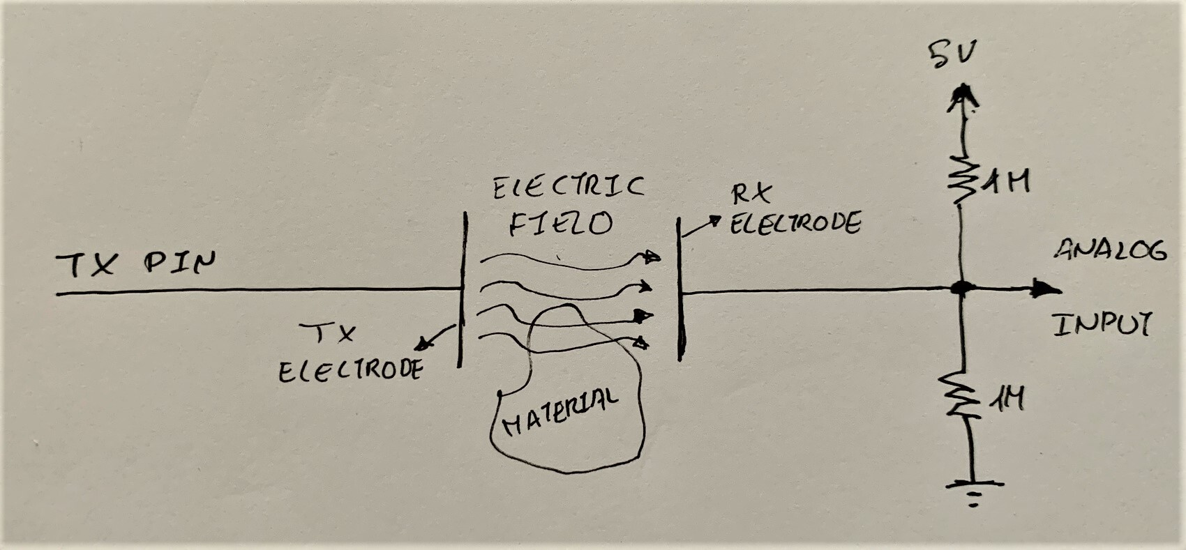
In this case, being a component without a module, I create my own. I design and manufacture a small board where I solder two 1M resistors and with flat connectors where there is no room for errors when connecting it. I use the analog input from the ATtiny1614 - ATtiny1624 PA5 (Arduino pin 1) for the RX and a digital output from the ATtiny1614 - ATtiny1624 PA6 (Arduino pin 2). Then with a connector there are two cables that connect the two electrodes (3M™ Copper Foil Tape).
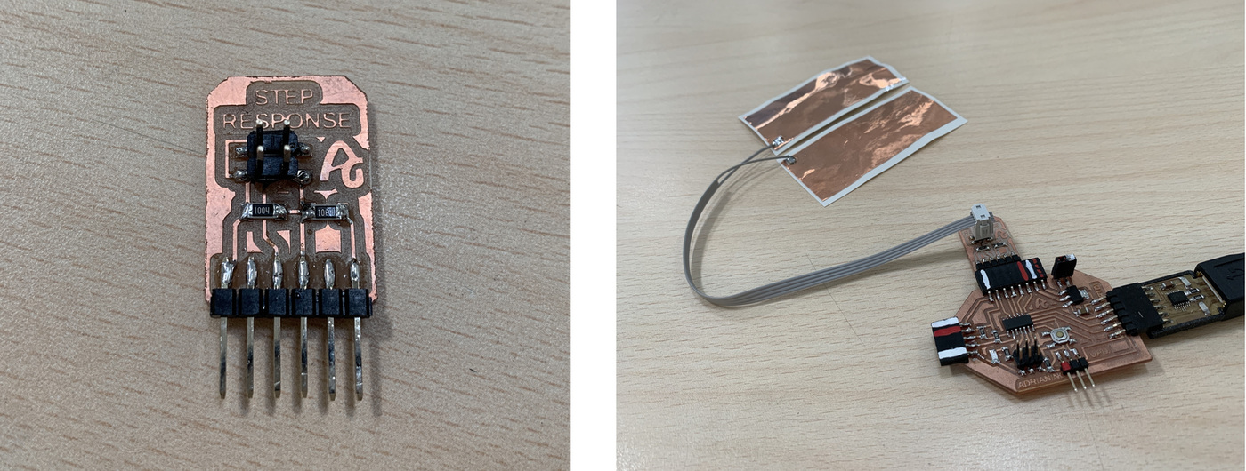
Here you can find the design in Eagle and the PNG's to create the board.
- Step Response Schematic + Board
- Step Response traces and interior

Here you will find the programming to use a Step Response sensor. Here you can find the Arduino and Processing files to download. Below you can see a video of how it works.
- Processing Step Response TX/RX
//tx_rx03  Robert Hart Mar 2019.
//https://roberthart56.github.io/SCFAB/SC_lab/Sensors/tx_rx_sensors/index.html

//Modified by Adrián Torres Omaña
//Fab Academy 2021
//Step Response TX, RX
//Adrianino
//ATtiny1614  - ATtiny1624

//  Program to use transmit-receive across space between two conductors.
//  One conductor attached to digital pin, another to analog pin.
//
//  This program has a function "tx_rx() which returns the value in a long integer.
//
//  Optionally, two resistors (1 MOhm or greater) can be placed between 5V and GND, with
//  the signal connected between them so that the steady-state voltage is 2.5 Volts.
//
//  Signal varies with electric field coupling between conductors, and can
//  be used to measure many things related to position, overlap, and intervening material
//  between the two conductors.
//


long result;   //variable for the result of the tx_rx measurement.
int analog_pin = 1; //  PA5 of the ATtiny1614
int tx_pin = 2;  //     PA6 of the ATtiny1614
void setup() {
pinMode(tx_pin,OUTPUT);      //Pin 2 provides the voltage step
Serial.begin(115200);
}


long tx_rx(){         //Function to execute rx_tx algorithm and return a value
                      //that depends on coupling of two electrodes.
                      //Value returned is a long integer.
  int read_high;
  int read_low;
  int diff;
  long int sum;
  int N_samples = 100;    //Number of samples to take.  Larger number slows it down, but reduces scatter.

  sum = 0;

  for (int i = 0; i < N_samples; i++){
   digitalWrite(tx_pin,HIGH);              //Step the voltage high on conductor 1.
   read_high = analogRead(analog_pin);        //Measure response of conductor 2.
   delayMicroseconds(100);            //Delay to reach steady state.
   digitalWrite(tx_pin,LOW);               //Step the voltage to zero on conductor 1.
   read_low = analogRead(analog_pin);         //Measure response of conductor 2.
   diff = read_high - read_low;       //desired answer is the difference between high and low.
 sum += diff;                       //Sums up N_samples of these measurements.
 }
  return sum;
}                         //End of tx_rx function.


void loop() {

result = tx_rx();
result = map(result, 8000, 11000, 0, 1024);  //I recommend mapping the values of the two copper plates, it will depend on their size
Serial.println(result);
delay(100);
}
This first video you can see how the two electrodes work with several sheets as intermediate material.
In this second video you can see how it works with a sponge as an intermediate material.
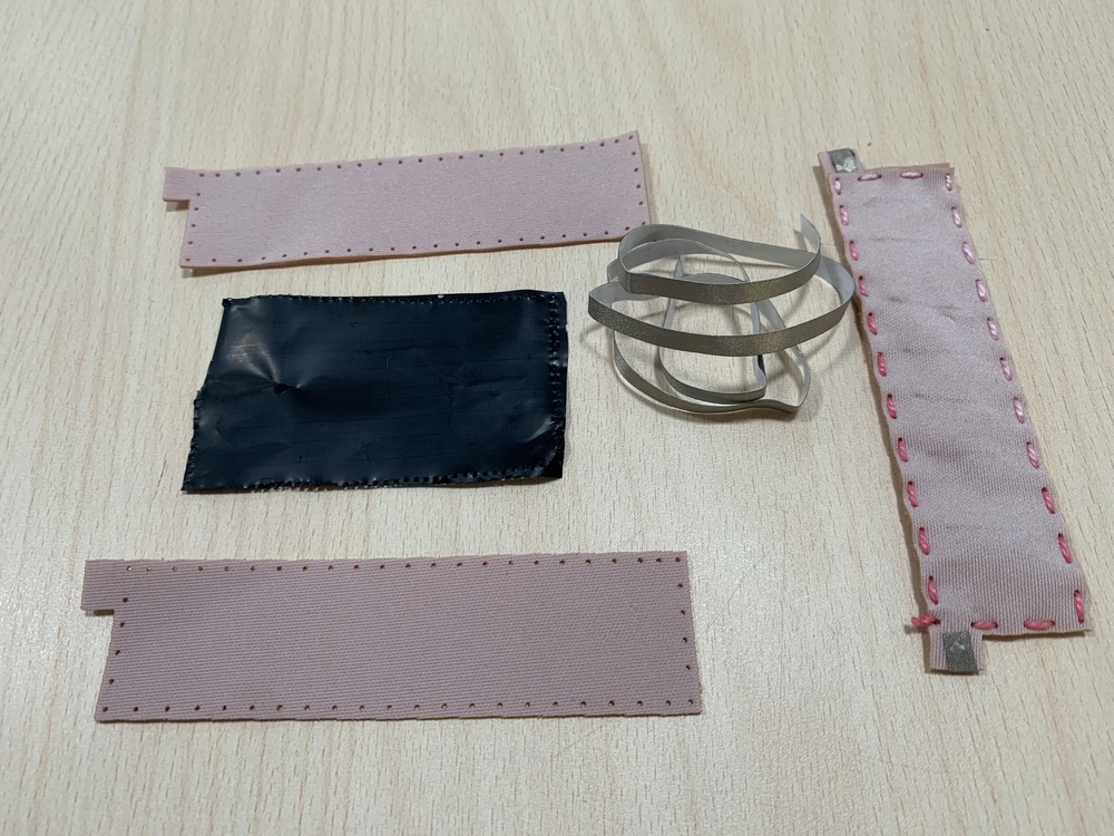
Textile Flexure Sensor.
In recent years, the field of e-textiles has experienced significant growth. E-textiles or electronic textiles, also known as smart fabrics, are fabrics in which electrical and electronic elements such as microcontrollers, sensors and actuators have been integrated that allow clothing to react, send information or interact with the environment. In some cases they are complemented with textile materials with certain conductive or electrical properties.
Thanks to the Fabricademy, in the E-Textiles class taught by Liza Stark and the knowledge of my instructor Nuria Robles I have created the sensor that I am going to connect to the Adrianino.
To manufacture this sensor, we will need fabric, conductive tape or conductive wire and velostat.
- Velostat: Is a Carbon impregnated black polyethylene film material of about 4 thousand thick and Volume resistivity is <500 Ohms/cm. Conductivity is not affected by humidity or aging. Here you can find the datsheet.
- Conductive tape: This Conductive Nylon tape goes great with our other interesting materials, such as copper tape, ITO glass or plastic, conductive inks, etc. We found that the metallic nylon fabric has some great improvements over plain copper tape. You can find more information here or buy it at this link.
To create the textile flex sensor we can cut the fabric with the laser cutter, and help us when it comes to sewing. I leave you the following diagram of how the sensor will work and the layers that it is composed of. Scheme made by Nuria Robles. 🥰
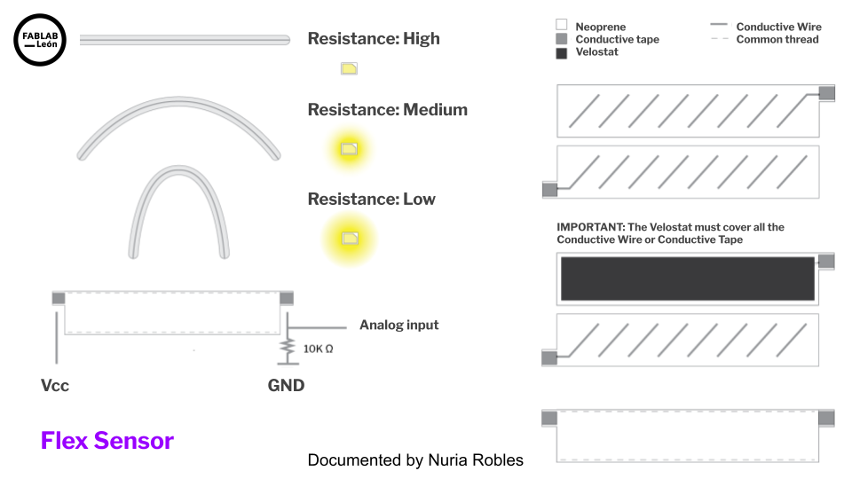
We will have this, two pieces of neoprene in this case, the velostat and the conductive tape. I will create inside a zig-zag pattern of conductive tape or conductive wire. Once I have the three parts, as if it were a "sandwich" one all putting the velostat in the middle.
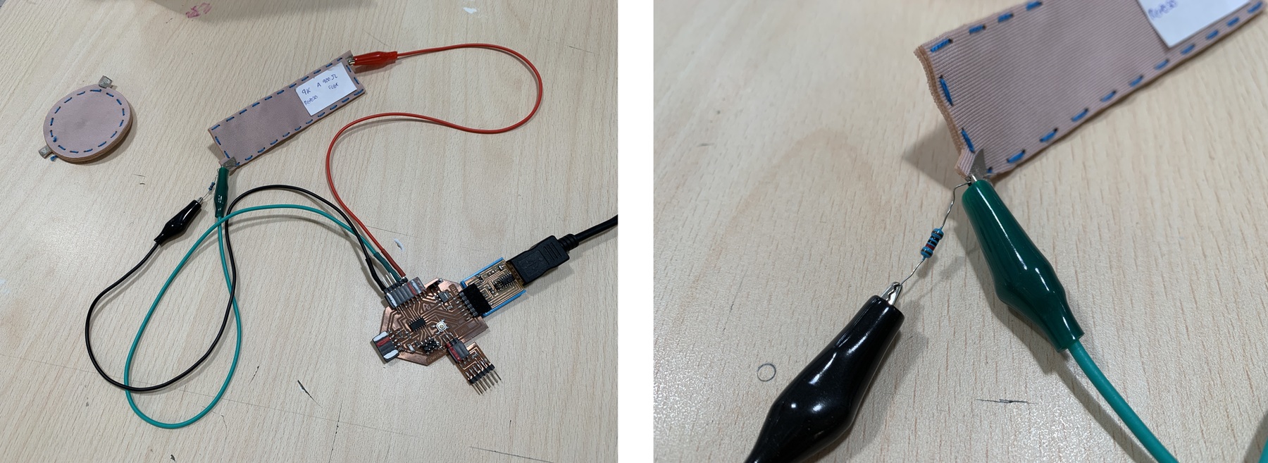
In this case I am going to use three crocodile clips connected to some male pins. In this case by color the red wire will go to VCC, the black to GND and the green one that is signal to PA4 (arduino pin 0). IMPORTANT: We also need to connect a 10k pull-down resistor at the sensor signal output.
Here you will find the programming to use a Textile Flexure Sensor. Here you can find the Arduino and Processing files to download. Below you can see a video of how it works.
- Arduino Textile Flexure Sensor
- Processing Textile Flexure Sensor
//Fab Academy 2021 - Fab Lab León
//Textile Flexure Sensor
//Adrianino
//ATtiny1614 - ATtiny1624
int sensorPin = 0;    // analog input pin to hook the sensor to
int sensorValue = 0;  // variable to store the value coming from the sensor

void setup() {
  Serial.begin(115200); // initialize serial communications
}

void loop() {
  sensorValue = analogRead(sensorPin); // read the value from the sensor
  sensorValue = map(sensorValue, 0, 1024, 0, 1024);
  Serial.println(sensorValue); // print value to Serial Monitor
  //mySerial.println("x"); // print value "x" to Serial Monitor
  delay(500); // short delay so we can actually see the numbers
}
Outputs
RGB LED
The RGB LED stands for Red, Blue and Green LEDs. RGB LED products combine these three colors to produce more than 16 million shades of light.
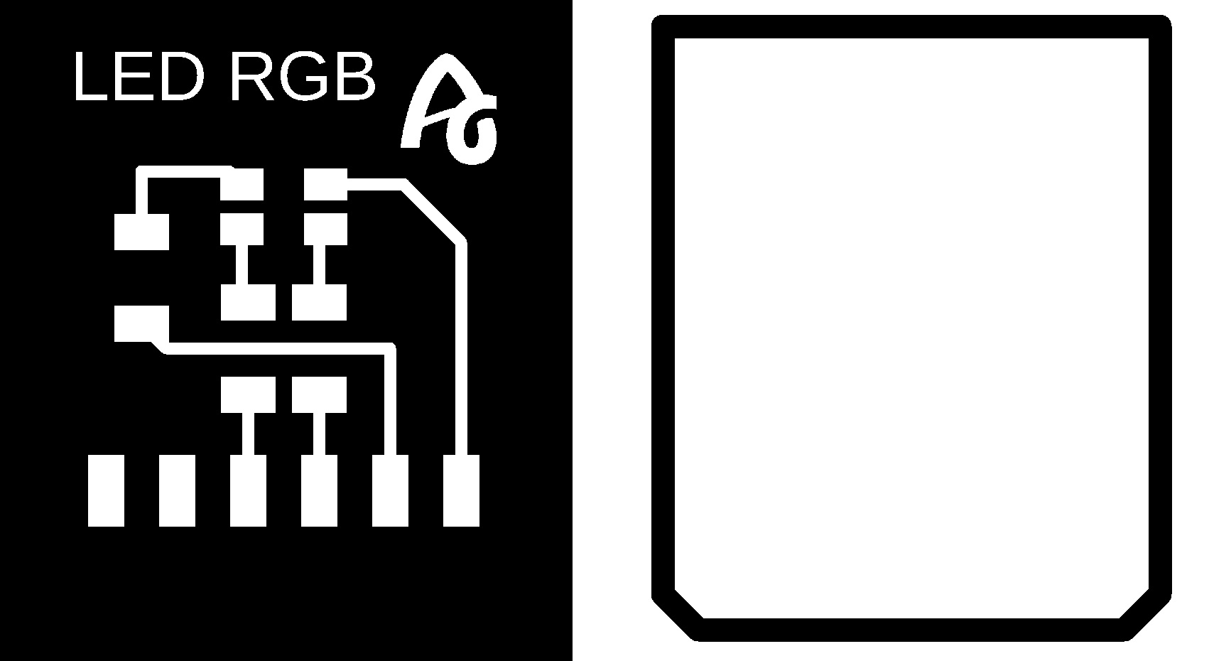
In this case, being a component without a module, I create my own. I design and manufacture a small board where I solder the RGB LED, two 1K resistors (for red and green color), a 499 resistor (for blue color) and with the flat connectors where there is no room for mistakes when connecting it. I use the digitals ouputs of the ATtiny1614 PA4 (Arduino pin 0), PA5 (Arduino pin 1), PA6 (Arduino pin 2).
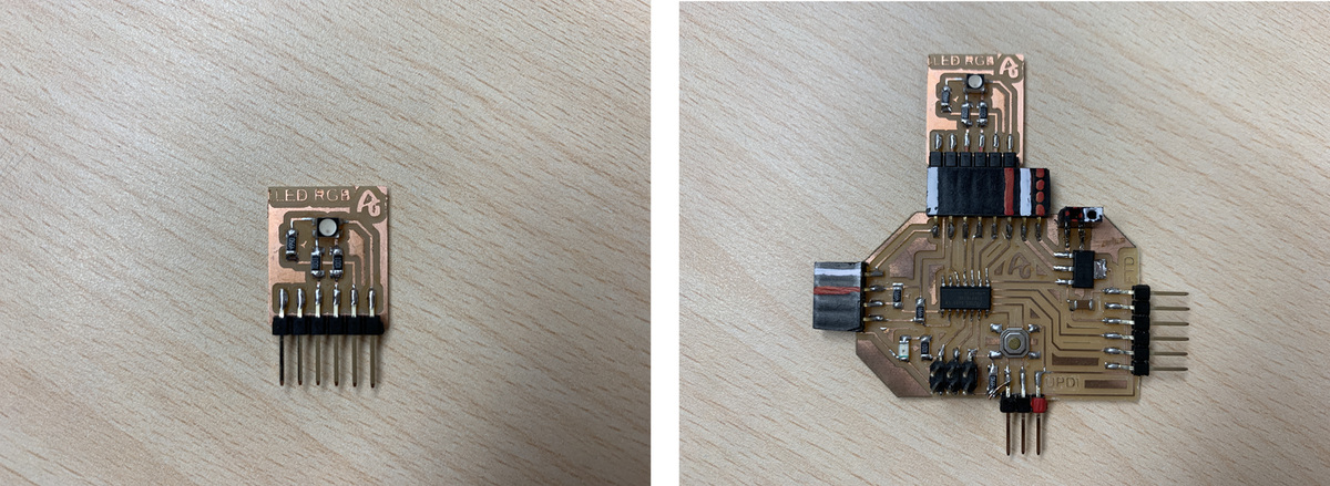
Here you can find the design in Eagle and the PNG's to create the board.
Here you will find the programming to use a RGB LED. Here you can find the Arduino file to download. Below you can see a video of how it works.
//Fab Academy 2020 - Fab Lab León
//RGB LED
//Adrianino
//ATtiny1614 - ATtiny1624
const byte COLOR_BLACK = 0b000;
const byte COLOR_BLUE = 0b100;
const byte COLOR_RED = 0b010;
const byte COLOR_GREEN = 0b001;
const byte COLOR_MAGENTA = 0b101;
const byte COLOR_CYAN = 0b011;
const byte COLOR_YELLOW = 0b110;
const byte COLOR_WHITE = 0b111;
const byte PIN_LED_R = 0;
const byte PIN_LED_G = 2;
const byte PIN_LED_B = 1;
void setup() {
pinMode(PIN_LED_R, OUTPUT);
pinMode(PIN_LED_G, OUTPUT);
pinMode(PIN_LED_B, OUTPUT);
displayColor(COLOR_BLACK);
}
void loop() {
displayColor(COLOR_RED);
delay(1000);
displayColor(COLOR_GREEN);
delay(1000);
displayColor(COLOR_BLUE);
delay(1000);
displayColor(COLOR_MAGENTA);
delay(1000);
displayColor(COLOR_CYAN);
delay(1000);
displayColor(COLOR_YELLOW);
delay(1000);
displayColor(COLOR_WHITE);
delay(1000);
displayColor(COLOR_BLACK);
delay(1000);
}
void displayColor(byte color) {
digitalWrite(PIN_LED_R, !bitRead(color, 0));
digitalWrite(PIN_LED_G, !bitRead(color, 2));
digitalWrite(PIN_LED_B, !bitRead(color, 1));
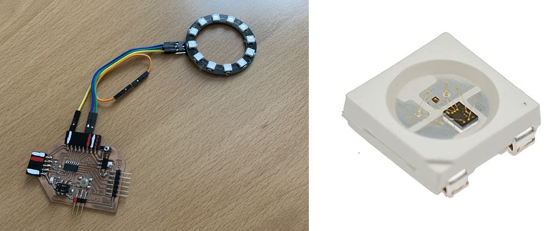
}NeoPixel Ring
After looking at RGB LEDs, a quicker and easier solution is NeoPixels. NeoPixels are individually addressable RGB LEDs, that is, LEDs that have an integrated logic circuit within themselves, a circuit that makes it possible to control the color of each LED in a sequence of chained LEDs with a single digital pin.
The format that the NeoPixels can be found can be loose, strip or ring. In my case I am going to use a 12 NeoPixel ring like this one from Adafruit or this one from Amazon, which use the NeoPixel WS2812 model.
In this case we only need three cables; one for VCC, another for GND and another for the signal output DI that in our case we will connect it to pin PA4 (0 in Arduino). The circuit can be powered by a 9V battery.
Here you will find the programming to use a NeoPixel Ring. Here you can find the Arduino file to download. Below you can see a video of how it works. Recommendation: Download the program from the link, in the text the symbols <> of the libraries are missing.
//Fab Academy 2021 - Fab Lab León
//NeoPixel
//Adrianino
//ATtiny1614 - ATtiny1624
#include
#define PIN 0
// Parameter 1 = number of pixels in strip
// Parameter 2 = Arduino pin number (most are valid)
// Parameter 3 = pixel type
// NEO_GRB Pixels are wired for GRB bitstream (most NeoPixel products)
// NEO_RGB Pixels are wired for RGB bitstream (v1 FLORA pixels, not v2)
// NEO_RGBW Pixels are wired for RGBW bitstream (NeoPixel RGBW products)
tinyNeoPixel strip = tinyNeoPixel(12, PIN, NEO_GRB + NEO_KHZ800);
// IMPORTANT: To reduce NeoPixel burnout risk, add 1000 uF capacitor across
// pixel power leads, add 300 - 500 Ohm resistor on first pixel's data input
// and minimize distance between Arduino and first pixel. Avoid connecting
// on a live circuit...if you must, connect GND first.
void setup() {
strip.begin();
strip.show(); // Initialize all pixels to 'off'
}
void loop() {
// Some example procedures showing how to display to the pixels:
colorWipe(strip.Color(255, 0, 0), 50); // Red
colorWipe(strip.Color(0, 255, 0), 50); // Green
colorWipe(strip.Color(0, 0, 255), 50); // Blue
//colorWipe(strip.Color(0, 0, 0, 255), 50); // White RGBW
// Send a theater pixel chase in...
theaterChase(strip.Color(127, 127, 127), 50); // White
theaterChase(strip.Color(127, 0, 0), 50); // Red
theaterChase(strip.Color(0, 0, 127), 50); // Blue
rainbow(20);
rainbowCycle(20);
theaterChaseRainbow(50);
}
// Fill the dots one after the other with a color
void colorWipe(uint32_t c, uint8_t wait) {
for (uint16_t i = 0; i < strip.numPixels(); i++) {
strip.setPixelColor(i, c);
strip.show();
delay(wait);
}
}
void rainbow(uint8_t wait) {
uint16_t i, j;
for (j = 0; j < 256; j++) {
for (i = 0; i < strip.numPixels(); i++) {
strip.setPixelColor(i, Wheel((i + j) & 255));
}
strip.show();
delay(wait);
}
}
// Slightly different, this makes the rainbow equally distributed throughout
void rainbowCycle(uint8_t wait) {
uint16_t i, j;
for (j = 0; j < 256 * 5; j++) { // 5 cycles of all colors on wheel
for (i = 0; i < strip.numPixels(); i++) {
strip.setPixelColor(i, Wheel(((i * 256 / strip.numPixels()) + j) & 255));
}
strip.show();
delay(wait);
}
}
//Theatre-style crawling lights.
void theaterChase(uint32_t c, uint8_t wait) {
for (int j = 0; j < 10; j++) { //do 10 cycles of chasing
for (int q = 0; q < 3; q++) {
for (uint16_t i = 0; i < strip.numPixels(); i = i + 3) {
strip.setPixelColor(i + q, c); //turn every third pixel on
}
strip.show();
delay(wait);
for (uint16_t i = 0; i < strip.numPixels(); i = i + 3) {
strip.setPixelColor(i + q, 0); //turn every third pixel off
}
}
}
}
//Theatre-style crawling lights with rainbow effect
void theaterChaseRainbow(uint8_t wait) {
for (int j = 0; j < 256; j++) { // cycle all 256 colors in the wheel
for (int q = 0; q < 3; q++) {
for (uint16_t i = 0; i < strip.numPixels(); i = i + 3) {
strip.setPixelColor(i + q, Wheel((i + j) % 255)); //turn every third pixel on
}
strip.show();
delay(wait);
for (uint16_t i = 0; i < strip.numPixels(); i = i + 3) {
strip.setPixelColor(i + q, 0); //turn every third pixel off
}
}
}
}
// Input a value 0 to 255 to get a color value.
// The colours are a transition r - g - b - back to r.
uint32_t Wheel(byte WheelPos) {
WheelPos = 255 - WheelPos;
if (WheelPos < 85) {
return strip.Color(255 - WheelPos * 3, 0, WheelPos * 3);
}
if (WheelPos < 170) {
WheelPos -= 85;
return strip.Color(0, WheelPos * 3, 255 - WheelPos * 3);
}
WheelPos -= 170;
return strip.Color(WheelPos * 3, 255 - WheelPos * 3, 0);
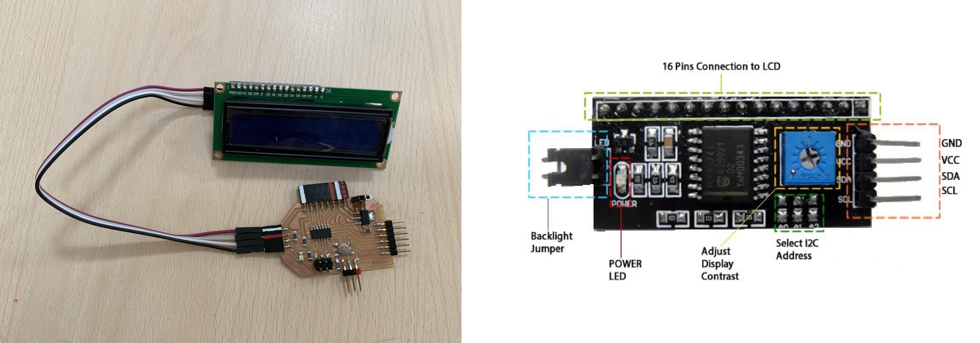
} LCD - I2C
For this example I am going to use an LCD with an I2C communication module. In my case, I bought it through Amazon from AZDelivery, here is the link. This company has a multitude of very interesting tutorials, including that of the LCD module with I2C.
In this case we only need four cables; one for VCC, one for GND, another cable for the SDA and SCL, the I2C connection.
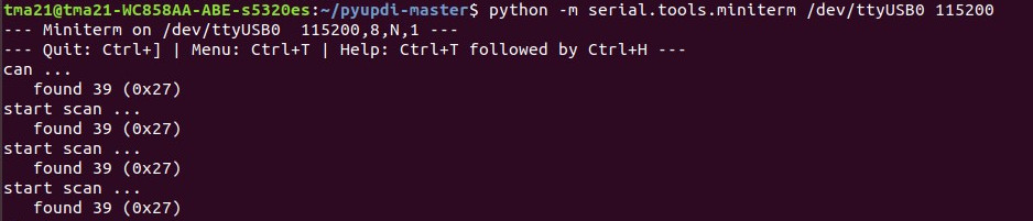
When we use the I2C communication protocol, the first thing we must do is identify the different slaves that we connect to the bus. The same happens when we connect an input or an output, they have to have a name to identify themselves on the bus; is usually 0x... To do this I use Neil's program to see what number the I2C interface of the LCD uses. On this link you can find the addresses of the different input and output modules that use the I2C communication protocol. Below you can see a video of how it works. Recommendation: Download the program from the link, in the text the symbols <> of the libraries are missing.
//
// hello.I2C.ino
//
// I2C hello-world scanner
//
// Neil Gershenfeld 12/8/19
//
// This work may be reproduced, modified, distributed,
// performed, and displayed for any purpose, but must
// acknowledge this project. Copyright is retained and
// must be preserved. The work is provided as is; no
// warranty is provided, and users accept all liability.
//

#include Wire.h

void setup() {
   Serial.begin(115200);
   Wire.begin();
   }

uint8_t address,count;

void loop() {
   count = 0;
   Serial.println("start scan ...");
   for (address = 1; address < 127; address++) {
      Wire.beginTransmission (address);
      if (Wire.endTransmission () == 0) {
         count += 1;
         Serial.print("   found ");
         Serial.print(address,DEC);
         Serial.print(" (0x");
         Serial.print(address,HEX);
         Serial.println (")");
         }
      }
   if (count == 0)
      Serial.println("   no devices found");
   delay(1000);
   }
Once the program is loaded through the UPDI, we connect the LCD to the board and the FTDI to the computer. In the terminal we execute the instruction to see the number on the LCD. Listen the serial port python -m serial.tools.miniterm /dev/ttyUSB0 115200
In my case the number is 0x27.
Once I know what the LCD number is, I go on to test Neil's program, Hello_LCD. Recommendation: Download the program from the link, in the text the symbols <> of the libraries are missing.
//
// hello.LCD.I2C.ino
//
// LCD I2C hello-world
//
// Neil Gershenfeld 12/8/19
//
// This work may be reproduced, modified, distributed,
// performed, and displayed for any purpose, but must
// acknowledge this project. Copyright is retained and
// must be preserved. The work is provided as is; no
// warranty is provided, and users accept all liability.
//

#include LiquidCrystal_PCF8574.h
#include Wire.h

LiquidCrystal_PCF8574 lcd(0x27); // set LCD address 0x27
int count = 0;

void setup() {
   lcd.begin(16,2); // initialize 16x2 LCD
   //lcd.begin(20,4); // initialize 20x4 LCD
   lcd.setBacklight(255); // turn on backlight
   lcd.home(); // go home
   lcd.clear(); // clear display
   lcd.print("Hello World!"); // print text
   lcd.setCursor(0,1); // move cursor
   lcd.print("Count: ");
   }

void loop() {
   lcd.print(count);
   lcd.setCursor(7,1);
   count += 1;
   }
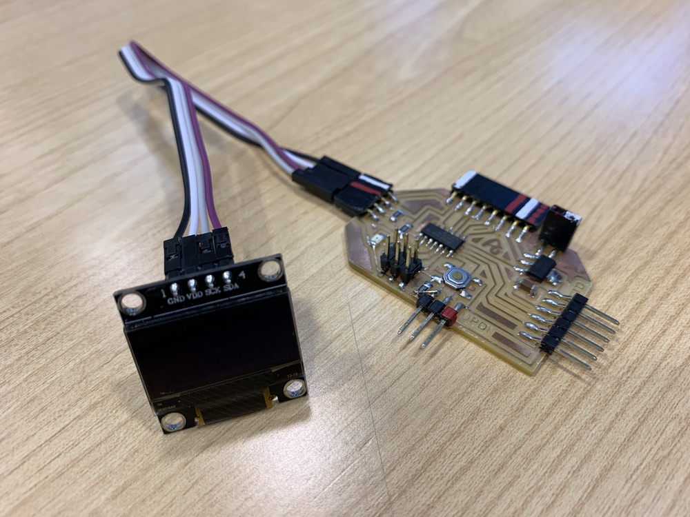
OLED
For this example I am going to use an OLED with an I2C communication module. In my case, I bought it through Amazon from AZDelivery, here is the link. This company has a multitude of very interesting tutorials, including that of the OLED module with I2C.
In this case we only need four cables; one for VCC, one for GND, another cable for the SDA and SCL, the I2C connection.
When we use the I2C communication protocol, the first thing we must do is identify the different slaves that we connect to the bus. The same happens when we connect an input or an output, they have to have a name to identify themselves on the bus; is usually 0x... To do this I use Neil's program to see what number the I2C interface of the OLED uses. On this link you can find the addresses of the different input and output modules that use the I2C communication protocol. Recommendation: Download the program from the link, in the text the symbols <> of the libraries are missing.
//
// hello.I2C.ino
//
// I2C hello-world scanner
//
// Neil Gershenfeld 12/8/19
//
// This work may be reproduced, modified, distributed,
// performed, and displayed for any purpose, but must
// acknowledge this project. Copyright is retained and
// must be preserved. The work is provided as is; no
// warranty is provided, and users accept all liability.
//

#include Wire.h

void setup() {
   Serial.begin(115200);
   Wire.begin();
   }

uint8_t address,count;

void loop() {
   count = 0;
   Serial.println("start scan ...");
   for (address = 1; address < 127; address++) {
      Wire.beginTransmission (address);
      if (Wire.endTransmission () == 0) {
         count += 1;
         Serial.print("   found ");
         Serial.print(address,DEC);
         Serial.print(" (0x");
         Serial.print(address,HEX);
         Serial.println (")");
         }
      }
   if (count == 0)
      Serial.println("   no devices found");
   delay(1000);
   }
Once the program is loaded through the UPDI, we connect the OLED to the board and the FTDI to the computer. In the terminal we execute the instruction to see the number on the LCD. Listen the serial port python -m serial.tools.miniterm /dev/ttyUSB0 115200
In my case the number is 0x3C.
Once I know what the OLED number is, I go on to test Hello_OLED program. You will need to install the Adafruit SSD1306 and GFX libraries. If you need more information you can follow the following tutorial. Another tutorial. Below you can see a video of how it works. Recommendation: Download the program from the link, in the text the symbols <> of the libraries are missing.
/*********
  Rui Santos
  Complete project details at https://randomnerdtutorials.com
*********/
//Fab Academy 2020 - Fab Lab León
//OLED
//Adrianino
//ATtiny1614  - ATtiny1624

#include Wire.h
#include Adafruit_GFX.h
#include Adafruit_SSD1306.h

#define SCREEN_WIDTH 128 // OLED display width, in pixels
#define SCREEN_HEIGHT 64 // OLED display height, in pixels

// Declaration for an SSD1306 display connected to I2C (SDA, SCL pins)
Adafruit_SSD1306 display(SCREEN_WIDTH, SCREEN_HEIGHT, &Wire, -1); // // Reset pin # (or -1 if sharing Arduino reset pin)

void setup() {
  Serial.begin(115200);

  if(!display.begin(SSD1306_SWITCHCAPVCC, 0x3C)) { // Address 0x3C for 128x64
    Serial.println(F("SSD1306 allocation failed"));
    for(;;);
  }
  delay(2000);
  display.clearDisplay();

  display.setTextSize(1);
  display.setTextColor(WHITE);
  display.setCursor(0, 5);
  // Display static text
  display.println("Hello, world!");
  display.setCursor(0, 20);
  display.println("Fab Academy 2020");
  display.println("Adrianino");
  display.display();
}

void loop() {

}
DC Motor
To control a DC motor we will use an H bridge, such as the Allegro A4953. With this driver we can control all types of motors through PWM signals.
In this case, being a component without a module, I create my own. I design and manufacture a small board where I solder the Allegro A4953 driver, a 1uF capacitor, a 10uF capacitor and with the flat connectors where there is no room for mistakes when connecting it. It includes two traces to feed with the 9V battery. I use two digital output of the ATtiny1614 - ATtiny1624 PA4 (Arduino pin 0) and PA5 (Arduino pin 1).
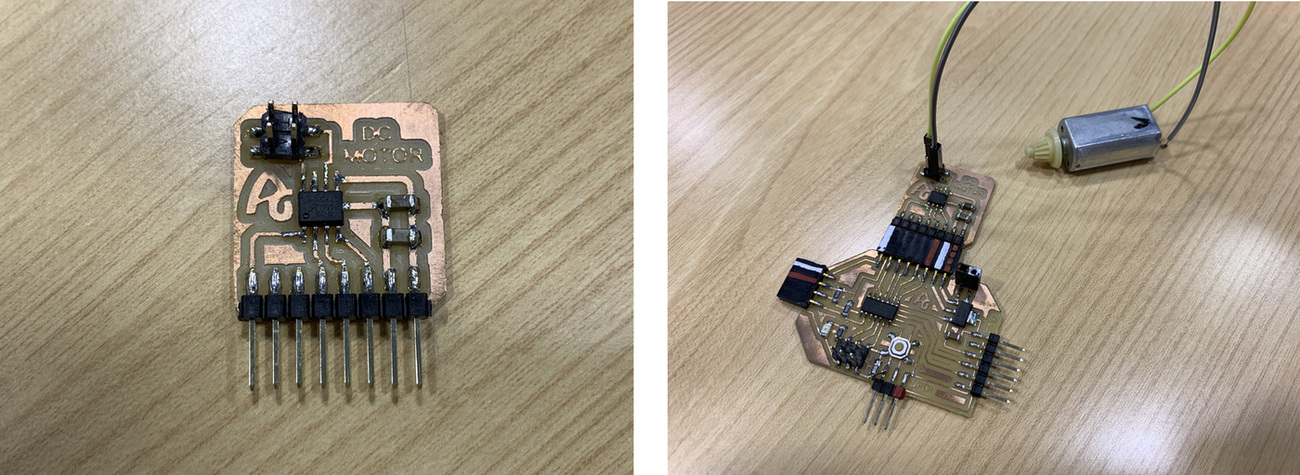
Here you can find the design in Eagle and the PNG's to create the board.

Here you can find a program that moves the motor, but when you press the button it stops, and when you release it, it starts again, accelerating progressively. Here you can find the Arduino file to download. Below you can see a video of how it works.
//Fab Academy 2020 - Fab Lab León
//Motor
//Adrianino
//ATtiny1614  - ATtiny1624
const int switch1Pin = 10;     // switch 1
const int motor1Pin = 0;      // H-bridge pin 0 (in2)
const int motor2Pin = 1;      // H-bridge pin 1 (in1)

void setup() {
    // set the switch pins as input pins and activate their internal pull up resistors
    // so they are not in a floating state because their default state is now HIGH
    pinMode(switch1Pin, INPUT);


    // set H-bridge pins as outputs:
    pinMode(motor1Pin, OUTPUT);
    pinMode(motor2Pin, OUTPUT);
  }

void loop() {
    // if switch1 is pressed, (=LOW because the unpressed 'pulled up' state is HIGH)

  if (digitalRead(switch1Pin) == LOW) {
      analogWrite(motor1Pin, 127); // set pin 1 of the H-bridge to 50% using PWM
      analogWrite(motor2Pin, 0);   // set pin 2 of the H-bridge to low state
    }
     // if neither of the switches are pressed, the motor will stand still
  else
      {
      digitalWrite(motor1Pin, LOW);   // set pin 1 of the H-bridge low
      digitalWrite(motor2Pin, LOW);   // set pin 2 of the H-bridge low
      }
  }
Pump for Softrobotics
During Wildcard Week, one of the things I did was create the Soft Robotics. You can find more information in the Soft Robotics class at the Fabricademy, taught by Dr. Lily Chambers and Adriana Cabrera; as well as the documentation of Montserrat Ciges 😍
To control a Pump we will use an H bridge, such as the Allegro A4953. With this driver we can control all types of motors through PWM signals.
In this case, being a component without a module, I create my own. I design and manufacture a small board where I solder the Allegro A4953 driver, a 1uF capacitor, a 10uF capacitor and with the flat connectors where there is no room for mistakes when connecting it. It includes two traces to feed with the 9V battery. I use two digital output of the ATtiny1614 PA4 (Arduino pin 0) and PA5 (Arduino pin 1).
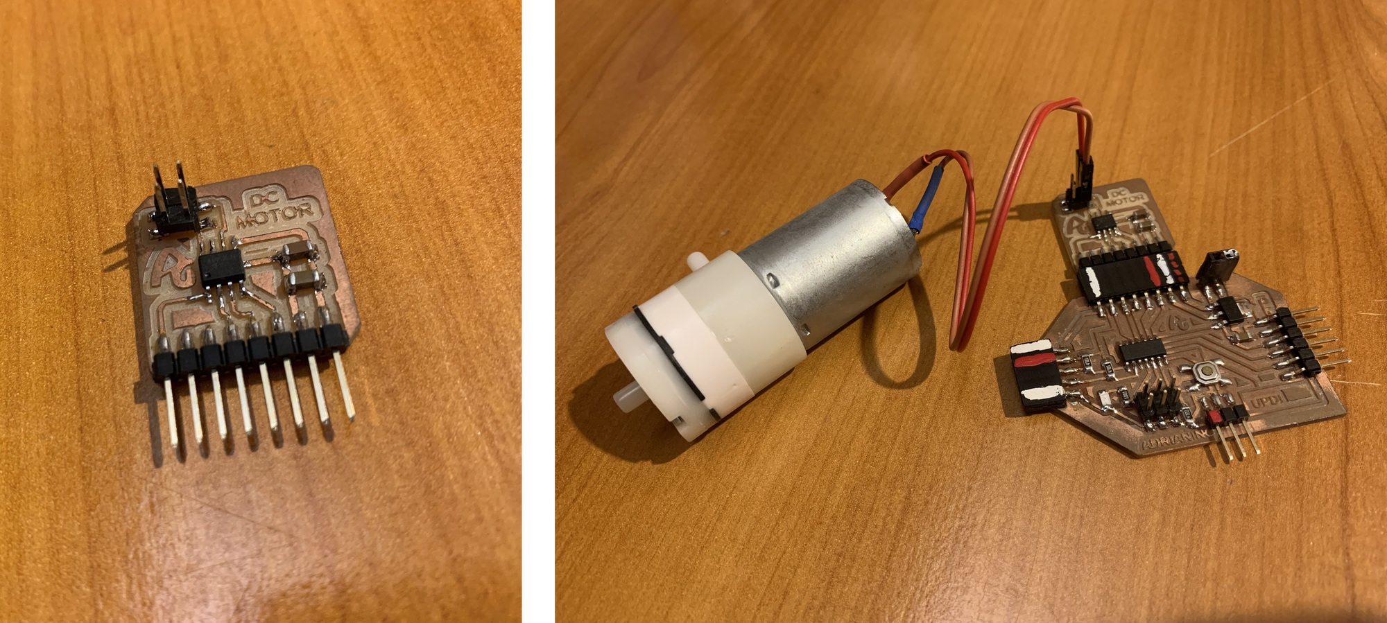
Here you can find the design in Eagle and the PNG's to create the board.
Here you can find a program that moves the motor, but when you press the button it stops, and when you release it, it starts again, accelerating progressively. Here you can find the Arduino file to download. Below you can see a video of how it works.
//Fab Academy 2020 - Fab Lab León
//Soft Robotics - Pump
//Adrianino
//ATtiny1614  - ATtiny1624
const int switch1Pin = 10;     // switch 1
const int motor1Pin = 0;      // H-bridge pin 0 (in2)
const int motor2Pin = 1;      // H-bridge pin 1 (in1)

void setup() {
    // set the switch pins as input pins and activate their internal pull up resistors
    // so they are not in a floating state because their default state is now HIGH
    pinMode(switch1Pin, INPUT);


    // set H-bridge pins as outputs:
    pinMode(motor1Pin, OUTPUT);
    pinMode(motor2Pin, OUTPUT);
  }

void loop() {
    // if switch1 is pressed, (=HIGH because the unpressed 'pulled up' state is LOW)

  if (digitalRead(switch1Pin) == HIGH) {
      analogWrite(motor1Pin, 255); // set pin 1 of the H-bridge to 100% using PWM
      analogWrite(motor2Pin, 0);   // set pin 2 of the H-bridge to low state
    }
     // if neither of the switches are pressed, the motor will stand still
  else
      {
      digitalWrite(motor1Pin, LOW);   // set pin 1 of the H-bridge low
      digitalWrite(motor2Pin, LOW);   // set pin 2 of the H-bridge low
      }
  }
Servo motor
A very common output is a servo. A servomotor is a device similar to a direct current motor that has the ability to be located in any position within its operating range, and remain stable in that position. In this case I use a 0 to 180 degree servo.
In this case we only need three cables; one for VCC, another for GND and another for the signal output that in our case we will connect it to pin PA4 (0 in Arduino). The circuit can be powered by a 9V battery.
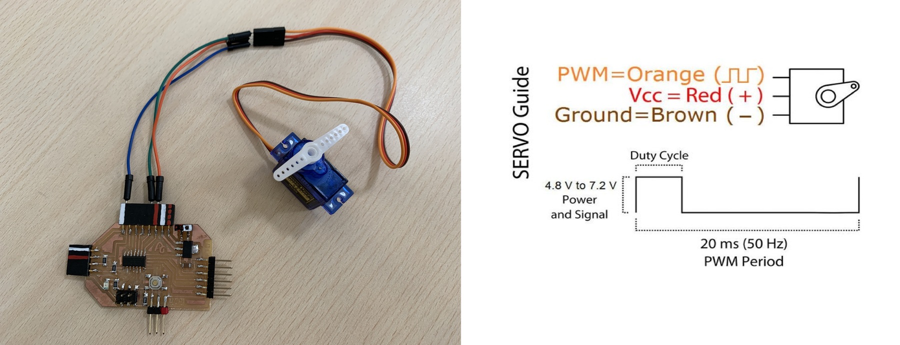
Here you will find the programming to use a servo motor. Here you can find the Arduino file to download. Below you can see a video of how it works. Recommendation: Download the program from the link, in the text the symbols <> of the libraries are missing.
//Original code Elena Cardiel Fab Academy 2019
//Fab Academy 2020 - Fab Lab León
//Servo
//Adrianino
//ATtiny1614  - ATtiny1624

#include Servo.h


Servo myservo;  // crea el objeto servo

int pos = 0;    // posicion del servo

void setup() {

  myservo.attach(0);  // vincula el servo al pin digital PA4

}

void loop() {
   //varia la posicion de 0 a 160, con esperas de 30ms
   for (pos = 0; pos <= 160; pos += 2)
   {
      myservo.write(pos);
      delay(80);
   }

   //varia la posicion de 0 a 160, con esperas de 30ms
   for (pos = 160; pos >= 0; pos -= 2)
   {
      myservo.write(pos);
      delay(80);
   }
}
Stepper Motor
A stepper motor is a motor that we can rotate 360 degrees, and also control its position very precisely through movements of degrees. You can see unipolar or bipolar stepper motors. In the following link you can find more information. In my case I am going to use a NEMA 17 bipolar stepper motor.
To control a stepper motor we will use two H bridge, such as the Allegro A4953.I design and manufacture a small board where I solder the two Allegro A4953 driver, two 1uF capacitor, two 10uF capacitor and with the flat connectors where there is no room for mistakes when connecting it. It includes two traces to feed with the 9V battery (or another power supply). I use the digitals ouputs of the ATtiny1614 - ATtiny1624 PA4 (Arduino pin 0), PA5 (Arduino pin 1), PA6 (Arduino pin 2), PA7 (Arduino pin 3).
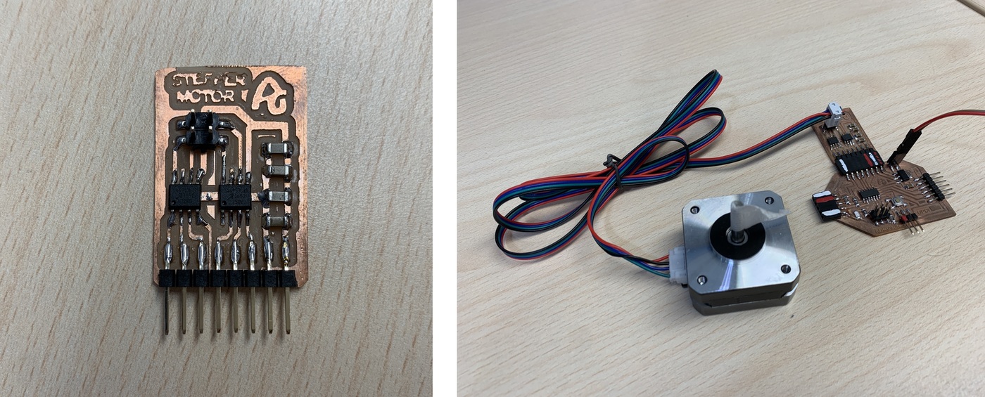
Here you can find the design in Eagle and the PNG's to create the board.
- Stepper Motor Schematic + Board
- Stepper Motor traces and interior

Here you will find the programming to use a stteper motor. Here you can find the Arduino file to download. Recommendation: Download the program from the link, in the text the symbols <> of the libraries are missing. Below you can see a video of how it works.
For the power supply, I use an external 12V 0.6A source. It is also important to know which is each coil, for that we will use the multimeter and measure the resistance ohms of each coil.
Networking and Communicaions
Bluetooth - HC05
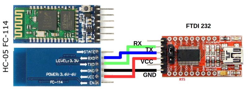
Through an HC-05 module we can connect the Adrianino by Bluetooth and be able to send and receive data through a smartphone or communicate with another board. To use the HC-05 module we will only need VCC(5V), GND, TX and RX. The connection will be made through the FTDI pins, through which we will power the module, as well as communicate with the TX and RX pins.
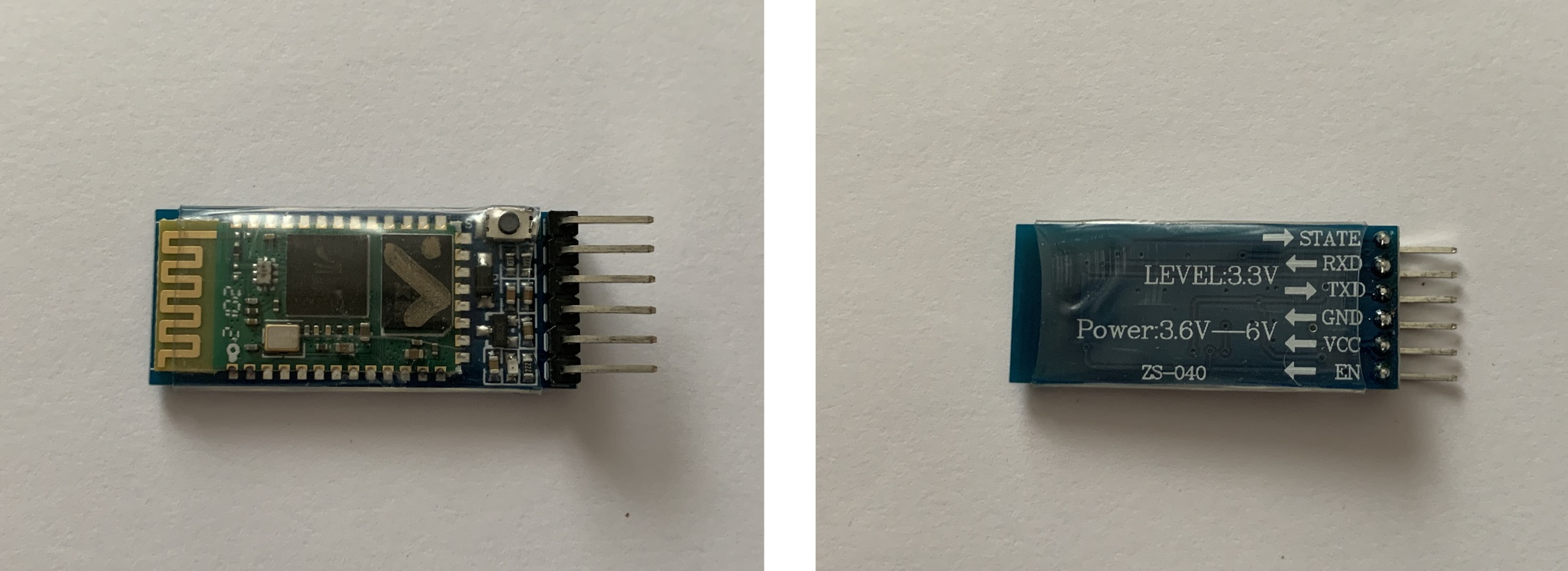
Before connecting the module directly to the Adrianino we must check a list of operations. The HC-05 modules can work as masters or slaves, have different speeds, name or even password. To do this, using an FTDI and the Arduino Serial Monitor, we will verify the following commands that you can find in this document.
The HC-05 modules have two operating modes AT1 (normal mode. Led flashing fast) and AT2 (programming mode. Led flashing slow). By default, when connecting the FTDI and the module to the computer, the AT1 mode works. If, before connecting everything, we keep the small button pressed, we will enter AT2 mode.
We will open the Arduino serial monitor and configure the bottom part, we must choose “Both NL and CR” and the speed “38400 baud” (the speed to communicate in AT MODE 2).To check that the module works, we will write in the AT terminal and it will answer us OK. If not, we must check the above. You can find more information in this tutorial.
If the module is new from the factory and we type the following instructions, the following will come out:
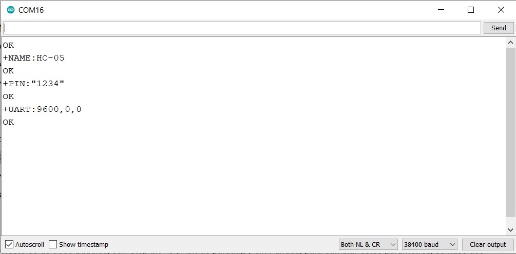
It is important to know these three data, because later we will use them. Above all the speed, it will be at the speed that the module communicates with the Adrianino.
We will load the following program by which we will send values from 0 to 9 and we will blink the LED that is on the PA1 pin (Arduino pin 8). Important not to load the program with the HC-05 module connected. Download the program from the link.
Once everything is configured, we will connect the module to the Adrianino as in the image. VCC with VCC, GND with GND, TX with TX and RX with RX.
I will power Adrianino through the 9V battery. Using a smartphone (it only works with Android) I download the Bluetooth Terminal HC-05 application. This application allows us to scan the devices and we can send simple information. If we want to create a specific application we can use the MIT App Inventor.
Here you can see a video where I connect to the HC-05 bluetooth module and send values to the Adrianino, responding to the LED.
Conclusions
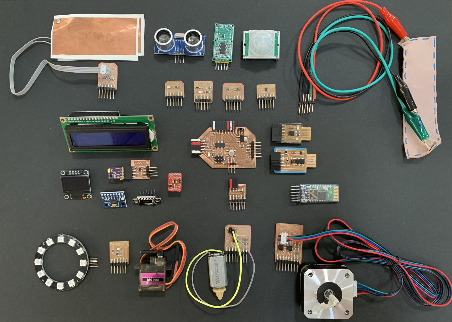
My idea of creating Adrianino has been so that anyone who does the Fab Academy has no fear of electronics. It has the evolution of the UPDI + VCC, which avoids the need to have an FTDI connected to power the board. It is a modular board that everyone can test the different inputs and outputs that appear in the following photo.
PCB Prototype
Once the tests were done on the board, I decided to order PCB's from China to see the final result. I leave here the Gerber file to request more PCB's from any manufacturer. Adrianino Gerber. PCB Prototype. This version of Adrianino has been updated for the new Serial-UPDI converter.
Files
Find below the files that I made for this project.