
Week 06. Electronics Design
Like the previous week, there are two types of assignments, one group and one individual. In my case being alone in the Fab Lab, I do both.
- Use the test equipment in your lab to observe the operation of a microcontroller circuit board (in minimum, check operating voltage on the board with multimeter or voltmeter and use oscilloscope to check noise of operating voltage and interpret a data signal). ✔
- Redraw one of the echo hello-world boards or something equivalent, add (at least) a button and LED (with current-limiting resistor) or equivalent input and output, check the design rules, make it, test it. ✔
- Linked to the group assignment page. ✔
- Documented what you have learned in electronics design. ✔
- Explained problems and how you fixed them, if you make a board and it doesn't work; fix the board (with jumper wires etc) until it does work.. ✔
- Included original design files (Eagle, KiCad, - whatever). ✔
- Included a ‘hero shot’ of your board. ✔
- Loaded a program and tested if your board works. ✔
Like every week, my weekly schedule. 😊

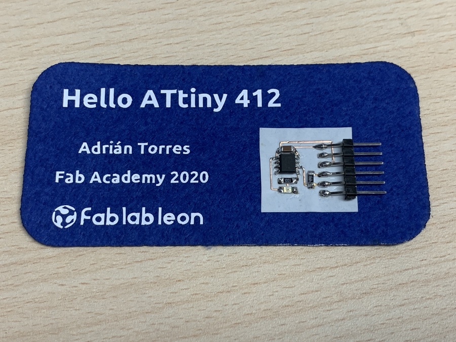
During Week 04 I made my first flexible board with copper vinyl and for this I used Neil's Hello Board with the ATtiny 412. This week I have to design and manufacture my own Hello Board. I hope it works for me.😅
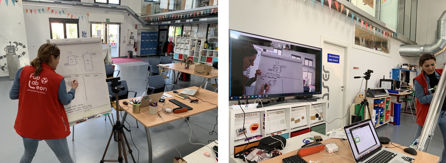
Every Thursday we participate in a Regional Review with the remote students who are in Cartagena to comment on Wednesday's class. This week, Nuria explained basic knowledge of electronic and use of Eagle. Thanks to this, the week is much easier and doubts can be clarified locally. 😇 From here I want to encourage and congratulate you for the great work my colleagues are doing from Cartagena, because distance is complicated and not having a remote instructor with them. 💪
Group Assignment. Test Equipment.
The Group Assignment page is at the following link.
Oscilloscope
In the Fab Lab León we have an oscilloscope purchased to assemble DIY, a DSO Shell 150. I'm going to measure the output of the LED of the Hello Board that Nuria made with the ATtiny 412, because mine being copper vinyl varnish the entire board to protect it. So I regulate the oscilloscope in DC, 2V and a time of 0.2s for each grid. With the clamps I measure between ground and the LED output.

A small video where square waves from 0 to 5V are best appreciated. Exactly the maximum value is 5, 51 V and the minimum value is 2.59 V.
Multimeter
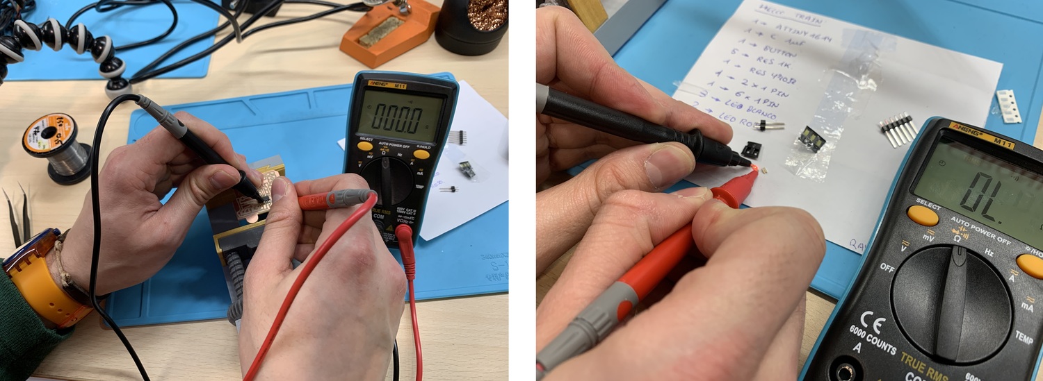
I use a multimeter of the brand Aneng M11 with good quality-price and that we use especially to teach "Jovenes Makers" how to use. I use the multimeter to verify the continuity of the tracks and the polarities of the LEDs. I can also measure capacitors.
Logic Analizer
20/03/2021
During the fall of last year I bought a Logic Analyzer but didn't get to test it until this year. A Logic Analyzer helps us to debug our electronic circuits. It is much more than an oscilloscope, because we can know the information that we send through the FTDI, how an I2C works or simply measure the pulses of a blink and if they correspond to what we have programmed.
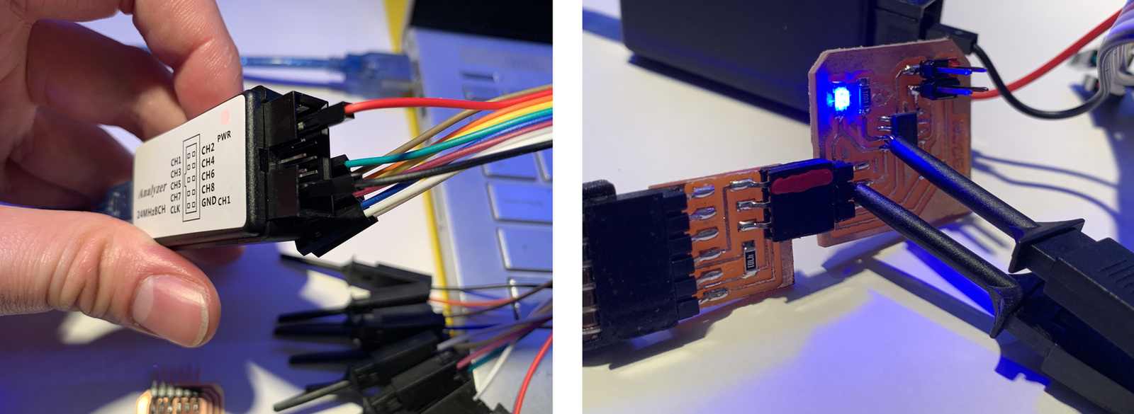
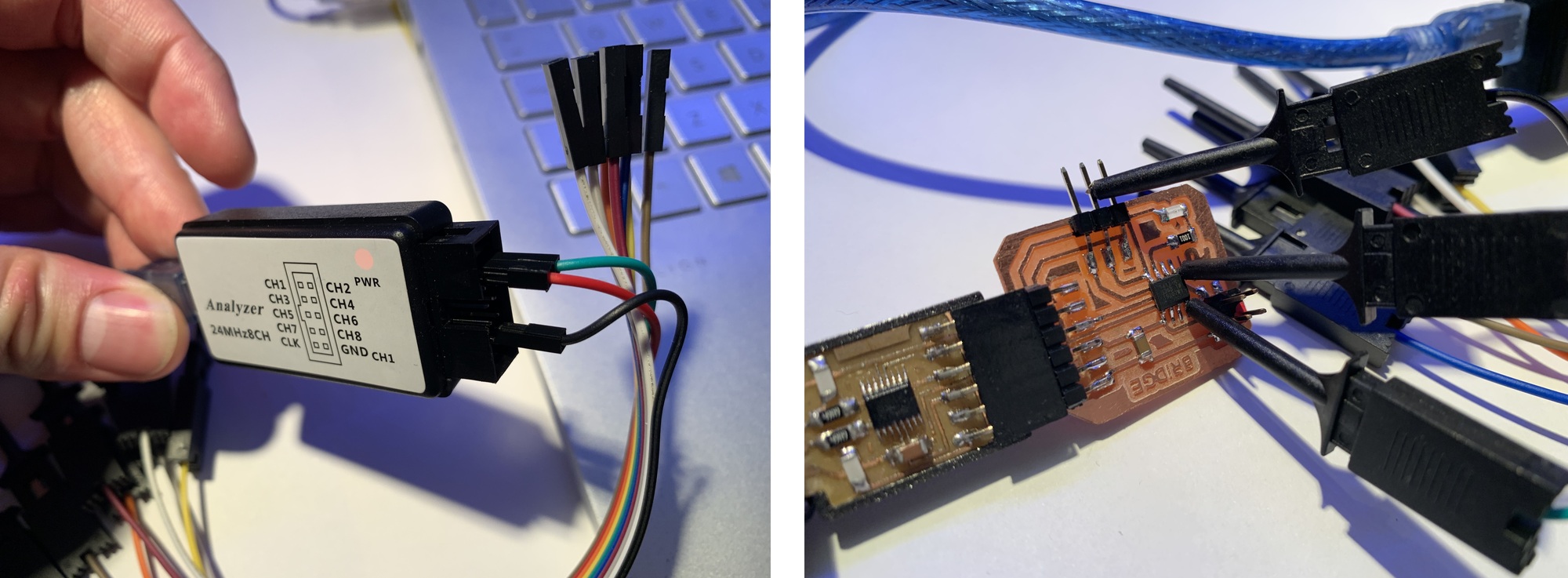
The kit consists of the Logic Analyzer, a USB cable and some female-female cables, but it is better to buy the ones from the following link that have clamps.

To use the Logical Analyzer, we must download the following Saleae brand program (it is used for its logic analyzers such as those of generic brands such as this case). We will install all the steps, when we open the program the following screen will appear where we will be asked to connect the Logic Analyzer. When we connect it, the channels will come out.
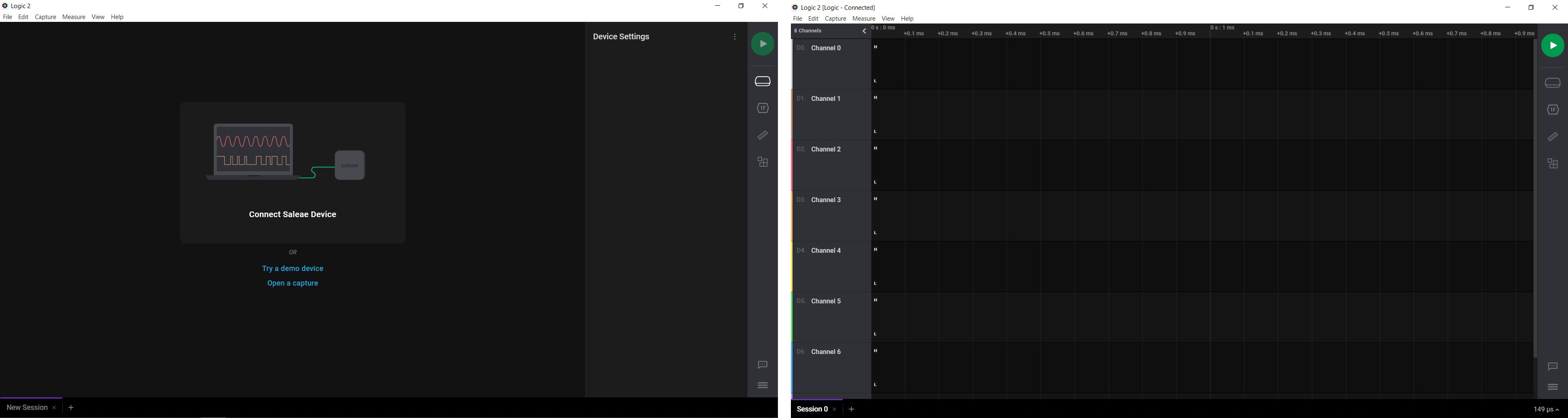
The next step is to configure the channels (we have up to 8 channels). We can configure a channel for Async Serial, I2C, SPI... In my case I am going to configure channel 0 as Async Serial to measure Serial signals (TX, RX) or the pulse of an LED. We have to choose the channel that we are going to measure, in my case it will be channel 0 and with a speed of 115200 (speed that we have configured in the microcontroller to communicate by Serial).
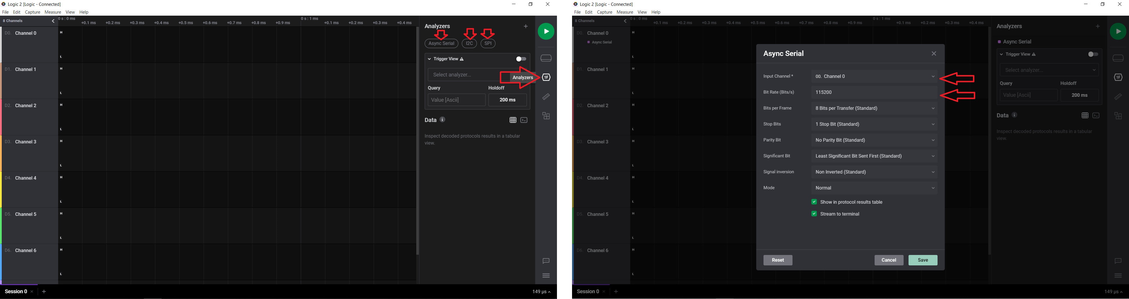
Then we go to the Device Settings tab, where we will configure the Trigger mode (continuously record data until a digital trigger is found). It will be on channel 0 and the capture will last for 1 second.

Once the above is configured, we go to the part of the physical connection. We have to connect a cable to Channel 0 and to GND. The GND will go to the GND (black wire) of the board and Channel 0 (red wire) to the output of the LED pin.
Once connected, we click Play and observe that the timeline advances and stops when the measurement of one second with the Trigger has finished. If we scroll with the mouse, we can see how many pulses we have obtained and, above all, know the time (in my case it coincides with what is programmed by 200 ms Hight, 100 ms Low).

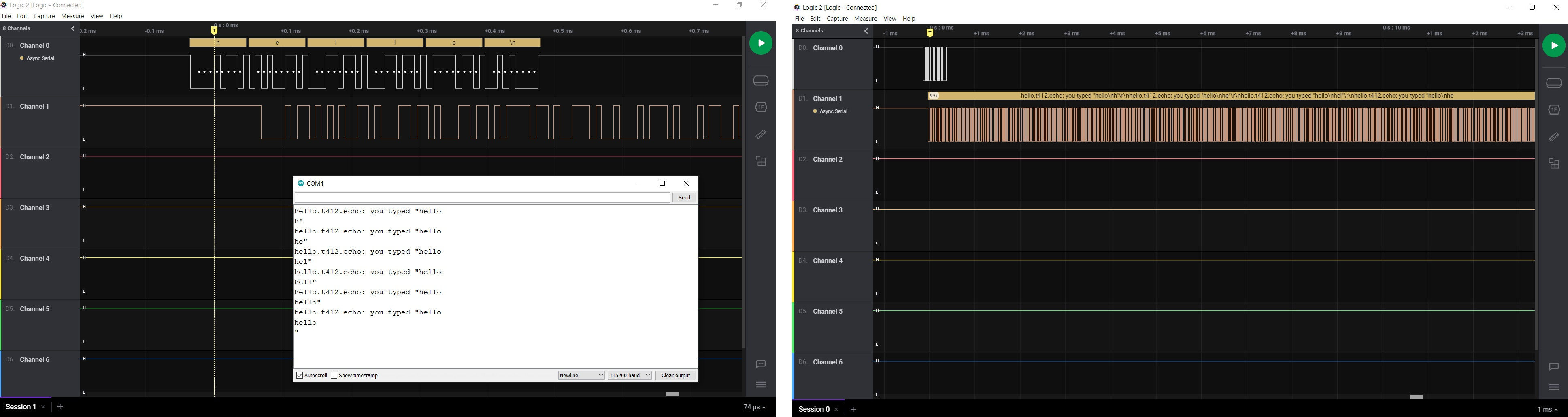
Now I'm going to test Neil's Echo program, to send and receive information from the microcontroller through the TX and RX. For this I am going to configure Channel 0 and Channel 1. Within the analyzer section, we will configure the section to receive in ASCII.

Now we go to the moment of the physical connection, we will connect the GND (black wire) to GND, Channel 0 to TX (red wire) and Channel 1 to RX (green wire).
Once everything is connected, we press Play and from the Arduino Serial Monitor, we write "Hello" and we can see through the Logic Analyzer how it sends the pulses and in ASCII we see the letters "Hello". If we change to Channel 1, we can see how the microcontroller answers us by writing the word "Hello" letter by letter. Something awesome. 🤩
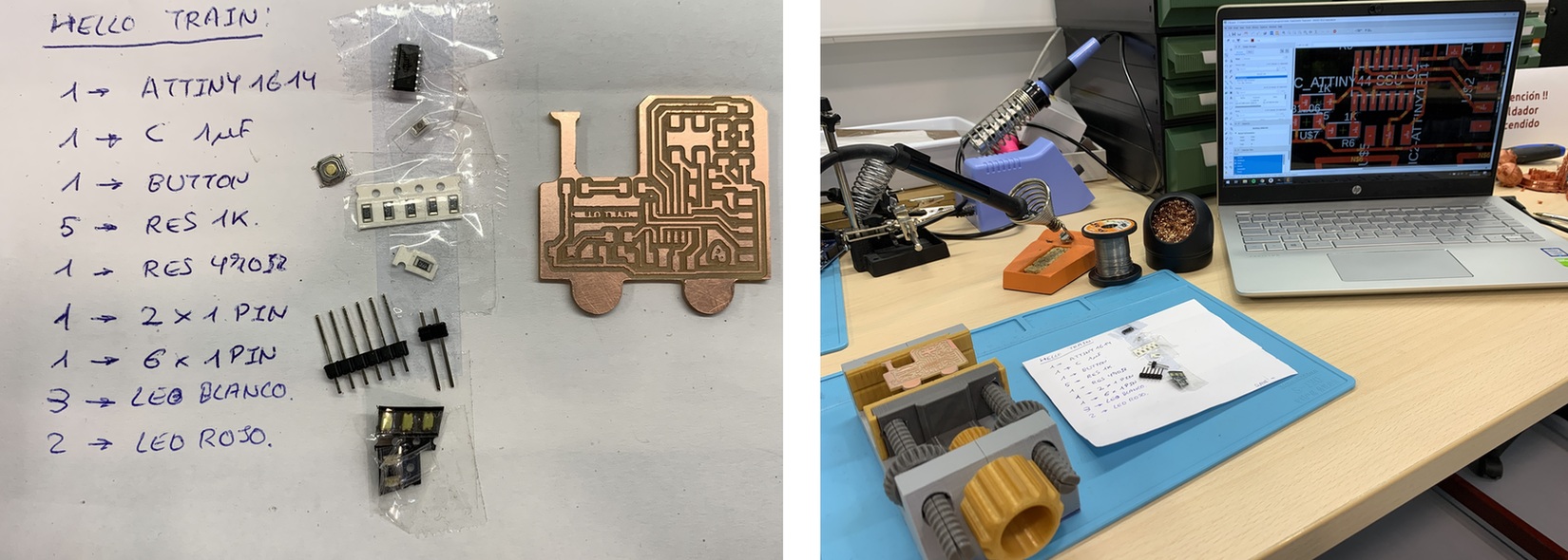
Hello Train.
Eagle
To redesign the Hello Board I will use Eagle. I will use the ATtiny 1614, so I will use the reference of the echo Hello Board ATtiny 1614 from Neil. I will also design the board with a cool shape, I want to make a train machine. I'm looking for the pinning of ATtiny 1614 because I'm going to need it to know where the pins are.
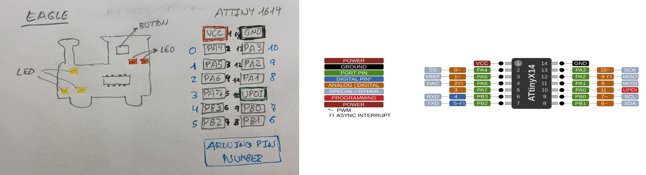
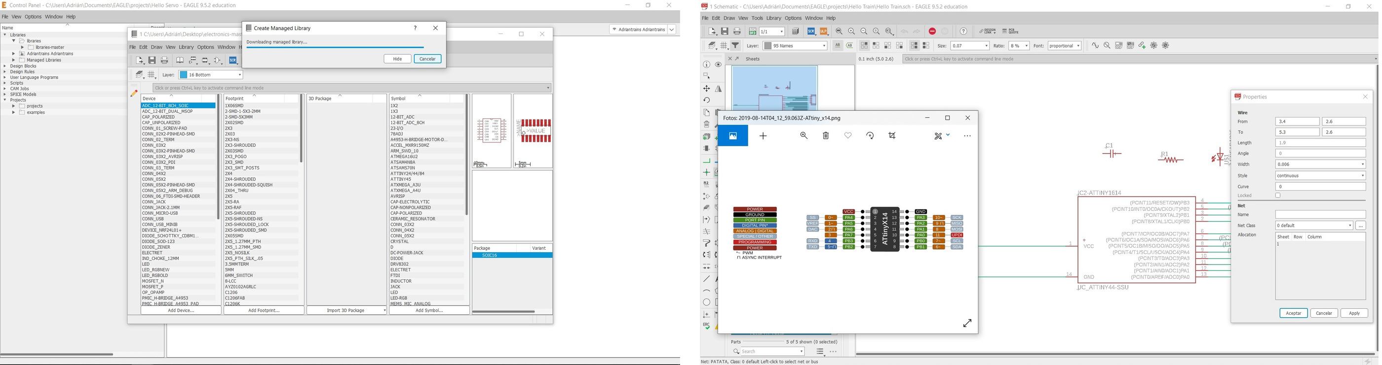
I download the version of Eagle 9.5.2 and the Fab libraries that Neil taught us in class. I create a new project where I can have a schematic and a board. Looking at the Fab library, I find that the ATtiny 412 and the ATtiny1614 are missing. 😰 Nuria had told me that since they are the same encapsulation as the ATtiny 44 and 45 that I make my own component. Thanks Nuria. Through the ATtiny44 and the ATtiny1614 pinout I was creating my own component.
Once I have the ATtiny1614 well pinned, I start adding components. For the button, Nuria explained that there are two ways to place it. With pull-up or pull-down resistance. This means that when we have the button with the contact open, noise can enter through that pin and make us vary the state of that microcontroller input. For this we can put a pull-up resistor that is to say if the button is grounded and a pull-down resistor if the button is connected to VCC. In this scheme both things look good. I am going to use a pull-down resistor.

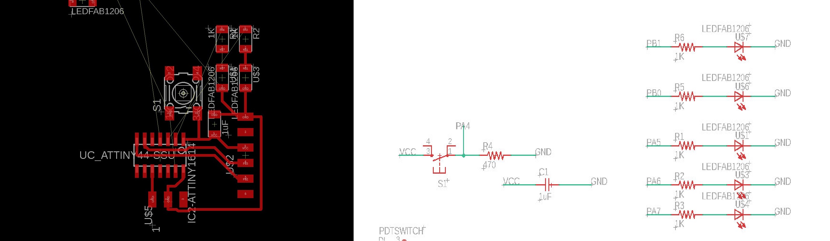
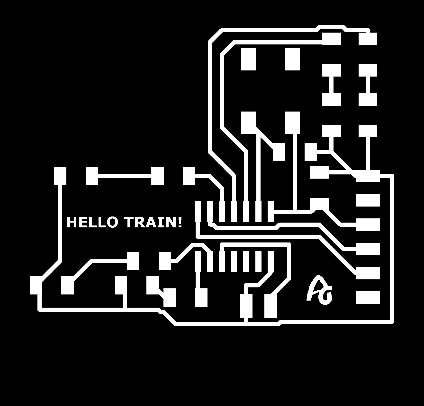
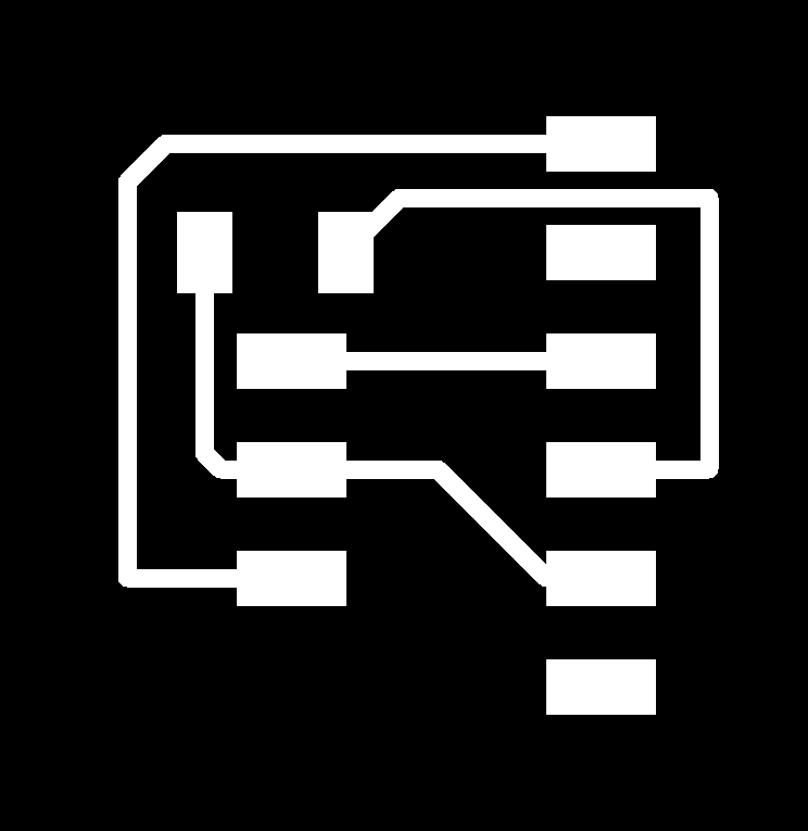
When I have all the components in place and with their corresponding values, I start using Labels. They are much easier to use than wires. Because in the end you have many wires and it is difficult to identify them and you are in danger of creating points of union. So once I have all the labels placed, this is the result of the circuit (I finally added two more LEDs to make the board more beautiful 😊) on pins PB0 and PB1.

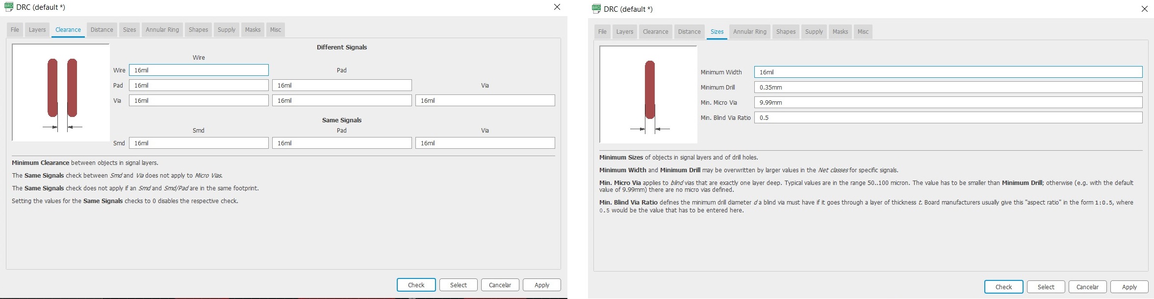
Once I have the scheme, I go on to create the PCB. To do this, click on the icon next to the printer called Board. Automatically all the components that I am going to use are loaded and small yellow lines that are the tracks of the tracks appear. Before starting to join components, I look at which layer I am, the TOP and red (if I made a through hole board, I would have to place myself in the blue BOTTOM layer). Nuria told us that before starting to join the components we must also mark the design rules (DRC), that is, the values of the width of the track and the size of the mill. I put the following values at 16mil. (Nuria later told me that in the same folder where the components library is, there is a file with the design rules).🤣
Once I have the design rules, I begin to orient the components, more or less as I wanted them in the drawing and to make the board smaller. When placing the components I realize that the button will cost me to attach it to the corresponding pin. So I change it in the scheme, from pin PA3 to PA4.
Once I have all the components placed and the tracks together, I have to export the file in .PNG. But first we have to be alone with the tracks, so as I said before we are in the TOP layer, the red layer. Well, you have to turn off all the layers and just turn on the TOP layer. This is found in the Layer Settings option. Once we have only the layer of the tracks we go on to export the design. To do this, the following menu appears in the File -> Export -> Image menu. We have to put the file as Monochrome, 1000 DPI resolution and the area of the Window.

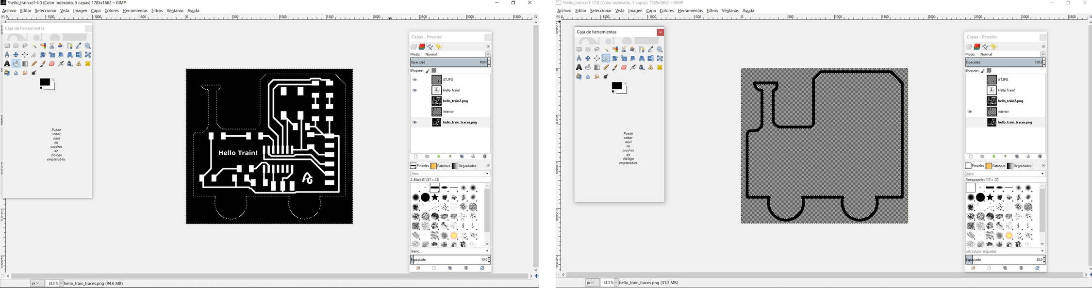
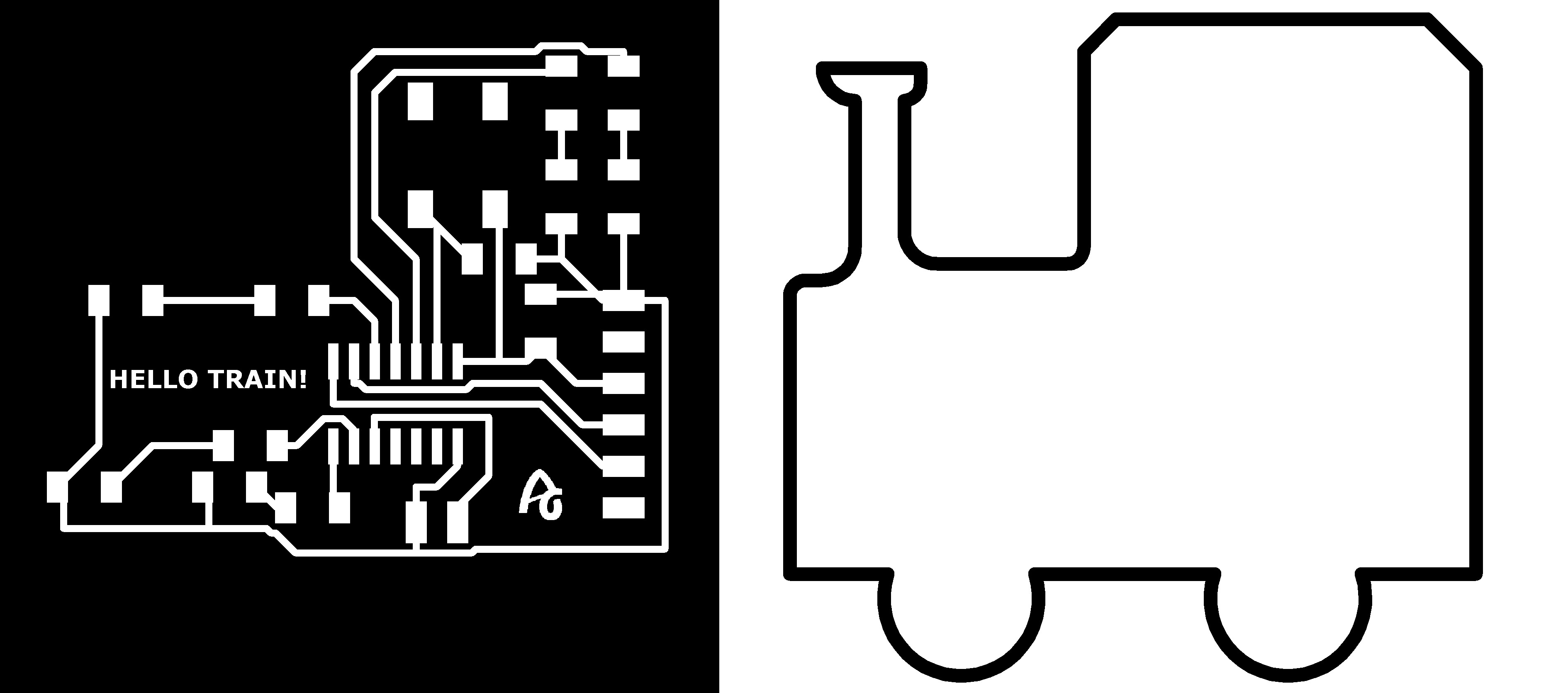
For the outer shape of the board, I will use GIMP. I download a drawing of a train from the internet, I have tried to combine the board with the drawing of the train but I am not able. Besides the outside we have a regular line there are many pixels. So I don't like how it looks.

So thinking, I realize that even from Eagle I can draw the contour to my liking. So I open Eagle again; with the line button, in a line width of 0.8mm (thickness of the mill for the outside) and on the TOP layer I draw the train machine.

I export the .PNG again with the interior tracks and the train outline. I open GIMP and start copying the image to work in different layers. One layer will be the inner traces with letters and my logo (white the tracks and the rest black), and another layer the outer edge (black the cut line and the rest white). With GIMP we can erase the Path that I don't use for the UPDI connector.
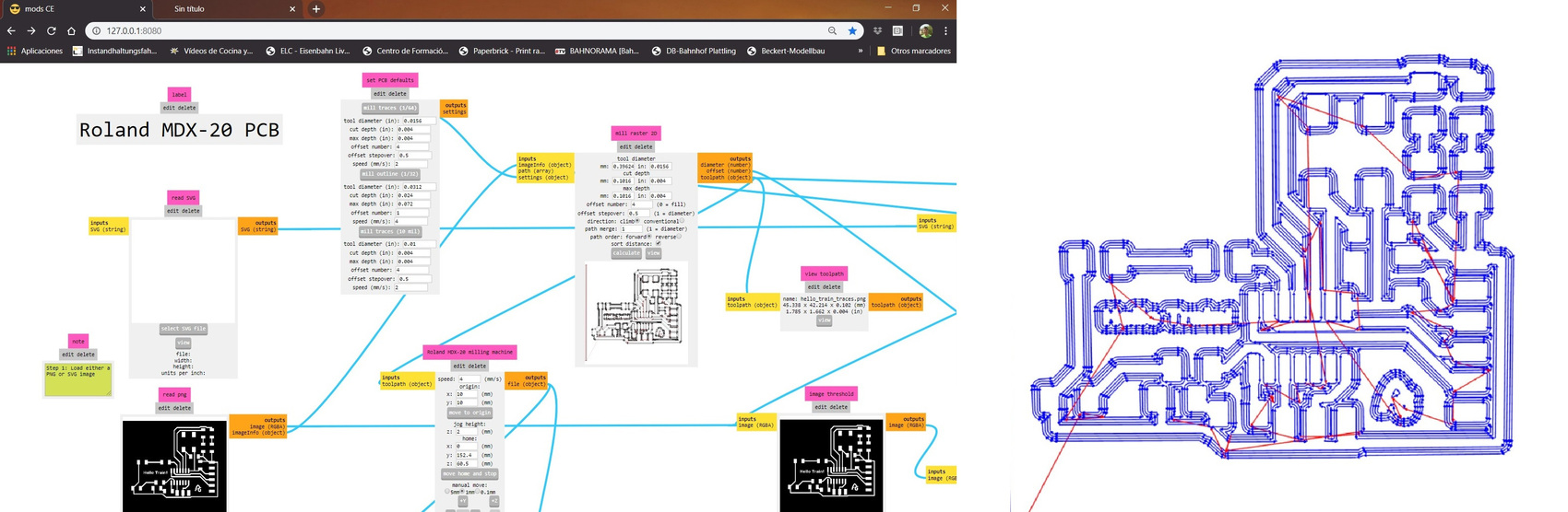
With Mods CE, I simulate the .PNG to see that I can mill all the tracks and not have any problem that there is any track without milling or one with another, especially in the area of the microcontroller.
Well I already have the two .PNG the traces and the outside line. But ... what is the human mind, when I was sleeping😴, I think that I have not correctly verified the position of the UPDI connector and the GND. So the next morning, before going to work I open Eagle, and I realize that it was wrong, I have to reverse the position of the connector.
Once the UPDI connector problem is solved, I export the .PNG again and edit it with GIMP to get the trace and interior file. Here are the links of the .PNG and the Eagle files.
ROLAND MDX-20A MODELA + MODS CE
As during Week 04, I use the Roland Model MDX-20A and Fran's Mods CE again. I import the .PNG of the traces and use the mill 1/64 at a speed of 1 mm / s. The X = 25 and Y = 1.
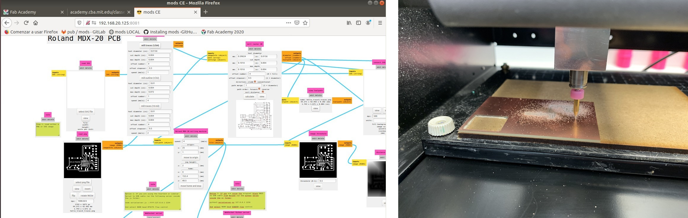
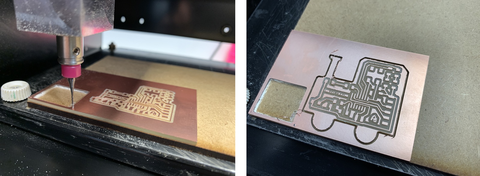
While I was milling the Model, I observe that in the front, it hardly deepens, but in the back it is doing well 😬. The sacrificial board is slightly inclined. It also happens to me for being a little "ruinas" (spanish expression that you save and spend nothing). So once it finishes milling, I lower the mill a little more and end up milling perfectly.
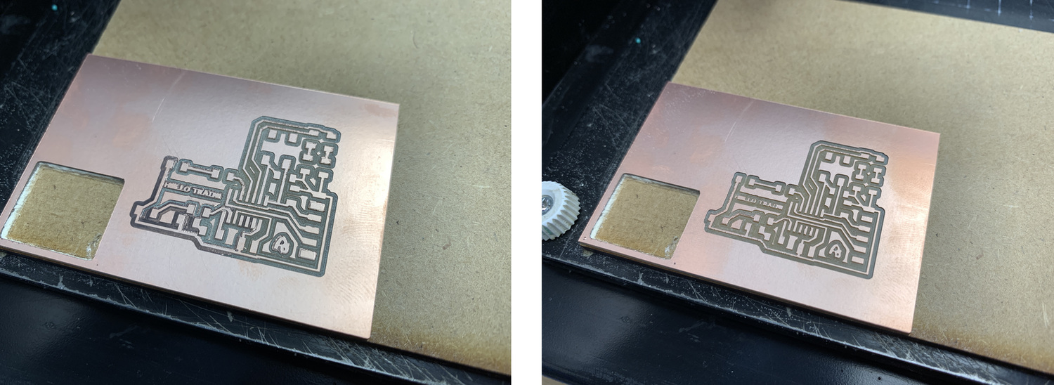
To cut the board, change to mill 1/32, at a speed of 1 mm / s. When I was milling, I notice that he begins to cut the wood of the sacrificial board, so I stop work. I tell Nuria, and she tells me that it may be because in Mods CE, the parameter of the Z is 2 mm and the boards are 1, 9 mm.
Components and tin soldering
Once I have the board milled, I pick up the components of the Fab Lab León inventory. And with patience, good light and the computer to follow the scheme and the position of the components start soldering. 😇
A small time-lapse of the soldering process. I had to use the vacuum solder to remove some tin from two pins of the ATtiny1614. Through the multimeter I check the welds and the polarity of the LEDs.
And this is the final result, a very very choo choo train. 🚂 🚂 🚂 😍

Programming the Hello Train ATtiny 1614
To program the board I need to create a program in Arduino, that when I press the button I create a sequence of lights. The first thing I have to do is configure the pins of the inputs and outputs. I want the sequence of lights to be pressed when the button is pressed, the state of that button is 0. Using an If / else conditional I do the sequence.
Here is the Arduino program to download.
//Adrián Torres - Fab Academy 2020 - Fab Lab León
//tiny1614 hello_train
//
//Original code:Neil Gershenfeld 12/8/19
// This work may be reproduced, modified, distributed,
// performed, and displayed for any purpose, but must
// acknowledge this project. Copyright is retained and
// must be preserved. The work is provided as is; no
// warranty is provided, and users accept all liability.
//
const int ledPin1 = 3;//first light
const int ledPin2 = 6;//white light
const int ledPin3 = 7;//white light
const int ledPin4 = 1;//red light
const int ledPin5 = 2;//red light
const int buttonPin = 0;// button pin
int buttonState = 0;//initial state of the button
int i = 0; //variable intensity led

void setup() { //declaration of inputs and outputs
  pinMode(ledPin1, OUTPUT);
  pinMode(ledPin2, OUTPUT);
  pinMode(ledPin3, OUTPUT);
  pinMode(ledPin4, OUTPUT);
  pinMode(ledPin5, OUTPUT);
  pinMode(buttonPin, INPUT);
}
void loop() {
  buttonState = digitalRead(buttonPin);// we read the state of the button
  if (buttonState == HIGH) { //if we press the button
  digitalWrite(ledPin2, HIGH);
  digitalWrite(ledPin3, HIGH);
  delay(2000);
  digitalWrite(ledPin4, HIGH);
  digitalWrite(ledPin5, HIGH);
  delay(2000);
  digitalWrite(ledPin1, HIGH);
  delay(5000);
  digitalWrite(ledPin1, LOW);
  delay(1000);
  digitalWrite(ledPin4, LOW);
  digitalWrite(ledPin5, LOW);
  delay(2000);
  digitalWrite(ledPin2, LOW);
  digitalWrite(ledPin3, LOW);
  delay(1000);

}
  else {  //if we don't press the button
  digitalWrite(ledPin1, LOW);
  digitalWrite(ledPin2, LOW);
  digitalWrite(ledPin3, LOW);
  digitalWrite(ledPin4, LOW);
  digitalWrite(ledPin5, LOW);
  }
}
To upload the code to the board I will perform the following process with Linux.
- 1. I open the Hello_train_button_led program in Arduino. I select the ATtiny 1614 and 20Mhz internal Crystal board. I check it, compile it and save it (save it in .hex and .ino).
- 2. I copy the Hello_train_button_led.ino.hex file into the pyupdi folder.
- 3. I run dmesg -w
- 4. I use the USB-FT230XS-UPDI that Nuria created. Connect and disconet the ftdi cable and take note of the "port name" ttyUSB0
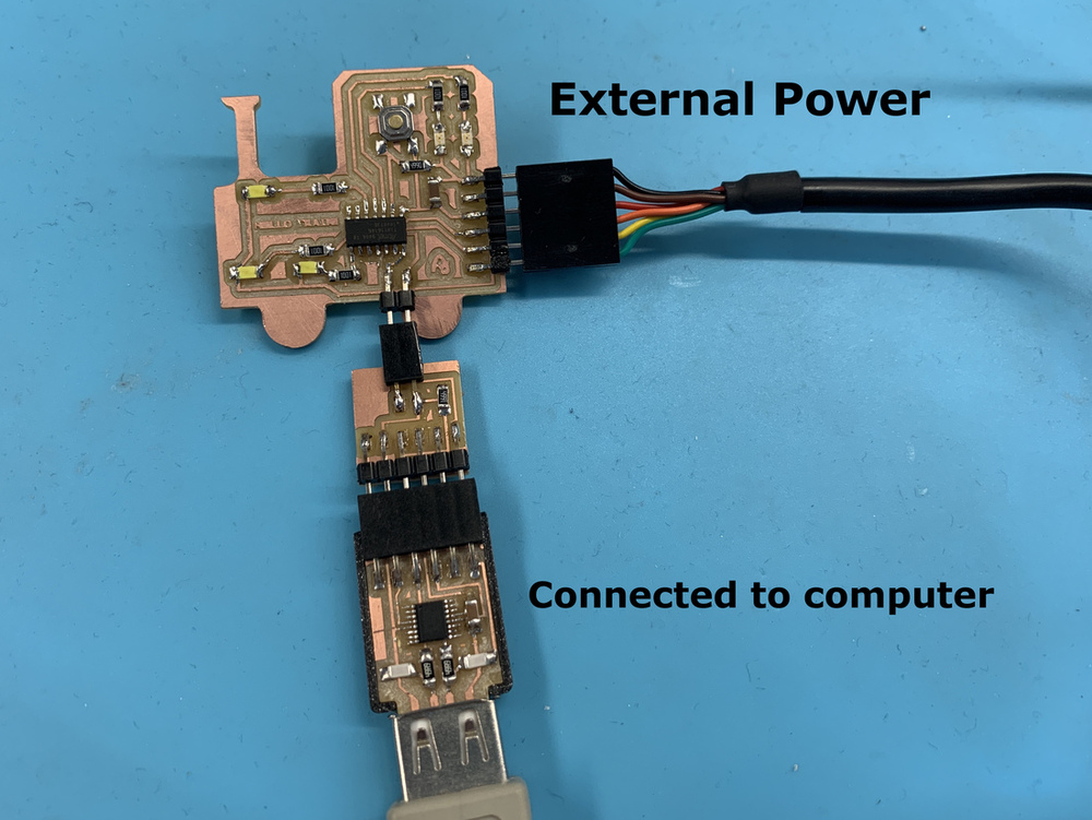
- 5. I connect the boards as follows. USB-FT230XS-UPDI + hello_train + USB-Serial-FT230X (this just for power and ground).

- 6. Go into the "pyupdi" folder.
- 7. Program the board using python -> run sudo python3 pyupdi.py -d tiny1614 -c /dev/ttyUSB0 -b 19200 -f Hello_train_button_led.ino.hex -v
Apparently something is not going well, try loading the .hex file but stop and close the ttyUSB0 port.

So since two weeks ago my Hello Board ATtiny412 programmed it with my USB-SERIAL FT230X, I need to solder the UPDI converter to FTDI. Thanks to Nuria who is cautious, when she made her USB-FT230XS-UPDI she milled the Serial-UPDI.FT230X. 😘
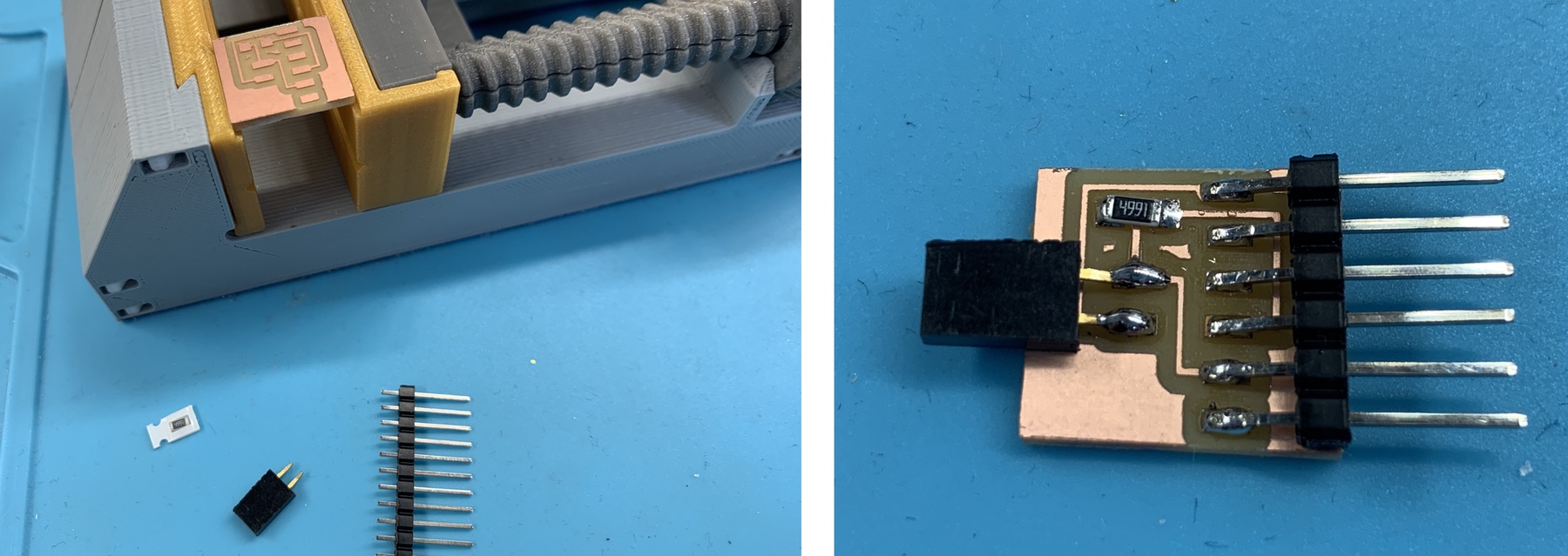
Once soldered, I connect it as follows. USB-Serial-FT230X + Serial-UPDI.FT230X + hello_train + USB-FTDI (this just for power and ground).
I repeat all the steps to program.
- 1. I open the Hello_train_button_led program in Arduino. I select the ATtiny 1614 and 20Mhz internal Crystal board. I check it, compile it and save it (save it in .hex and .ino).
- 2. I copy the Hello_train_button_led.ino.hex file into the pyupdi folder.
- 3. I run dmesg -w
- 4. I use the USB-Serial-FT230X. Connect and disconnet the ftdi cable and take note of the "port name" ttyUSB0
- 5. I connect the boards as follows.USB-Serial-FT230X + Serial-UPDI.FT230X + hello_train + USB-FTDI (this just for power and ground).
- 6. Go into the "pyupdi" folder.
- 7. Program the board using python -> run sudo python3 pyupdi.py -d tiny1614 -c /dev/ttyUSB0 -b 19200 -f Hello_train_button_led.ino.hex -v
Now it works, here is a small video of the loading process and the operation when I press the button on the board. 🚂 🚂 🚂 😍
Case for Serial-UPDI.FT230X
With Rhinoceros I design a small 3D printed case so that the connectors are not in the air. I leave both designs. Case USB-Serial-FT230X and Case Serial-UPDI.FT230X

Other software
Kicad
As Neil recommended us to try other EDA softwares, I will try to use KiCAD. For this I download the sftware and libraries. When designing the schematic, I will use the ATtiny412, 3 LEDs, 1 button to create a traffic light or signal. For this I also use the labels, which is much easier and cleaner schematic.

When creating the board it is a bit complicated, because we must first generate the list of networks. Then we assign the footprints to the symbols of the scheme. At this moment I get an error with the footprint libraries.
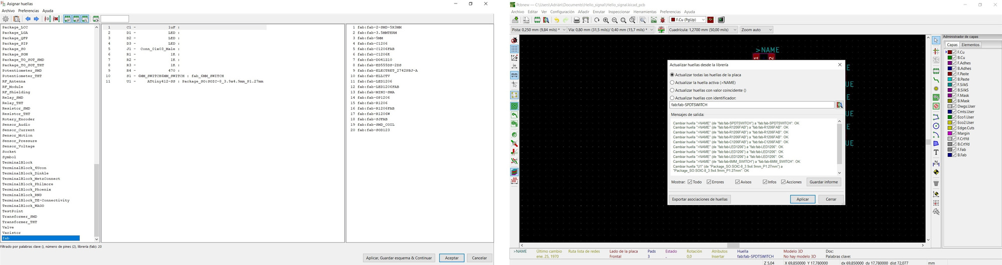
I try to add them manually, but I still can't get all the footprints. It seems that it does not find the relationship between the component and its footprint. So I only get the ATtiny 412 and an LED (that LED does not have its connection with the ATtiny). So I don't know why this happens to me. 😰

EasyEDA
As I could not finish the design with KiCAD I decided to try another software, EasyEDA. As soon as you start it you can follow a series of tutorials to create or modify boards. It is very intuitive and has many components in the libraries. So I look for the ATtiny412 and they have it. One of the interesting things is that you can bookmark your most used components. It’s cool.

The supplies must be wired, it is not worth using Labels directly, so the ATtiny wired it and the rest of the components I put the Label with GND or VCC. The pins that we don't use must be marked with a cross, but we will have an error.
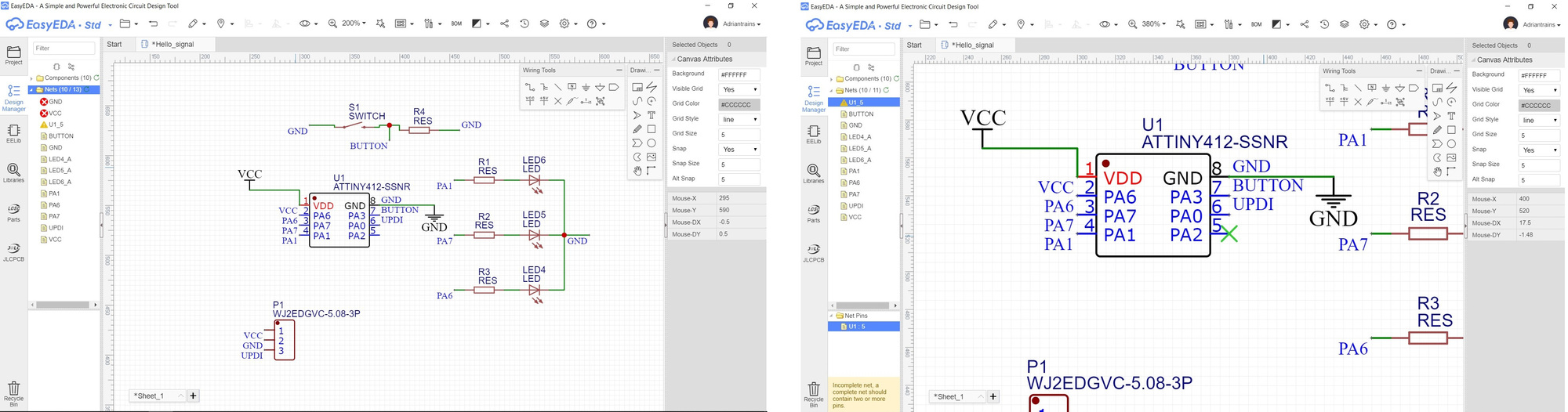
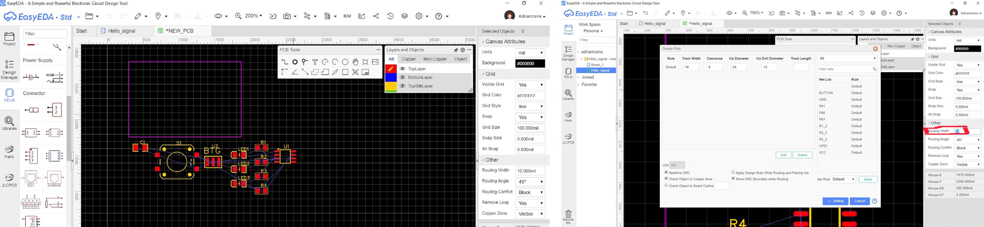
When we start to make the board, this is how the components appear. In the design rules we will put 16 routing size and track width.
Using the Board Outline layer (purple layer), draw the outside of the board. One of the things I like about EasyEDA is that you can simulate the 3D board finish (and it is valid for single trace or multitraces boards) Incredible. 😲
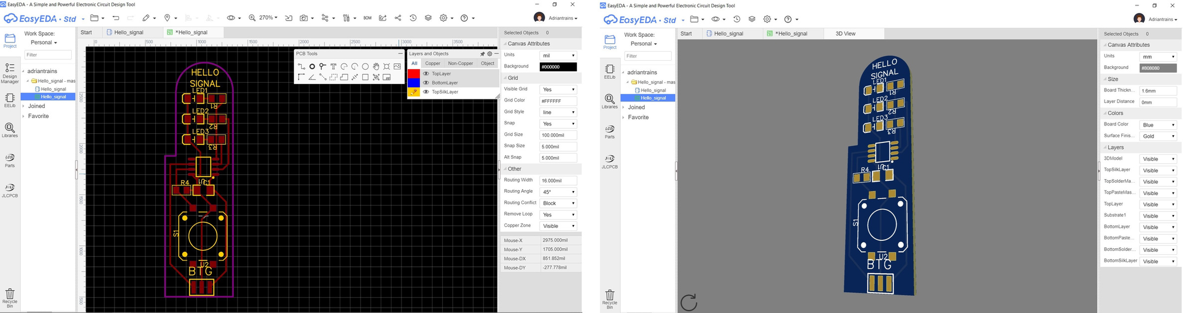
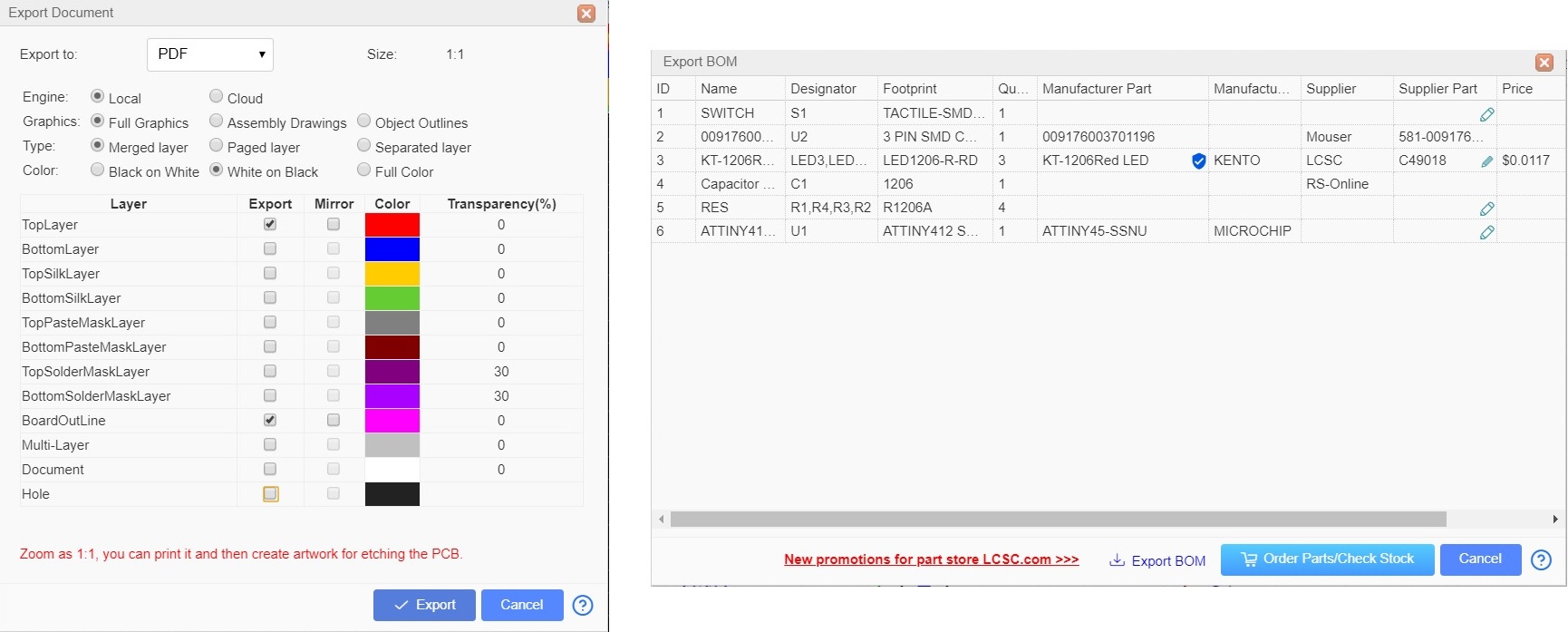
When exporting the design we can do it in PNG, SVG or PDF. The first thing I do is export it in PNG, but it looks very small and like the pixels are very large and irregular. I try to export it in PNG but increased by 2x; It looks something better. Pablo tells me that it may be the DPI, which is why it is very small and granulated. Try to export it in PDF. In PDF much better, thanks Pablo. 🤗
Another interesting thing about EasyEDA is that you can create the BOM list with all the materials you need and buy them directly.
Here are the EasyEDA files and the PDFs with the traces and the inside of the board.
Upverter
My friend Marta Verde has shown me another PCB design program that can be interesting. Upverter
Adrianino
08/09/2020
Although I have already finished my Fab Academy, I am still researching. Speaking with my instructors Nuria and Pablo, I told them that I wanted to continue working on the Hello World project, but I was not satisfied with making a board for each sensor or actuator.
So I decided to make a board with the ATtiny1614, where I could use the maximum pins for the inputs or outputs; that had external power; I2C connection. The idea is that a student can test as many sensors as possible, become familiar with electronics and programming little by little. And the Adrianino was born.
Furthermore, I wanted to go one step further and place a VCC pin next to the UPDI programming pins, which I will explain later on how it works. This version of Adrianino has been updated for the new Serial-UPDI converter.

Features
- This board has FTDI and UPDI + VCC connection to program it without the need for external power (or the FTDI).
- It contains a voltage regulator to power the board with a power supply (9V battery).
- It has another 9V power connection to for example power a DC motor driver.
- Then there are 4 outputs or inputs with VCC and GND on each side to be able to connect different inputs or outputs.
- On the left there is an I2C connection to connect an LCD, OLED or a sensor that uses this communication.
- There are 3 outputs or inputs at the bottom and with a GND pinout.
- There is an LED and an integrated button, which will help us to test that the microcontroller works with a simple program.
- Through the FTDI connection we can read the data from the different sensors through the Serial.
BOM and Schematic
This is the schematic where you can see all the components.

Adrianino |
Where to buy? | Amount | Price | Total price |
| Proto Board FR1 | Digikey | 1/4 board | 1,24 €/unit | 0,31 € |
| ATtiny1614 | Digikey | 1 | 0,64 €/unit | 0,64 € |
| 1uF capacitor 50V | Digikey | 1 | 0,18 €/unit | 0,18 € |
| 4,99kΩ resistor | Digikey | 2 | 0,09 €/unit | 0,18 € |
| 499 Ω resistor | Digikey | 1 | 0,09 €/unit | 0,09 € |
| IC Regulator 5V 1A SOT223 | Digikey | 1 | 0,43 €/unit | 0,43 € |
| 1kΩ resistor | Digikey | 1 | 0,09 €/unit | 0,09 € |
| LED | Digikey | 1 | 0,35 €/unit | 0,35 € |
| Button | Digikey | 1 | 1,00 €/unit | 1,00 € |
| SMT RT Angle Male Header 0.1" (36pos) | Digikey | 9 | 0,15 €/unit | 1,35 € |
| Female 1 row horizontal header | Digikey | 14 | 0,15 €/unit | 2,10 € |
| Male 2 row vertical header | Digikey | 3 | 0,20 €/unit | 0,60 € |
| Total cost | 7,32 € |
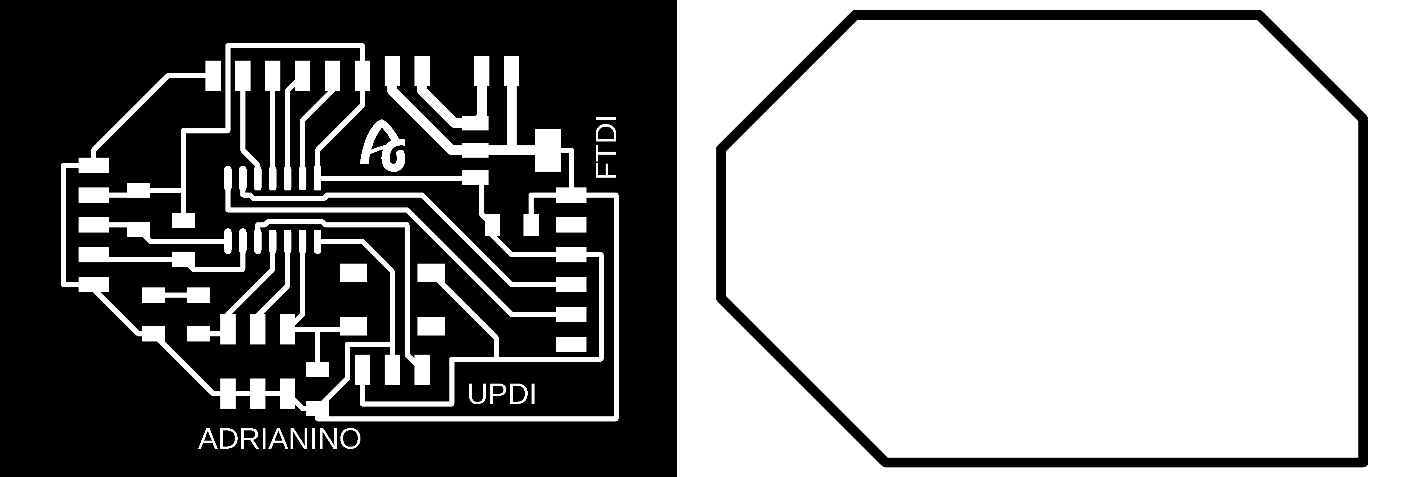
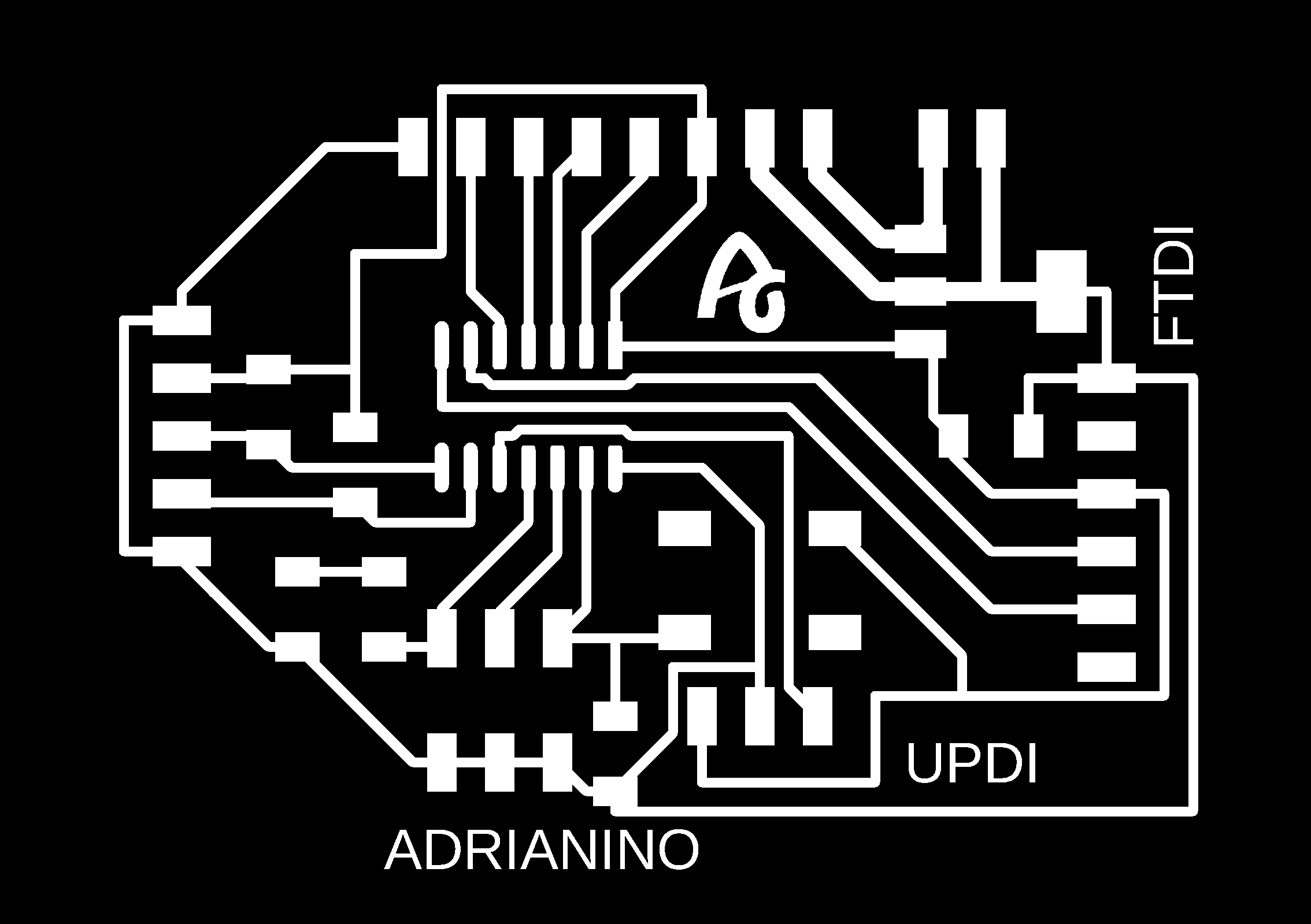
Board design
In the files section you can download the Eagle files and the PNG's. Here is a sample of the PNG's, traces and cutting lines.
Programming
The new generation of ATtiny's are programmed through UPDI, for more information on the process you can follow my documentation of the week Embedded Programming.
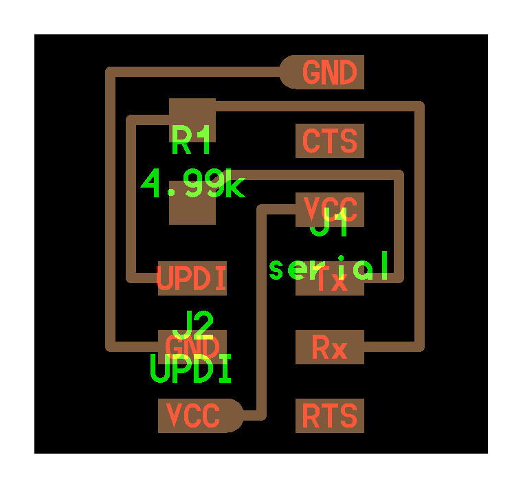
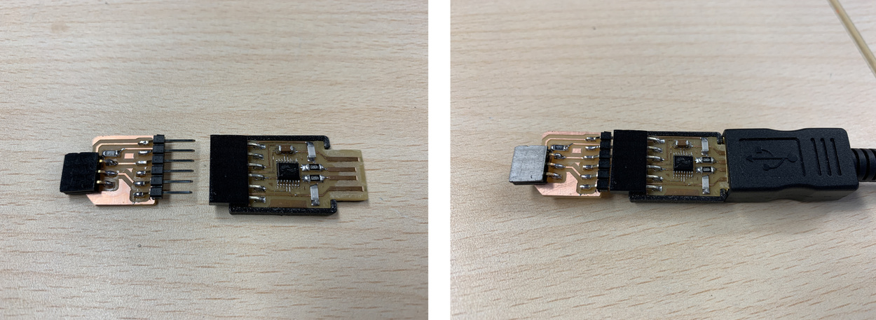
UPDI + VCC module. Old version.
At the time of programming, until now I used the Hello USB-serial.FT230X + Hello serial-UPDI.FT230X and also the power supply of the board with an FTDI (which later helps us to read through the Serial).
With this adapter we have the Serial + UPDI + VCC adding a higher pin, without the need to use another FTDI to power the board.
Schematic and board design
The design is the same as the one Neil uses, except that I add the Vcc pin to power the board that we programmed.

In the Files section you will find the PNG's and the Eagle file to download them.

Operation
The connection is very simple, we only need the FTDI-USB and we connect the UPDI + VCC module to the board, in this case to the Adrianino that has the three pins (UPDI + GND + VCC).

In the following video you can see the programming process of the Adrianino and an LCD.
Conclusions
With this evolution, we managed to program through UPDI without the need for external power from another FTDI.
Files
Find below the files that I made for this assignment.