

Index
Introduction
After making the Fab-Xiao, my colleague Nuria Robles was thinking about using the Xiao for Fabricademy. The idea was to have a microcontroller that was easier to program than the ATtiny45 or the commercial Lilypad.
So after several tests and trials, the FabriXiao was born. You can use a Seeed Studio Xiao RP2040 model or a Seeed Studio Xiao ESP32-C3 if you want a bluetooth or wireless connection.
For this I want to document the process of creating a dev board and several examples of inputs and outputs with this board.
History
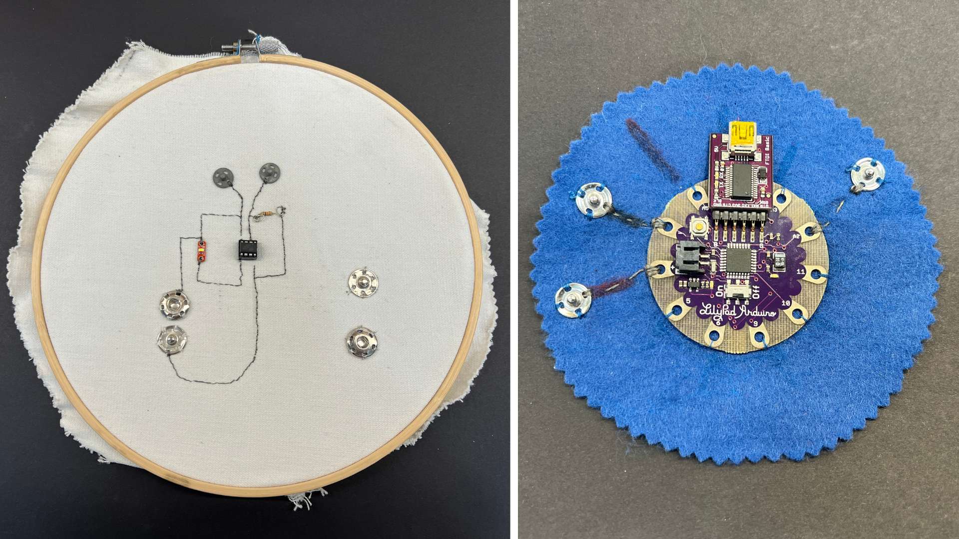
As I mentioned before, the evolution of textile electronics at the Fabricademy has had several phases. The use of the small ATtiny45 microcontroller programmed with tweezers or the Lilypad Arduino using an FTDI to program it. This made it more complex for students to program and assemble their e-textile circuit. Here I show two examples created by Nuria Robles..
During 2023, the new family of Seeed Studio microcontrollers, the Xiao, was introduced at the Fab Academy. That's why in my case I designed and manufactured the Fab-Xiao. When Nuria saw it, she thought it was a good idea to use it in the Fabricademy. That's how the two of us designed a first prototype to be manufactured in the Fab Lab. That year, Nuria recommended her student Ieva Marija to use the Xiao for her final project.
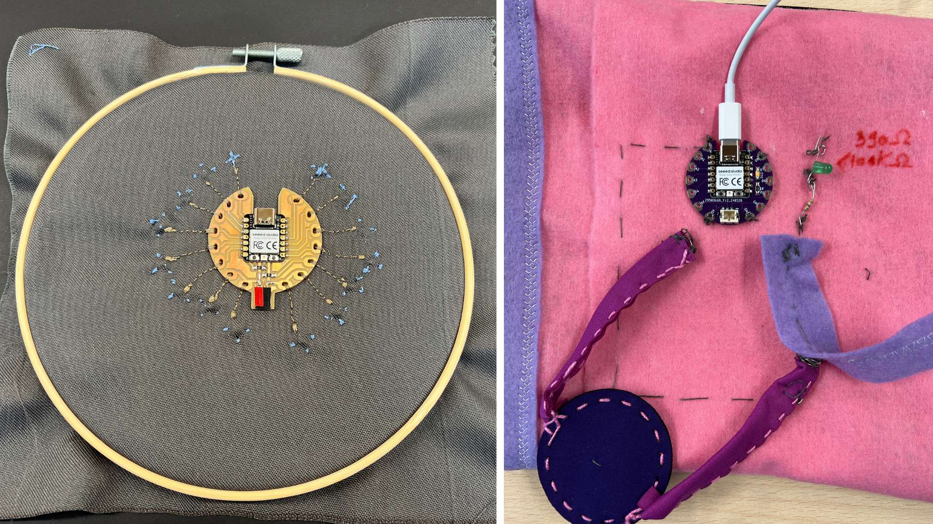
Finally, during 2024, at the end of June, I decided to redesign the board so that it could be manufactured in a PCB factory in order to be able to distribute it all over the world. At the Fab Lab León, the board was used during a mini Fabricademy together with friends from WeDo Fab Lab.
A very exciting moment for me was the presentation of the FabriXiao during FAB 24 in Puebla (Mexico) to the Fabricademy gurus, Anastasia Pistofidou and Claudia Simonelli, together with Nuria Robles (Cecilia Raspanti will be presented by Henk Buursen). ❤️

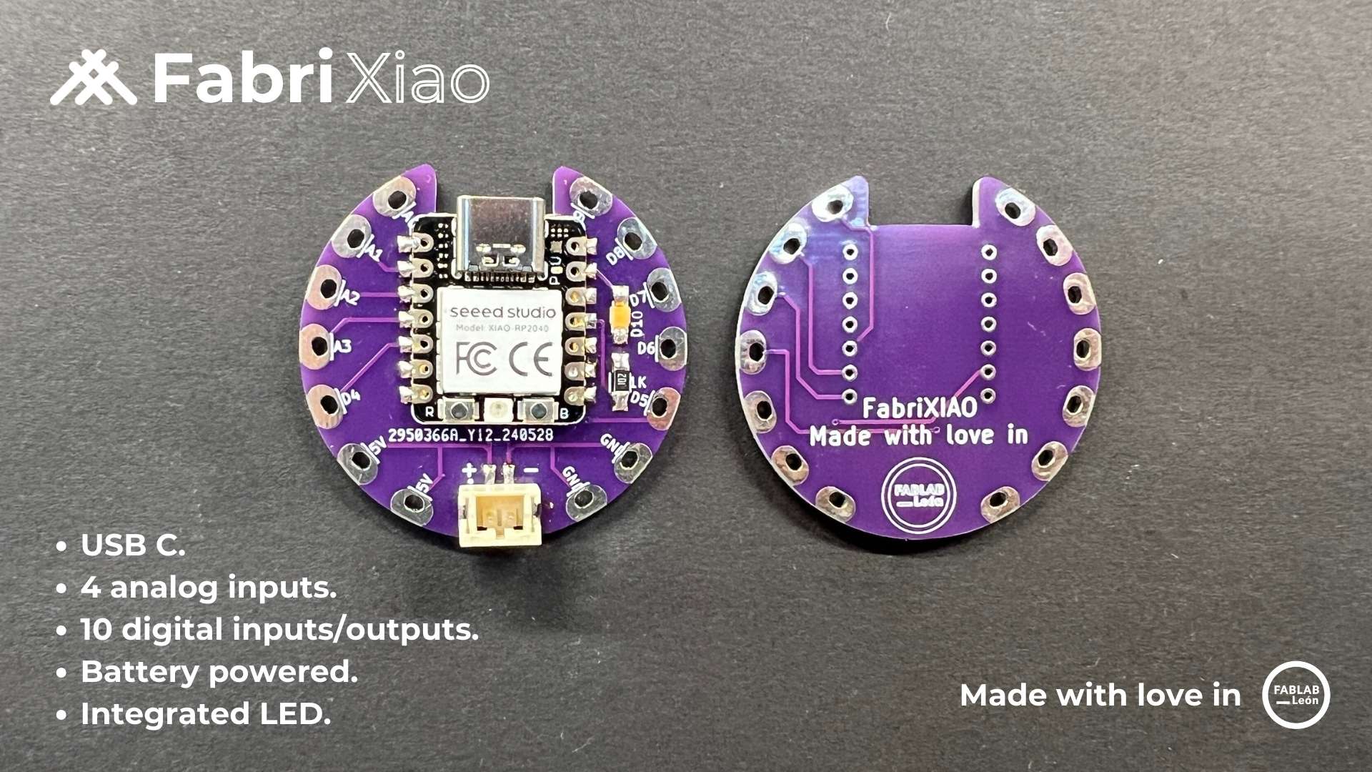
Features
- Small size: 40 mm.
- Programming via USB C.
- Two power connections and two GND connections.
- 4 analog inputs. 10 digital inputs/outputs.
- Connection via a 3.7 V battery.
- Includes an LED (D10) to test the board (assembly optional).
Datasheet Seeed Studio XIAO RP2040
Seeed Studio XIAO RP2040 is compatible with the Raspberry Pi RP2040 ecosystem as they share the same RP2040 chip. It supports multiple languages including C / MicroPython / CircuitPython. This will be a great tool for you to get started with MicroPython.
- Powerful MCU: Dual-core ARM Cortex M0+ processor, flexible clock running up to 133 MHz.
- Rich on-chip resources: 264KB of SRAM, and 2MB of on-board Flash memory
- Flexible compatibility: Support Micropython/Arduino/CircuitPython
- Easy project operation: Breadboard-friendly & SMD design, no components on the back
- Small size: As small as a thumb(20x17.5mm) for wearable devices and small projects.
- Multiple interfaces: 11 digital pins, 4 analog pins, 11 PWM Pins,1 I2C interface, 1 UART interface, 1 SPI interface, 1 SWD Bonding pad interface.
For general I/O pins: Working voltage of MCU is 3.3V. Voltage input connected to general I/O pins may cause chip damage if it' higher than 3.3V . For power supply pins: The built-in DC-DC converter circuit able to change 5V voltage into 3.3V allows to power the device with a 5V supply via VIN-PIN and 5V-PIN. Please pay attention to use, do not lift the shield cover.
After looking at the basic features, you will find the pinning of the XIAO RP2040. More information in this link. Here the Seeed Studio XIAO RP2040 pinout sheet.
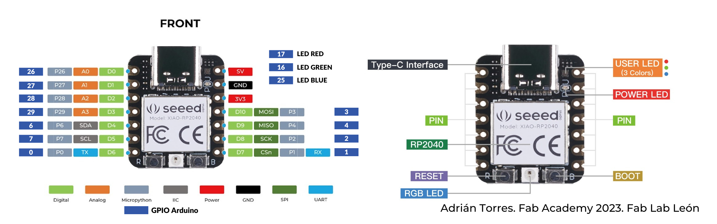
- 5V: Supply voltage 5V.
- GND: Ground.
- 3V3: Supply voltage 3V3.
- Digital pins (GPIO Pin number): 0, 1, 2, 3, 4, 6, 7, 26, 27, 28, 29
- Analog pins (GPIO Pin number): 26, 27, 28, 29
- LED Green (GPIO Pin number): 16
- LED Red (GPIO Pin number): 17
- LED Blue (GPIO Pin number): 25
- SDA (GPIO Pin number): 6
- SCL (GPIO Pin number): 7
- RGB LED_POWER (GPIO Pin number): 11
- RGB LED (GPIO Pin number): 12
Datasheet Seeed Studio XIAO ESP32-C3
Seeed Studio XIAO ESP32-C3 is an IoT mini development board based on the Espressif ESP32-C3 WiFi/Bluetooth dual-mode chip.
- Powerful CPU: ESP32-C3, 32 bit RISC-V single core processor that operates at up to 160 MHz
- Complete WiFi subsystem: Complies with IEEE 802.11b/g/n protocol and supports Station mode, SoftAP mode, SoftAP + Station mode, and promiscuous mode
- Bluetooth LE subsystem: Supports features of Bluetooth 5 and Bluetooth mesh
- Ultra-Low Power: Deep sleep power consumption is about 43μA
- Better RF performance: External RF antenna included
- Battery charging chip: Supports lithium battery charge and discharge management
- Rich on-chip resources: 400KB of SRAM, and 4MB of on-board flash memory
- Rich interfaces: 1xI2C, 1xSPI, 1xI2S, 2xUART, 11xGPIO(PWM), 4xADC, 1xJTAG bonding pad interface
For general I/O pins: This is 5v out from the USB port. You can also use this as a voltage input but you must have some sort of diode (schottky, signal, power) between your external power source and this pin with anode to battery, cathode to 5V pin. Working voltage of MCU is 3.3V.
After looking at the basic features, you will find the pinning of the XIAO ESP32-C3. More information in this link. Here the Seeed Studio XIAO ESP32-C3 pinout sheet.
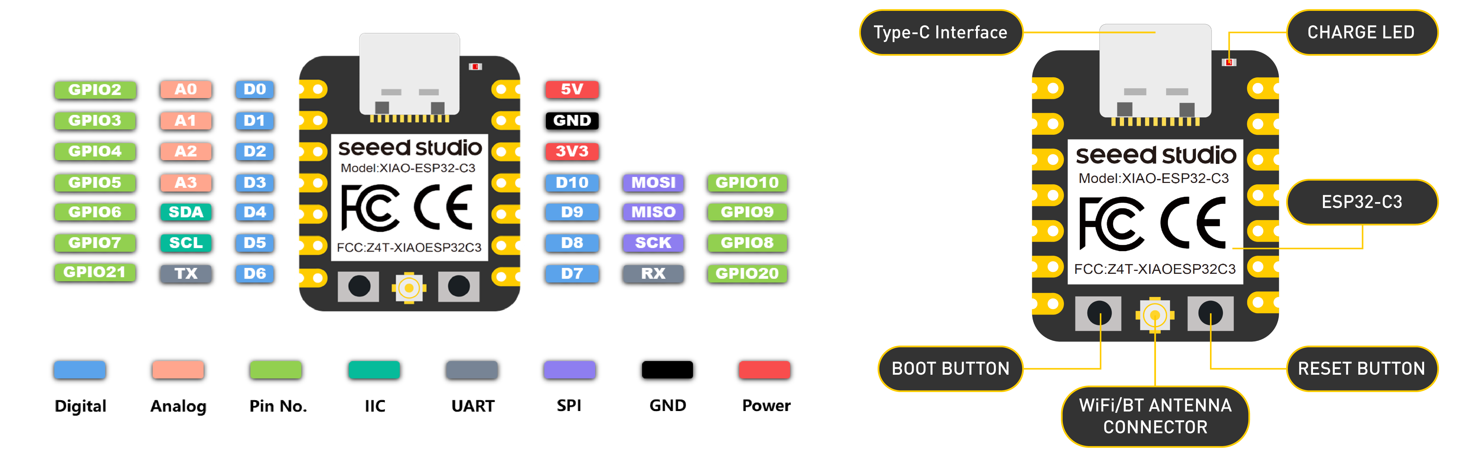
- 5V: Supply voltage 5V.
- GND: Ground.
- 3V3: Supply voltage 3V3.
- Digital pins (GPIO Pin number): D0, D1, D2, D3, D4, D5, D6, D7, D8, D9, D10, D11
- Analog pins (GPIO Pin number): A0, A1, A2, A3
- SDA (GPIO Pin number): D4
- SCL (GPIO Pin number): D5
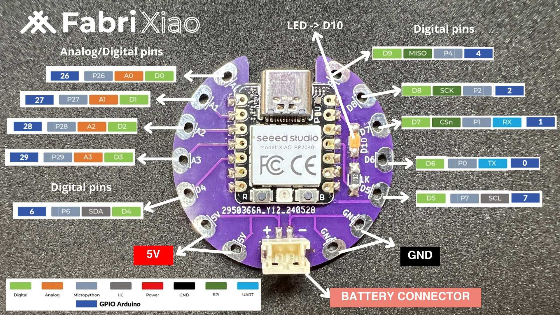
FabriXiao Pinout
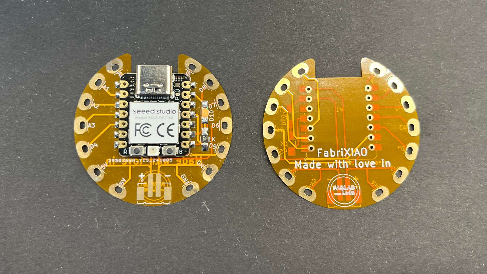
This is the pinout of the FabriXiao with the Seeed XIAO RP2040.
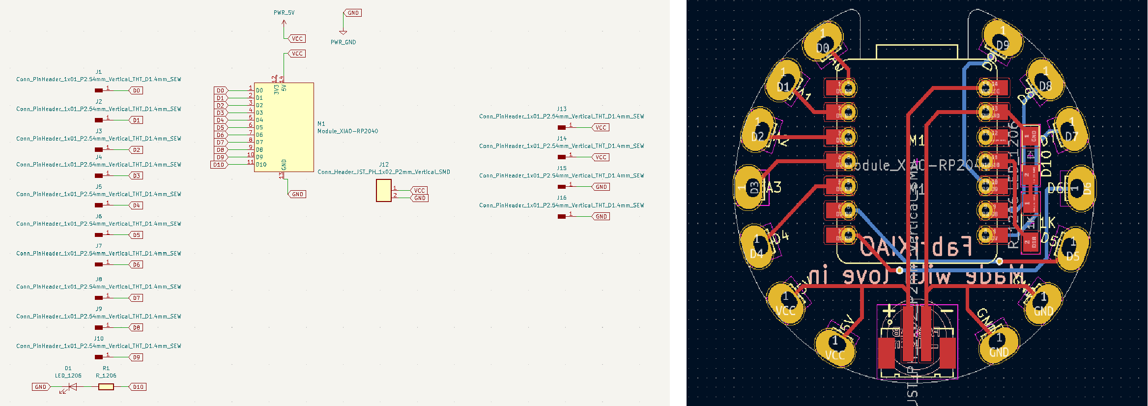
BOM and Schematic for FabriXiao
This is the schematic where you can see all the components.
Fabrixiao |
Where to buy? | Amount | Price | Total price |
| Seeed Studio XIAO RP2040 | Seeed Studio | 1 | 5,00 €/unit | 5,00 € |
| 1kΩ resistor | Digikey | 1 | 0,09 €/unit | 0,09 € |
| LED | Digikey | 1 | 0,35 €/unit | 0,35 € |
| Header JST PH 1x02 P2mm Vertical SMD | Digikey | 1 | 0,75 €/unit | 0,75 € |
| (Header JST PH 1x02 P2mm Horizontal SMD) optional ** | Digikey | 1 | 0,62 €/unit | 0,62 € |
| Total cost | 6,19 € |
**ATTENTION: If the Header JST PH 1x02 P2mm Horizontal SMD is used, you must use the FabriXiao Horizontal connector design.
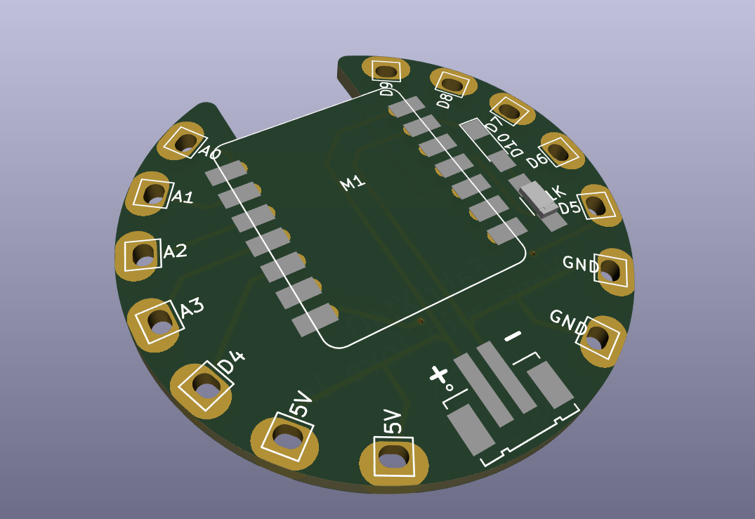
Board design
Here you can download the KICAD 6 files and the SVG's. You can also see a 3D simulation of the board. With the ZIP file you can go to JLCPCB or PCBWay and order your boards by uploading the file directly.
- FabriXiao Vertical connector
- FabriXiao Horizontal connector
- FabriXiao Vertical connector BOM
- FabriXiao Horizontal connector BOM
Flexible board
Manufacturer JLCPCB allows you to choose a flexible board from among the manufacturing options, for a very low price. This is the result.
Programming. Seeed Studio XIAO RP2040 with Arduino
- 1. We open the Arduino program.
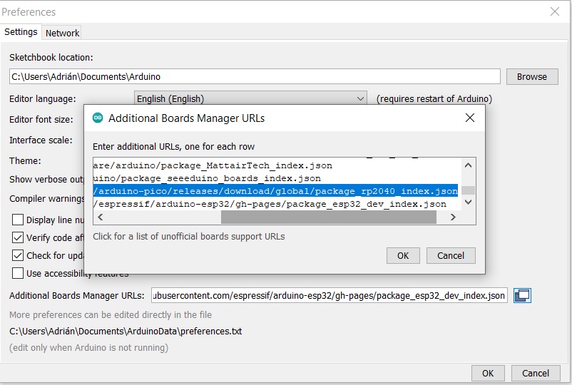
- 2. In Preferences, we will add the URL of the additional boards that you can find here. We need the Arduino-Pico by Earlephilhower
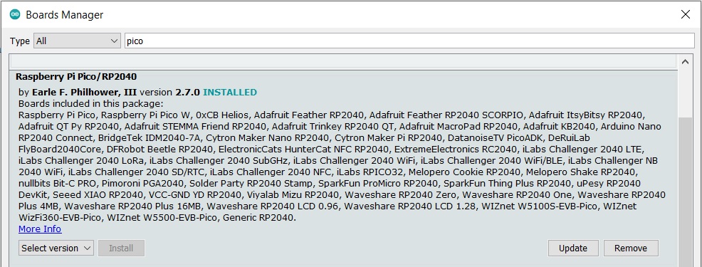
- 3. The next step is to download Pico in the boards manager.
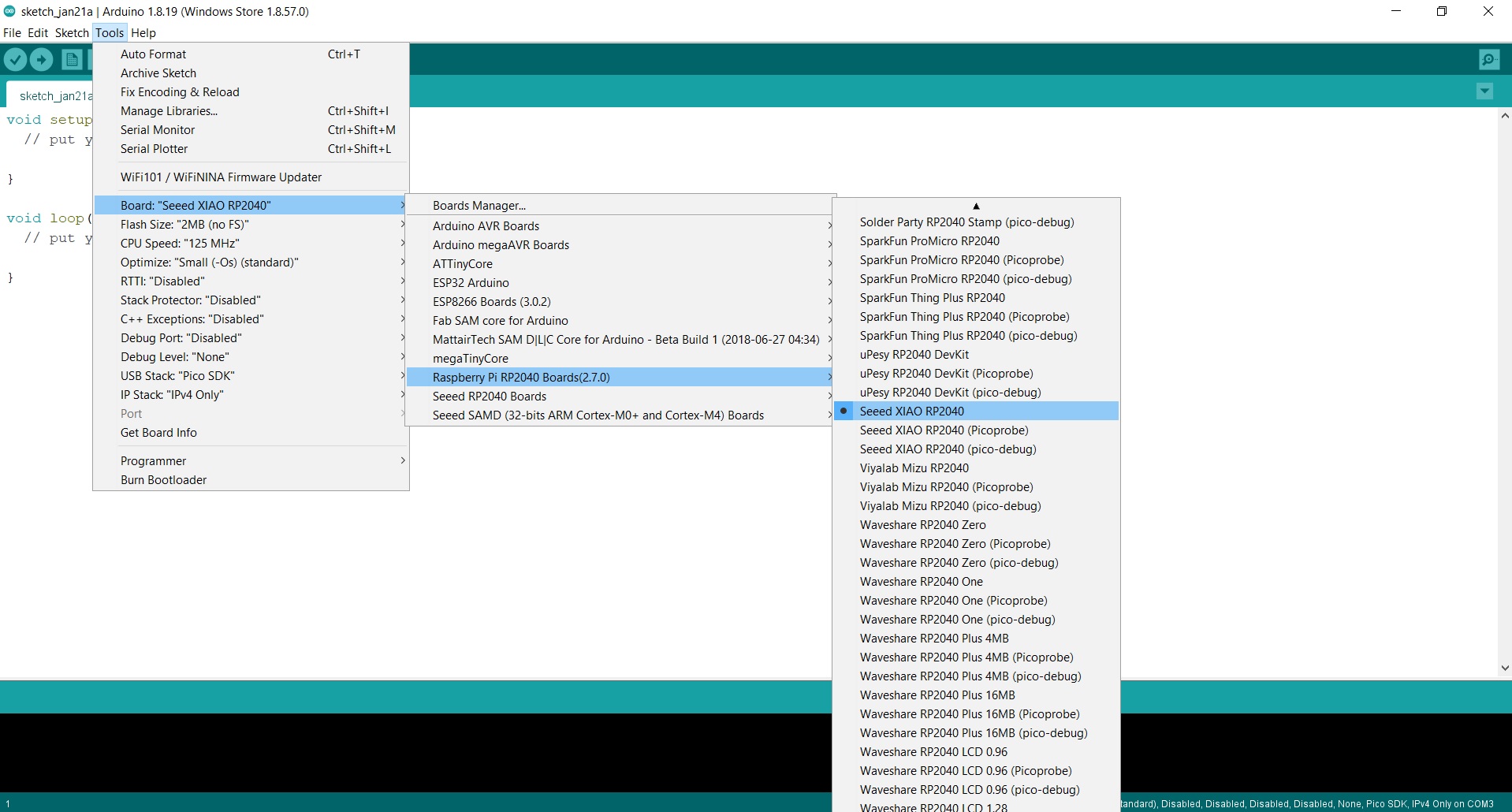
- 4. We configure the Arduino IDE for the Seeed Studio XIAO RP2040. The Seeed Studio XIAO RP2040 will appear in the COM port, in my case in COM 3.
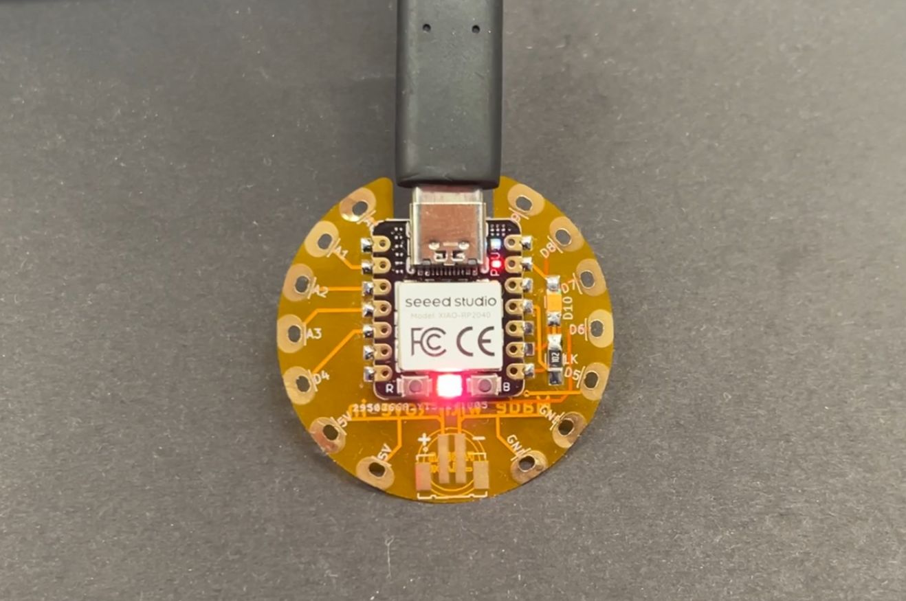
- 5. Now load the Blink program so that the LED on pin 3 (GPIO 10 or D10) blinks. When we upload it, all this information appears in the notifications section.
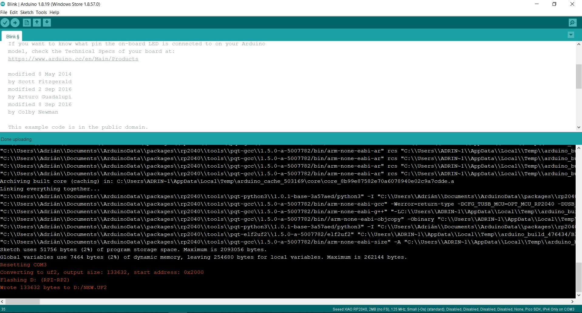
In this short video you can see the operation of a Blink on pin 3 (GPIO 10 OR D10) where the LED is integrated. 😍
Programming. Seeed Studio XIAO ESP32-C3 with Arduino
- 1. We open the Arduino program.
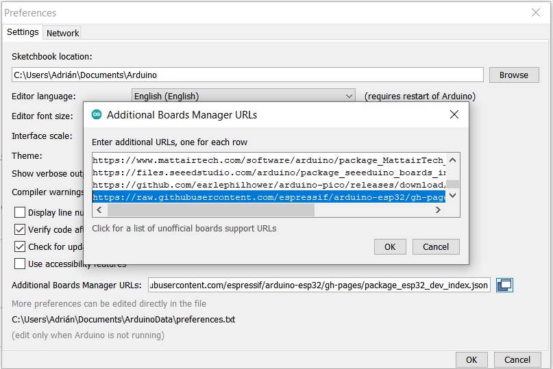
- 2. In Preferences, we will add the URL of the additional boards that you can find here. We need the Arduino ESP32 by Espressif
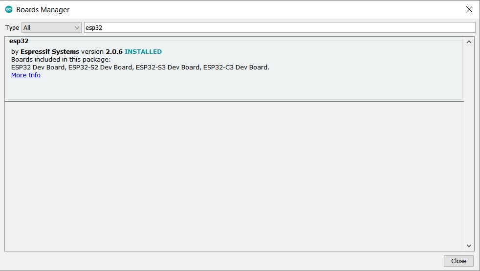
- 3. The next step is to download ESP32 in the boards manager.
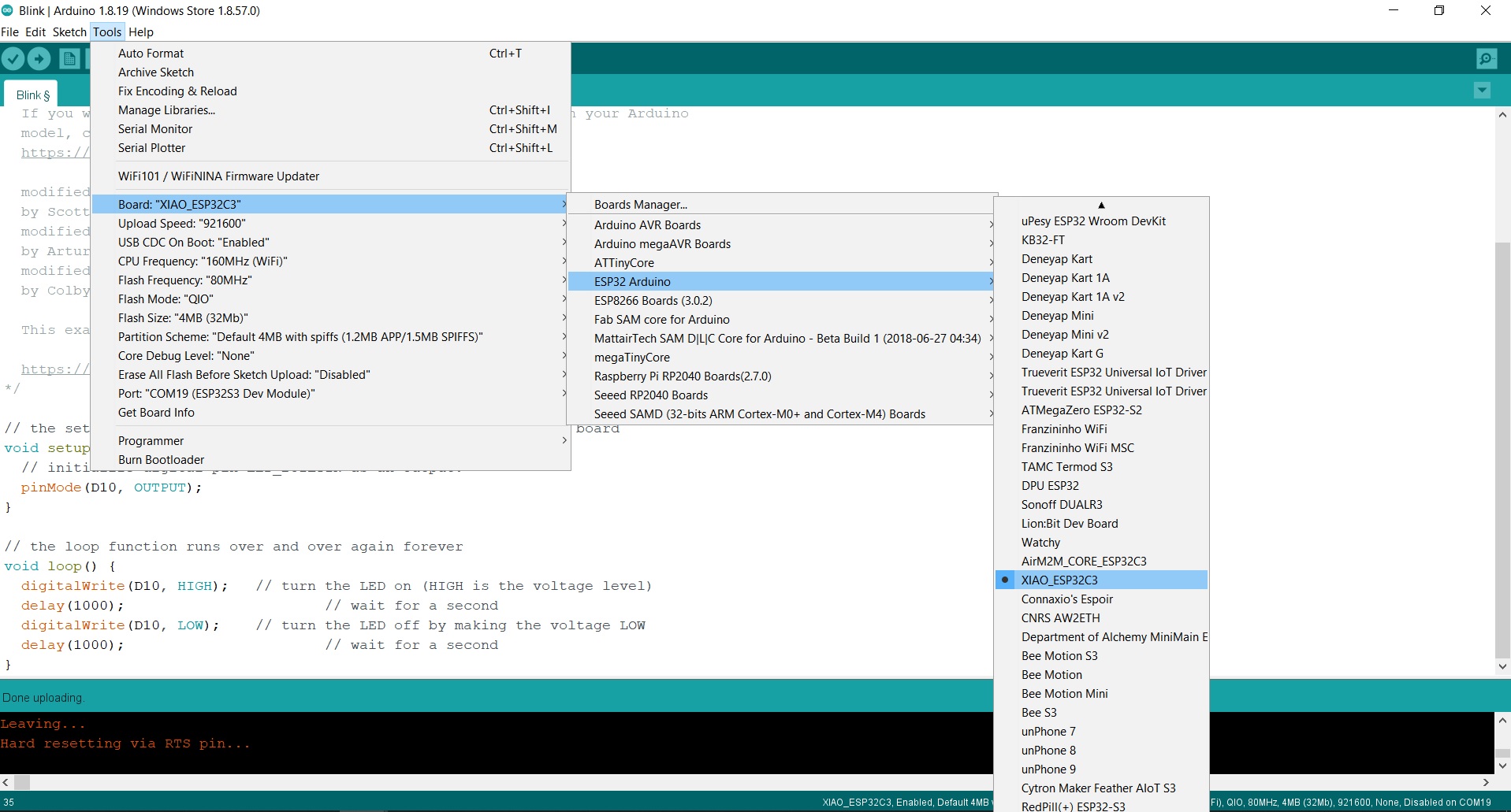
- 4. We configure the Arduino IDE for the Seeed Studio XIAO ESP32-C3. The Seeed Studio XIAO ESP32-C3 will appear in the COM port, in my case in COM 3.
- 5. Now load the Blink program so that the LED on pin 3 blinks. When we upload it, all this information appears in the notifications section.
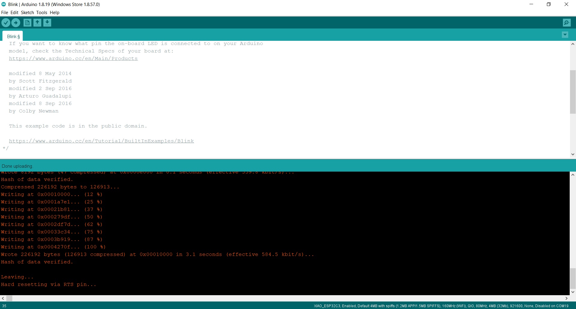
In this short video you can see the operation of a Blink on pin 3 where the LED is integrated. 😍
Inputs
Button
The button is the simplest element of the inputs. It is an open or closed contact that when we press it changes its state to closed or open.
In this case I have created a push button following Kobakant's documentation in the E-textiles class. I have connected the button to A0 (26) of the FabriXiao and to GND with cables with clamps. In the Arduino code I use the internal Pull-up resistor for the analog input. I also turn on the LED integrated in the FabriXiao on D10 (Arduino pin 3) with the button variation.
Here you will find the programming to use the button. Here you can find the Arduino file to download.
//Fab Academy 2024 - Fab Lab León
//Button
//FabriXiao
//XIAO RP2040
const int button_PIN= 26;
const int led_PIN = 3;
int value_button = 0;
void setup() {
// We assign the input and the output
pinMode(button_PIN, INPUT_PULLUP);
pinMode(led_PIN, OUTPUT);
}
void loop() {
// We read the value of the button
value_button = digitalRead(button_PIN);
// We turn the LED on or off as appropriate
if (value_button == LOW) {
digitalWrite(led_PIN, HIGH); // We turn on Led
}
else {
digitalWrite(led_PIN, LOW); // We turn off Led
}
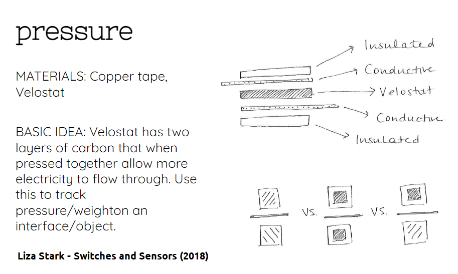
}Pressure sensor
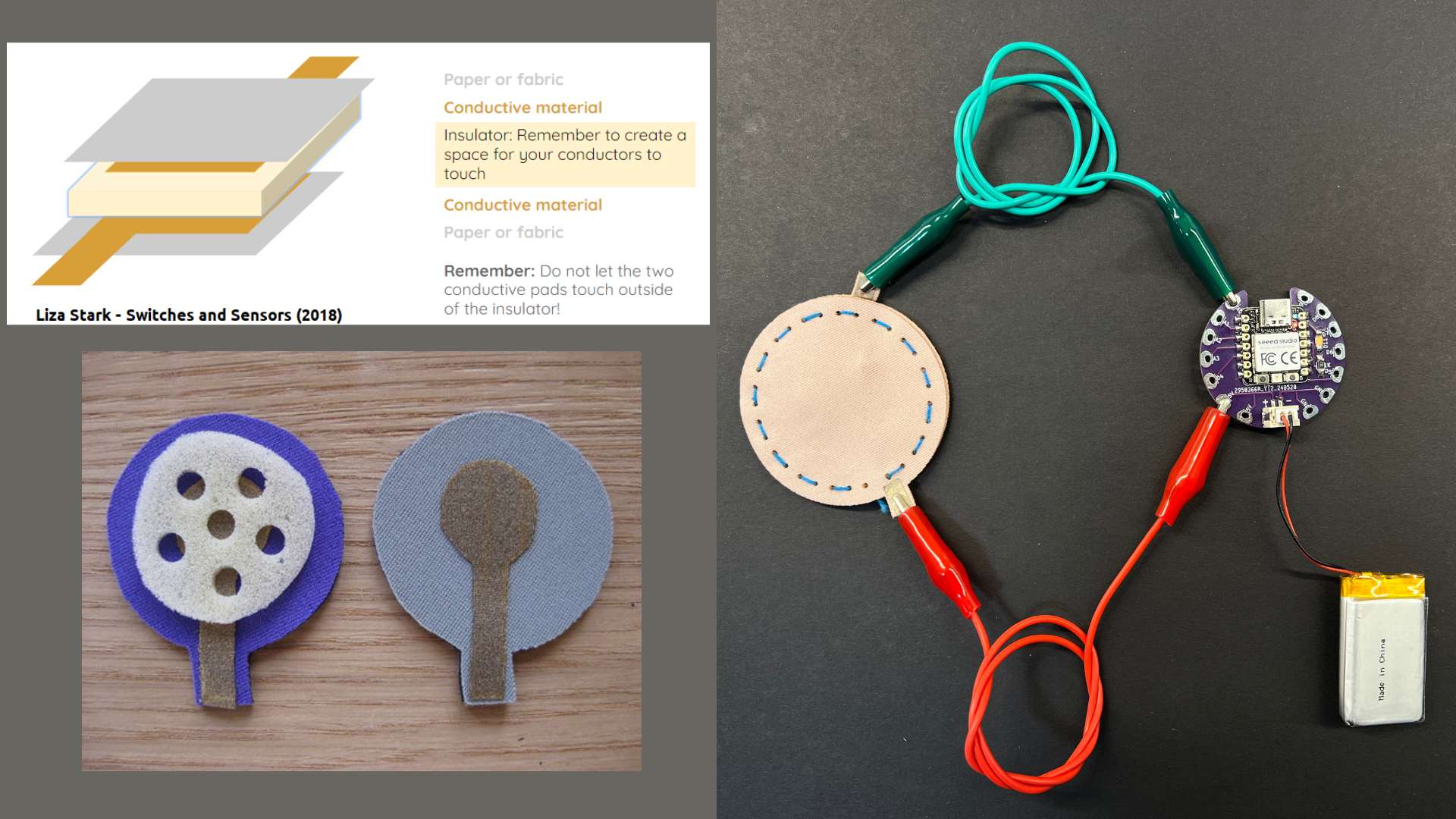
Thanks to the Fabricademy, in the E-Textiles class taught by Liza Stark and the knowledge of my instructor Nuria Robles I have created the sensor that I am going to connect to the FabriXiao.
To manufacture this sensor, we will need fabric, conductive tape or conductive wire and velostat.
- Velostat: Is a Carbon impregnated black polyethylene film material of about 4 thousand thick and Volume resistivity is <500 Ohms/cm. Conductivity is not affected by humidity or aging. Here you can find the datsheet.
- Conductive tape: This Conductive Nylon tape goes great with our other interesting materials, such as copper tape, ITO glass or plastic, conductive inks, etc. We found that the metallic nylon fabric has some great improvements over plain copper tape. You can find more information here or buy it at this link.
To create the textile flex sensor we can cut the fabric with the laser cutter, and help us when it comes to sewing. I leave you the following diagram of how the sensor will work and the layers that it is composed of. Scheme made by Liza Stark.
In this case I integrate the entire sensor into a frame where I will make the connections with conductive thread.
In this case I am going to use conductive thread. I connect 5V to one end of the sensor, the other side is connected to A0 (Arduino pin 26) and a 10K pull-down resistor connected to GND. I also turn on the LED integrated in the FabriXiao on D10 (Arduino pin 3) with the sensor variation.

Here you will find the programming to use a Pressure Sensor. Here you can find the Arduino file to download. Below you can see a video of how it works.
//Fab Academy 2024 - Fab Lab León
//Pressure Sensor
//FabriXiao
//XIAO RP2040
int sensorPin = A0;    // analog input pin to hook the sensor to A0 or 26
int sensorValue = 0;   // variable to store the value coming from the sensor
int ledPin = D10;      // LED connected to pin D10

void setup() {
  Serial.begin(115200); // initialize serial communications
  pinMode(ledPin, OUTPUT); // set the LED pin as an output
}

void loop() {
  sensorValue = analogRead(sensorPin); // read the value from the sensor
  sensorValue = map(sensorValue, 600, 1024, 0, 1024);
  Serial.println(sensorValue); // print value to Serial Monitor

  // Map the sensor value to a PWM range (0-255) for LED brightness
  int ledBrightness = map(sensorValue, 600, 1024, 0, 255);
  analogWrite(ledPin, ledBrightness); // set LED brightness

  delay(500); // short delay so we can actually see the numbers
}
Flexure Sensor.
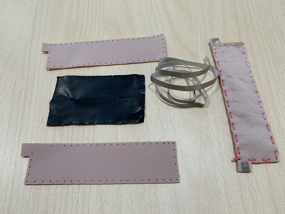
To manufacture this sensor, we will need fabric, conductive tape or conductive wire and velostat.
- Velostat: Is a Carbon impregnated black polyethylene film material of about 4 thousand thick and Volume resistivity is <500 Ohms/cm. Conductivity is not affected by humidity or aging. Here you can find the datsheet.
- Conductive tape: This Conductive Nylon tape goes great with our other interesting materials, such as copper tape, ITO glass or plastic, conductive inks, etc. We found that the metallic nylon fabric has some great improvements over plain copper tape. You can find more information here or buy it at this link.
To create the textile flex sensor we can cut the fabric with the laser cutter, and help us when it comes to sewing. I leave you the following diagram of how the sensor will work and the layers that it is composed of. Scheme made by Nuria Robles. 🥰
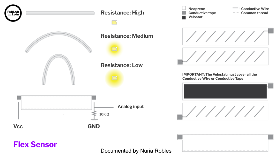
We will have this, two pieces of neoprene in this case, the velostat and the conductive tape. I will create inside a zig-zag pattern of conductive tape or conductive wire. Once I have the three parts, as if it were a "sandwich" one all putting the velostat in the middle.
In this case I am going to use three crocodile clips connected to some male pins. In this case by color the red wire will go to VCC, the black to GND and the yellow one that is signal to A0 (arduino pin 26). I also turn on the LED integrated in the FabriXiao on D10 (Arduino pin 3) with the sensor variation. IMPORTANT: We also need to connect a 10k pull-down resistor at the sensor signal output.
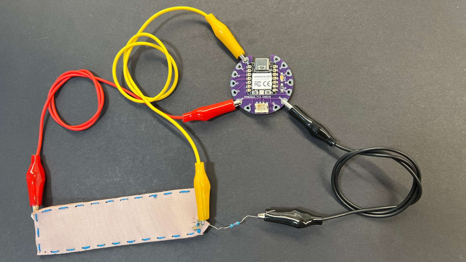
Here you will find the programming to use a Flexure Sensor. Here you can find the Arduino file to download. Below you can see a video of how it works.
//Fab Academy 2024 - Fab Lab León
//Textile Flexure Sensor
//FabriXiao
//XIAO RP2040
int sensorPin = A0;    // analog input pin to hook the sensor to A0 or 26
int sensorValue = 0;   // variable to store the value coming from the sensor
int ledPin = D10;      // LED connected to pin D10

void setup() {
  Serial.begin(115200); // initialize serial communications
  pinMode(ledPin, OUTPUT); // set the LED pin as an output
}

void loop() {
  sensorValue = analogRead(sensorPin); // read the value from the sensor
  sensorValue = map(sensorValue, 600, 1024, 0, 1024);
  Serial.println(sensorValue); // print value to Serial Monitor

  // Map the sensor value to a PWM range (0-255) for LED brightness
  int ledBrightness = map(sensorValue, 600, 1024, 0, 255);
  analogWrite(ledPin, ledBrightness); // set LED brightness

  delay(500); // short delay so we can actually see the numbers
}
Outputs
RGB LED
The RGB LED stands for Red, Blue and Green LEDs. RGB LED products combine these three colors to produce more than 16 million shades of light.
Inside the Seeed XIAO RP2040 it has an RGB LED incorporated, whose activation pins are 11 for Power and 12 for LED control.
Here you will find the programming to use a RGB LED. Here you can find the Arduino file to download. Below you can see a video of how it works.
//Fab Academy 2023 - Fab Lab León
//RGB LED
//Fab-Xiao
//original code from https://wiki.seeedstudio.com/XIAO-RP2040-with-Arduino/#rgb-led


#include

int Power = 11;
int PIN  = 12;
#define NUMPIXELS 1

Adafruit_NeoPixel pixels(NUMPIXELS, PIN, NEO_GRB + NEO_KHZ800);

void setup() {
  pixels.begin();
  pinMode(Power,OUTPUT);
  digitalWrite(Power, HIGH);

}

void loop() {
  pixels.clear();
  pixels.setPixelColor(0, pixels.Color(15, 25, 205));
  delay(400);
  pixels.show();
  pixels.clear();
  pixels.setPixelColor(0, pixels.Color(103, 25, 205));
  delay(400);
  pixels.show();
  pixels.clear();
  pixels.setPixelColor(0, pixels.Color(233, 242, 205));
  delay(400);
  pixels.show();
  pixels.clear();
  pixels.setPixelColor(0, pixels.Color(233, 23, 23));
  delay(400);
  pixels.show();
  pixels.clear();
  pixels.setPixelColor(0, pixels.Color(12, 66, 101));
  delay(400);
  pixels.show();
  delay(500);

}
ESP 32 + Web Server + LED
One of the features of the XIAO ESP32-C3 is that it can be connected via Bluetooth or Wifi. In this project you’ll create a standalone web server with an ESP32 that controls output (one LED) using the Arduino IDE programming environment. The web server is mobile responsive and can be accessed with any device that as a browser on the local network. We’ll show you how to create the web server and how the code works step-by-step. You can find more info here
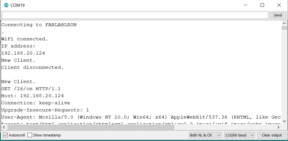
Here you will find the programming to use a Web Server with a LED. Here you can find the Arduino file to download. Below you can see a video of how it works.
When you have uploaded the code, you should open the Serial Monitor to see the IP address that you will have to copy to paste into a browser.
Files
Find below the files that I made for this project.