
Week 12. Interface and Application Programming
Like the previous week, there are two types of assignments, one group and one individual. In my case being alone in the Fab Lab, I do both.
- Write an application that interfaces a user with an input and/or output device that you made. ✔
- Compare as many tool options as possible. ✔
- Linked to the group assignment page. ✔
- Documented your process. ✔
- Explained the UI that you made and how you did it. ✔
- Outlined problems and how you fixed them. ✔
- Included original code (or a screenshot of the app code if that's not possible). ✔
- Included a ‘hero shot/video’ of your application running with your board. ✔
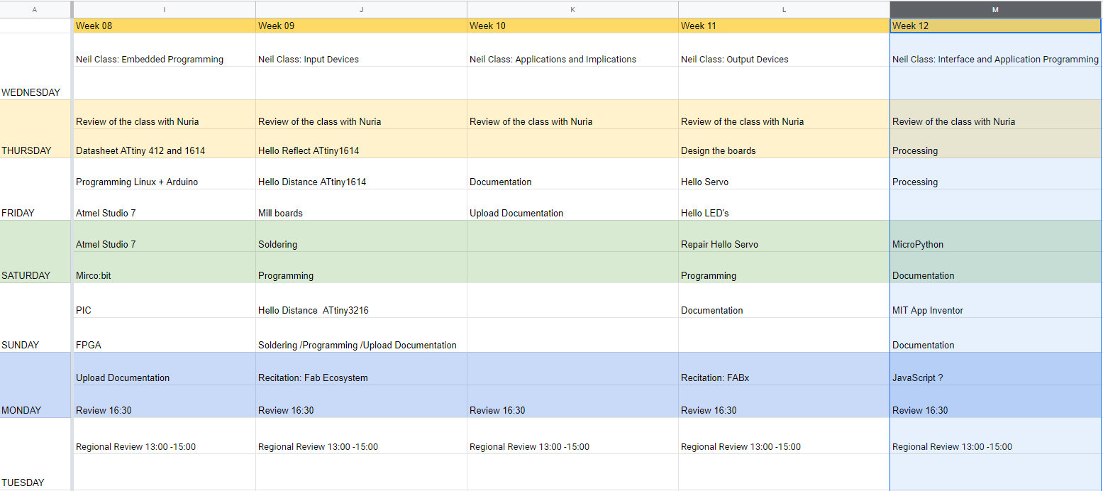
Like every week, my weekly schedule. 😊
This week I am going to use Processing and create various programs with the sensors I used in Input Devices week. Later I also want to use Micropython, the MIT App Inventor application or Node.js that Neil commented. Being confined at home I can have more time to investigate. Wish me luck. 😊
Group Assignment
The Group Assignment page is at the following link.
If you click on this link, you go to the Group Assignment section that I have done for this week.
Processing
3 years ago I attended a workshop at the Fundación Cerezales Antonio y Cinia taught by Alfredo Calosci where I discovered Processing.
Last year my friend Marta Verde gave us an online class on basic processing concepts. Thanks Marta.😘 Processing has a very similar environment to the Arduino IDE and very nice things can be done.
Processing + Hello Distance Time of Fligth. VL53L0X
The first thing we must do to obtain data from a sensor is to program it to send us the data through the Serial Port. In this case I only need numbers, values between 0 and 1024. To do this I load to the ATtiny1614 using UPDI the following Arduino program in Linux.
Important: Remember to set the speed to 115200 baud (in the Input Devices week I set the speed to 9600 baud and nothing came out).
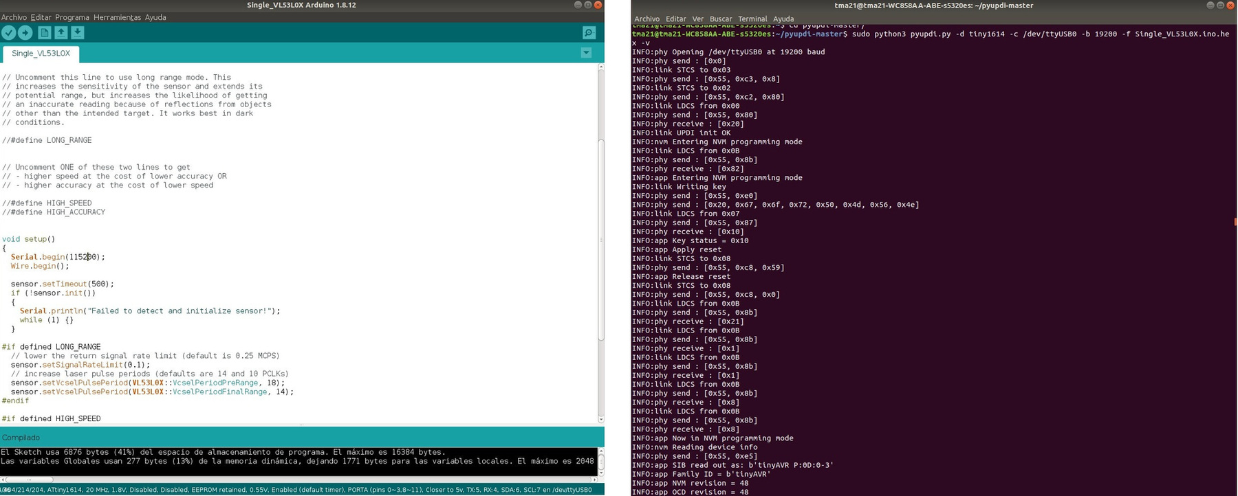
Once the program is loaded and I verify that from the terminal using the Pyserial I have values I pass to Processing. I have it installed in Windows and I use version 3.5.3.
Processing programming uses C language. For reference I use the following Make book: Getting Started with Processing and the Open Lab Cheat Sheet.
As in the Arduino IDE the first thing we do is declare some Variables and Libraries (It is important to use the processing.serial library) then we have the Void Setup where we define the work area (runs only once) and finally the Void Draw where we draw the elements that we are going to use the processes (runs repeatedly during the execution).
I am going to describe the basic commands that I am going to use in this program:
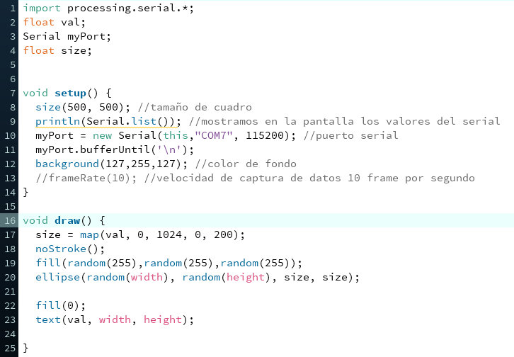
In this example I draw random spheres, variable in size by the distance sensor and random colors. As Marta Verde says, random is also beautiful.😍
Finally, the following instructions for serial communication between our board and Processing must be added at the end of the sketch.
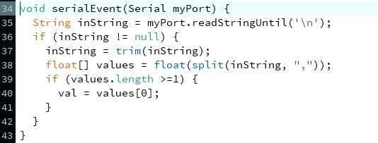
And this is the result of spheres of different sizes and colors depending on the distance of the VL53L0X sensor.
//Adrián Torres
//Fab Academy 2020
//Fab Lab León
import processing.serial.*;
float val;
Serial myPort;
float size;


void setup() {
  size(500, 500); //tamaño de cuadro
  println(Serial.list()); //mostramos en la pantalla los valores del serial
  myPort = new Serial(this,"COM7", 115200); //puerto serial
  myPort.bufferUntil('\n');
  background(127,255,127); //color de fondo
  //frameRate(10); //velocidad de captura de datos 10 frame por segundo
}

void draw() {
  size = map(val, 0, 1024, 0, 200); //tamaño mapeado.
  noStroke();
  fill(random(255),random(255),random(255)); //relleno de las esferas random
  ellipse(random(width), random(height), size, size); //lugar y tamaño de la esfera

  fill(0); //color del texto
  text(val, width, height); // valor de la medida

}

void serialEvent(Serial myPort) {
  String inString = myPort.readStringUntil('\n');
  if (inString != null) {
    inString = trim(inString);
    float[] values = float(split(inString, ","));
    if (values.length >=1) {
      val = values[0];
    }
  }
}
Processing + Hello Reflect: Image Rotation.
Like the previous test, the first thing to do is upload a program to the ATtiny1614 of the Hello Reflect so that it can obtain the measurement data by Serial. To do this I load to the ATtiny1614 using UPDI the following Arduino program in Linux. Important: Remember to set the speed to 115200 baud.
In this example I use an image and want to rotate it. Important we must save the image in the Processing or project folder that we are using and in .png format.
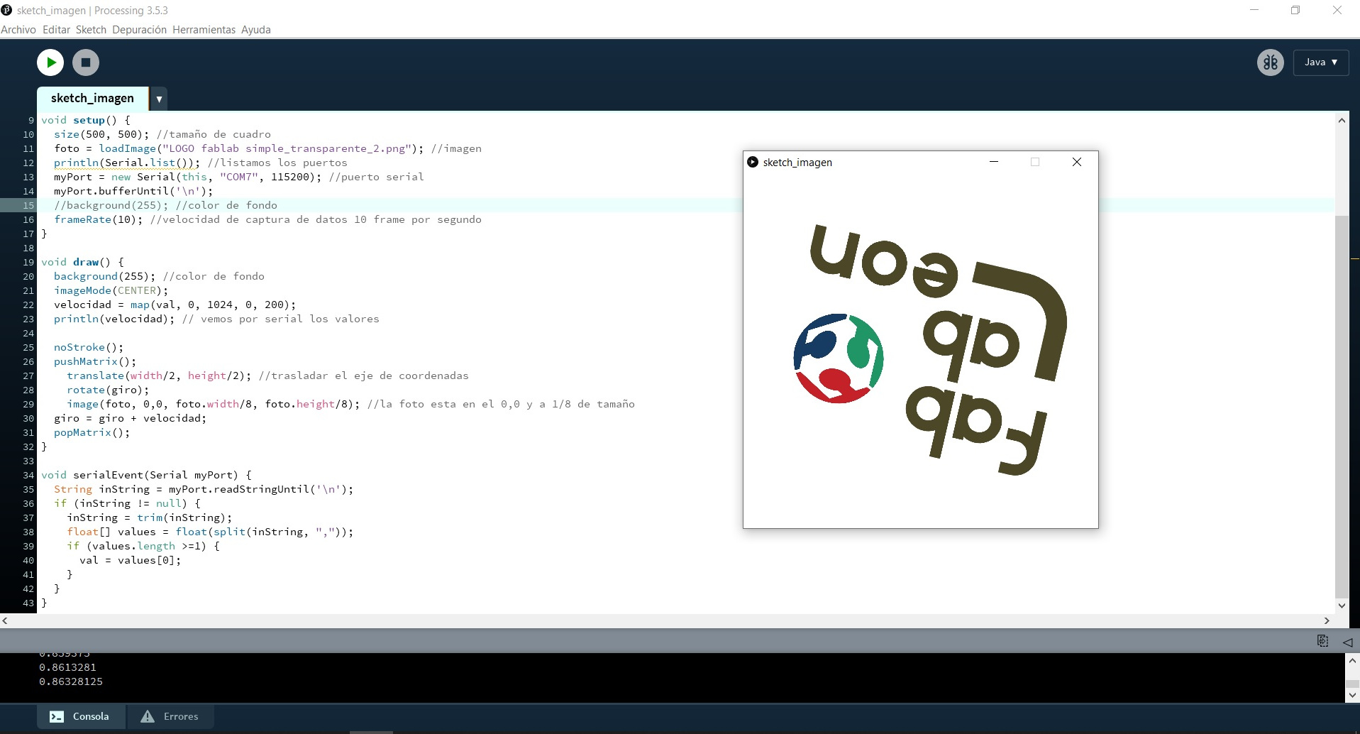
The first test of the code, the image remained as a sweep. This is the video.
If within the Void Draw loop I tell you that I want the Background to be white, I can make the image rotate and the previous image does not remain as a background.
And this is the code to rotate an image by varying its speed with the input of the Phototransistor.
//Adrián Torres
//Fab Academy 2020
//Fab Lab León


PImage foto;
import processing.serial.*;
float val;
Serial myPort;
float giro;
float velocidad;


void setup() {
  size(500, 500); //tamaño de cuadro
  foto = loadImage("LOGO fablab simple_transparente_2.png"); //imagen
  println(Serial.list()); //listamos los puertos
  myPort = new Serial(this, "COM7", 115200); //puerto serial
  myPort.bufferUntil('\n');
  //background(255); //color de fondo
  frameRate(10); //velocidad de captura de datos 10 frame por segundo
}

void draw() {
  background(255); //color de fondo
  imageMode(CENTER);
  velocidad = map(val, 0, 1024, 0, 200);
  println(velocidad); // vemos por serial los valores

  noStroke();
  pushMatrix();
    translate(width/2, height/2); //trasladar el eje de coordenadas
    rotate(giro);
    image(foto, 0,0, foto.width/8, foto.height/8); //la foto esta en el 0,0 y a 1/8 de tamaño
  giro = giro + velocidad;
  popMatrix();
}

void serialEvent(Serial myPort) {
  String inString = myPort.readStringUntil('\n');
  if (inString != null) {
    inString = trim(inString);
    float[] values = float(split(inString, ","));
    if (values.length >=1) {
      val = values[0];
    }
  }
}
Processing + Hello Reflect: Level Crossing Barrier.
I wanted to test how I could make an interface about my project. To do this using the Phototransistor of the Hello Reflect when it detects movement, the barrier rises or falls.
Within Processing there is a menu where you can create the colors and it offers you the value in RGB code. So I designed the base of the barrier in gray and the barrier in red.
Within Processing there is the option of pushMatrix () and popMatrix () to make an object have a different coordinate axis than the general one or if we want to rotate it. The first test I make is an error because it rotates on the continuous basis.
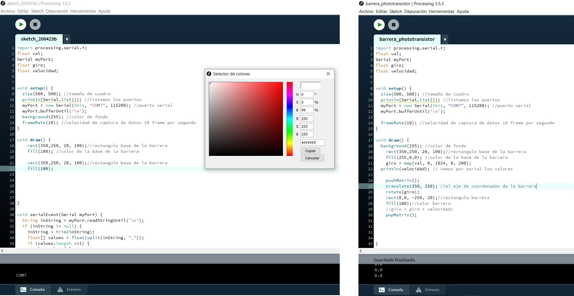
The problem was that he was using the data variable to add it to the turn and speed, so it was a continuous turn. I change the variable so that it only comes out in the turn and I get a movement of about 70º.
Here is the code for the movement of the barrier.
//Adrián Torres
//Fab Academy 2020
//Fab Lab León


import processing.serial.*;
float val;
Serial myPort;
float giro;
float velocidad;


void setup() {
  size(500, 500); //tamaño de cuadro
  println(Serial.list()); //listamos los puertos
  myPort = new Serial(this, "COM7", 115200); //puerto serial
  myPort.bufferUntil('\n');

  frameRate(10); //velocidad de captura de datos 10 frame por segundo
}

void draw() {
  background(255); //color de fondo
    rect(350,250, 20, 100);//rectangulo base de la barrera
    fill(255,0,0); //color de la base de la barrera
    giro = map(val, 0, 1024, 0, 200);
  println(velocidad); // vemos por serial los valores

    pushMatrix();
    translate(350, 250); //el eje de coordenadas de la barrera
    rotate(giro);
    rect(0,0, -250, 20);//rectangulo barrera
    fill(180);//color barrera
    //giro = giro + velocidad;
    popMatrix();
}

void serialEvent(Serial myPort) {
  String inString = myPort.readStringUntil('\n');
  if (inString != null) {
    inString = trim(inString);
    float[] values = float(split(inString, ","));
    if (values.length >=1) {
      val = values[0];
    }
  }
}
Here is the files to download.
- Arduino Program Hello Distance
- Processing Random Colours
- Arduino Program Hello Reflect
- Processing Image Rotation
- Processing Level Crossing Barrier
Group Assignment
This is our group page where we upload the Group Assignment.
MicroPython + ESP32
MicroPython Configuration
Python is the most widely used programming language and MicroPython was created for digital electronics. It is a widely used language to program new microcontrollers that contain WIFI, such as ESP32 or ESP8266.

In my case I have not used Python, except for some application that uses it. So searching the Internet I found the following page where there are several tutorials to discover MicroPython. You accompany me? 😉
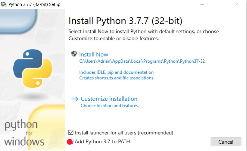
The first thing we need is to install the Toolchain called that we are going to use to program the ESP32. In this case it is uPyCraft IDE. The first thing we need is to install Python and a stable version as Neil told us in class. In this case I download version 3.7.7.
Once Python 3.7.7 is downloaded, we run it, in the next window we create the PATH.
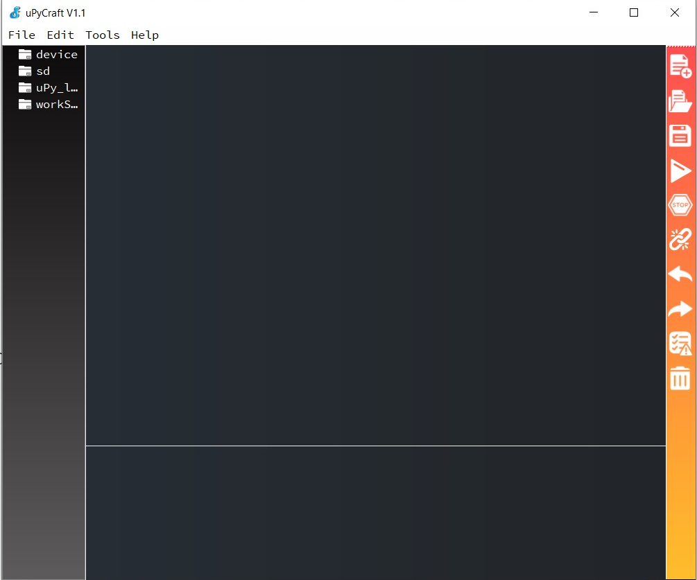
Once Python is installed, we will download the uPyCraft IDE. In my case I am using Windows, this is its version.
We execute the .exe file and this will be the appearance of the uPyCraft IDE.
Once we have installed the toolchain that we are going to use to communicate and program the board, we need to flash the ESP32 with the Firmware so that we can program it with MicroPython.
In my case the board model that I am going to use is an ESP32. Within the following link are several firmwares, but like I did with Python, I download a stable version. Firmware with ESP-IDF v3.x: esp32-idf3-20200422-v1.12-388-g388d419ba.bin
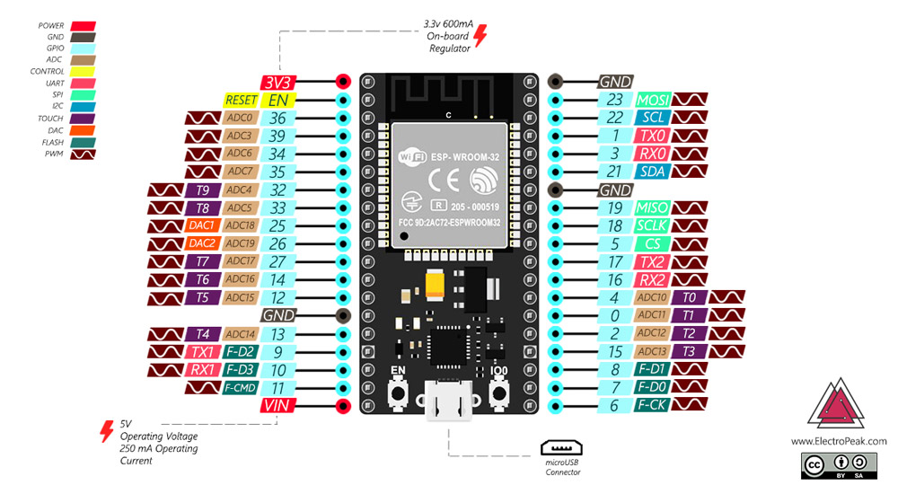
This is the pinout and the components that the ESP32 has.
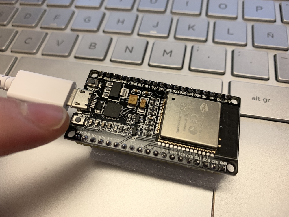
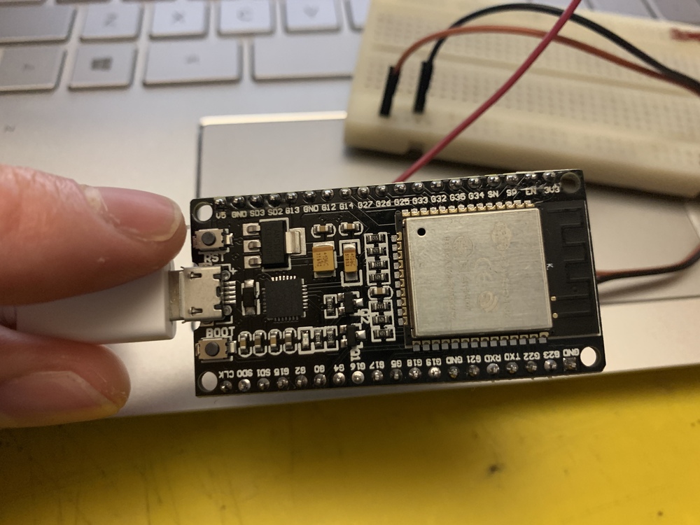
Once the Firmware is downloaded, we will Flash the ESP32. For this we open the uPyCraft IDE, connect the ESP32 to the computer and it must recognize us. If not, we install the Drivers for the CP2102 chip. If the connection continues to fail, we are using a power cable and not a data cable. It is also recommended to restart the computer, it happened to me. 😅
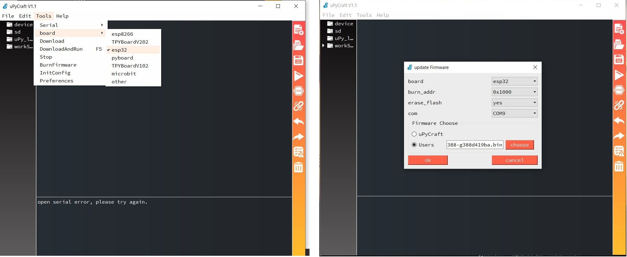
Once the ESP32 computer has recognized us, we will load the firmware through the Tools menu, where we will choose the board. In this case an ESP32, on the COM9 port, burn adress 0x1000, was flash: yes and we chose the firmware that we have downloaded. This is important burn adress 0x1000, because I had it in the value 0x0 and it doesn't work. 😬
When we have it ready, press the BOOT button and at the same time press OK to load the Firmware.
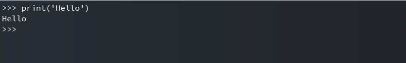
To find out if we have a connection to the board and if it has successfully loaded the firmware, we can write the command print ('Hello') in the terminal and it will reply with a Hello. Cool 🤩.
The next thing to do is create two files called boot.py and main.py . These files do the following:
- boot.py: runs when the device starts and sets up several configuration options;
- main.py: this is the main script that contains your code. It is executed immediately after the boot.py.
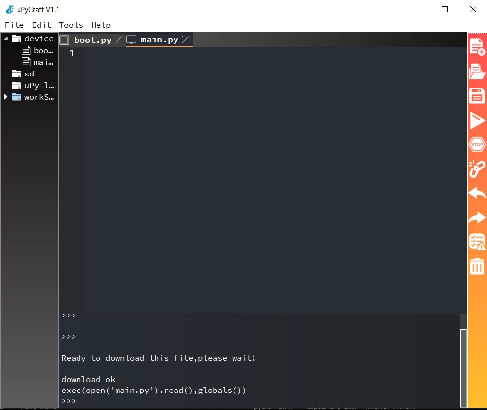
Once the two files are created, we save them and click the Download and run button to upload the file to your ESP board. The following information will appear in the terminal. We are now ready to start a program. We should do this whenever we start a new program.
ESP32 MicroPython Web Server – Control Outputs
Now it's time to do the first program, in this case from a Web Server press a button and turn on the ESP32 LED. For this I use the following code on this page.
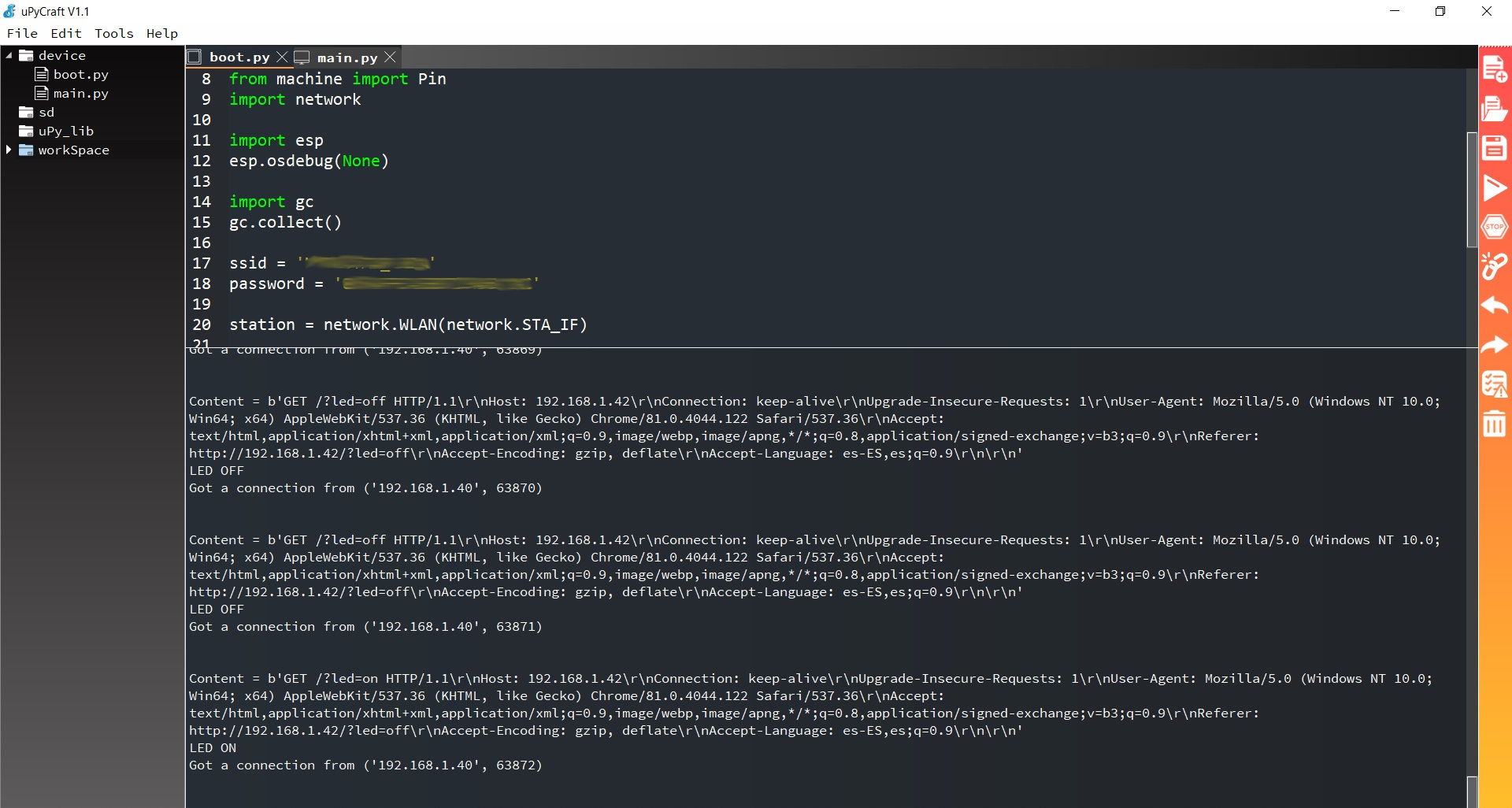
boot.py
# boot.py
# Adrián Torres - Fab Academy 2020 - Fab Lab León
# Complete project details at https://RandomNerdTutorials.com

try:
  import usocket as socket
except:
  import socket    # create our web server using sockets and the Python socket API.

from machine import Pin
import network

import esp
esp.osdebug(None)

import gc
gc.collect()

ssid = 'REPLACE_WITH_YOUR_SSID'    #  the name of our WIFI
password = 'REPLACE_WITH_YOUR_PASSWORD' #  the password of our WIFI

station = network.WLAN(network.STA_IF)

station.active(True)
station.connect(ssid, password)

while station.isconnected() == False:
  pass

print('Connection successful')
print(station.ifconfig())

led = Pin(2, Pin.OUT)  # the LED output pin.
And now the next code for the main.py I have to put the code like this because the HTML of the program and that of my page collide. 😪
main.py
# Complete project details at https://RandomNerdTutorials.com

def web_page():
  if led.value() == 1:  # LED value
    gpio_state="ON"
  else:
    gpio_state="OFF"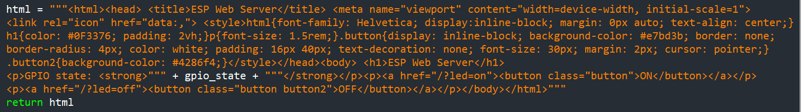
s = socket.socket(socket.AF_INET, socket.SOCK_STREAM)
s.bind(('', 80))
s.listen(5)
while True:
conn, addr = s.accept()
print('Got a connection from %s' % str(addr))
request = conn.recv(1024)
request = str(request)
print('Content = %s' % request)
led_on = request.find('/?led=on')
led_off = request.find('/?led=off')
if led_on == 6:
print('LED ON')
led.value(1)
if led_off == 6:
print('LED OFF')
led.value(0)
response = web_page()
conn.send('HTTP/1.1 200 OK\n')
conn.send('Content-Type: text/html\n')
conn.send('Connection: close\n\n')
conn.sendall(response)
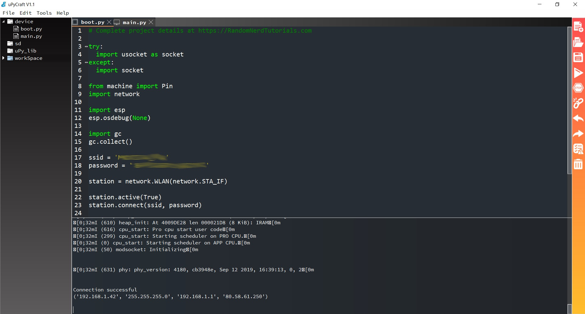
conn.close()Once we have the two files, we save them. Now we are going to load them to ESP32, for this click on the DownloadAndRun button. After uploading the files, press the ESP EN/RST on-board button.
Sometimes it gives us a little error, and it tells us Reflushing trees; it is solved pressing in the menu doing Reflush Directory. Once ESP32 has been connected, the terminal will send us the IP address where we will connect to see the Web. In my case it is 192.168.1.42
This is the result of the program if I put the IP on my computer and press the buttons change the state of the LED.
From the terminal to see what each instruction we press on the screen does, from which IP it comes, the state of the LED ... Curious. 😎
ESP32 MicroPython with DHT11 Web Server
The following program tries to send the DHT11 sensor data (temperature and humidity) through a Web Server. I have followed the next tutorial.
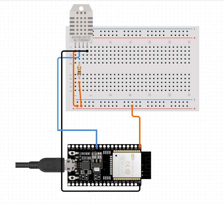
The schematic is as follows, designed with Circuito.io. ESP32, 10K resistor, DTH11 sensor and cables are required. The DTH11 signal output is connected to GPIO 14 of ESP32.
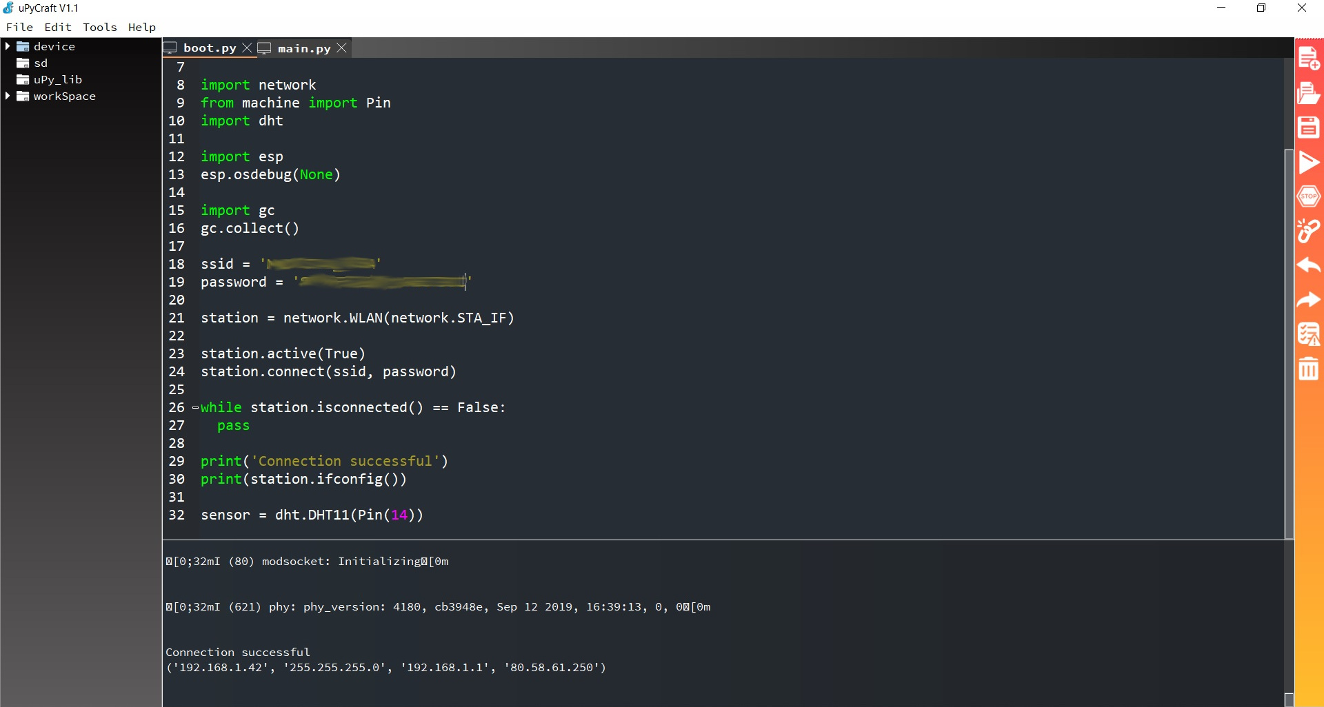
As I explain in the configuration of the uPyCraft IDE we must create two files, boot.py and main.py. The first thing, as before, is to create the boot.py file.
boot.py
# boot.py
# Adrián Torres - Fab Academy 2020 - Fab Lab León
# Complete project details at https://RandomNerdTutorials.com

try:
  import usocket as socket
except:
  import socket  # create our web server using sockets and the Python socket API.

import network
from machine import Pin
import dht

import esp
esp.osdebug(None)

import gc
gc.collect()

ssid = 'REPLACE_WITH_YOUR_SSID'    #  the name of our WIFI
password = 'REPLACE_WITH_YOUR_PASSWORD'    #  the password of our WIFI

station = network.WLAN(network.STA_IF)

station.active(True)
station.connect(ssid, password)

while station.isconnected() == False:
  pass

print('Connection successful')
print(station.ifconfig())

sensor = dht.DHT11(Pin(14))   # DHT11 sensor connection pin
And now the next code for the main.py I have to put the code like this because the HTML of the program and that of my page collide. 😪 With the following web page of icons I modify the HTML and put other logos and change the text.
main.py
# main.py
# Adrián Torres - Fab Academy 2020 - Fab Lab León
# Complete project details at https://RandomNerdTutorials.com

def read_sensor():     # reads temperature and humidity
  global temp, hum
  temp = hum = 0
  try:
    sensor.measure()
    temp = sensor.temperature()
    hum = sensor.humidity()
    if (isinstance(temp, float) and isinstance(hum, float)) or (isinstance(temp, int) and isinstance(hum, int)):
      msg = (b'{0:3.1f},{1:3.1f}'.format(temp, hum))

      # uncomment for Fahrenheit
      #temp = temp * (9/5) + 32.0

      hum = round(hum, 2)
      return(msg)
    else:
      return('Invalid sensor readings.')
  except OSError as e:
return('Failed to read sensor.') 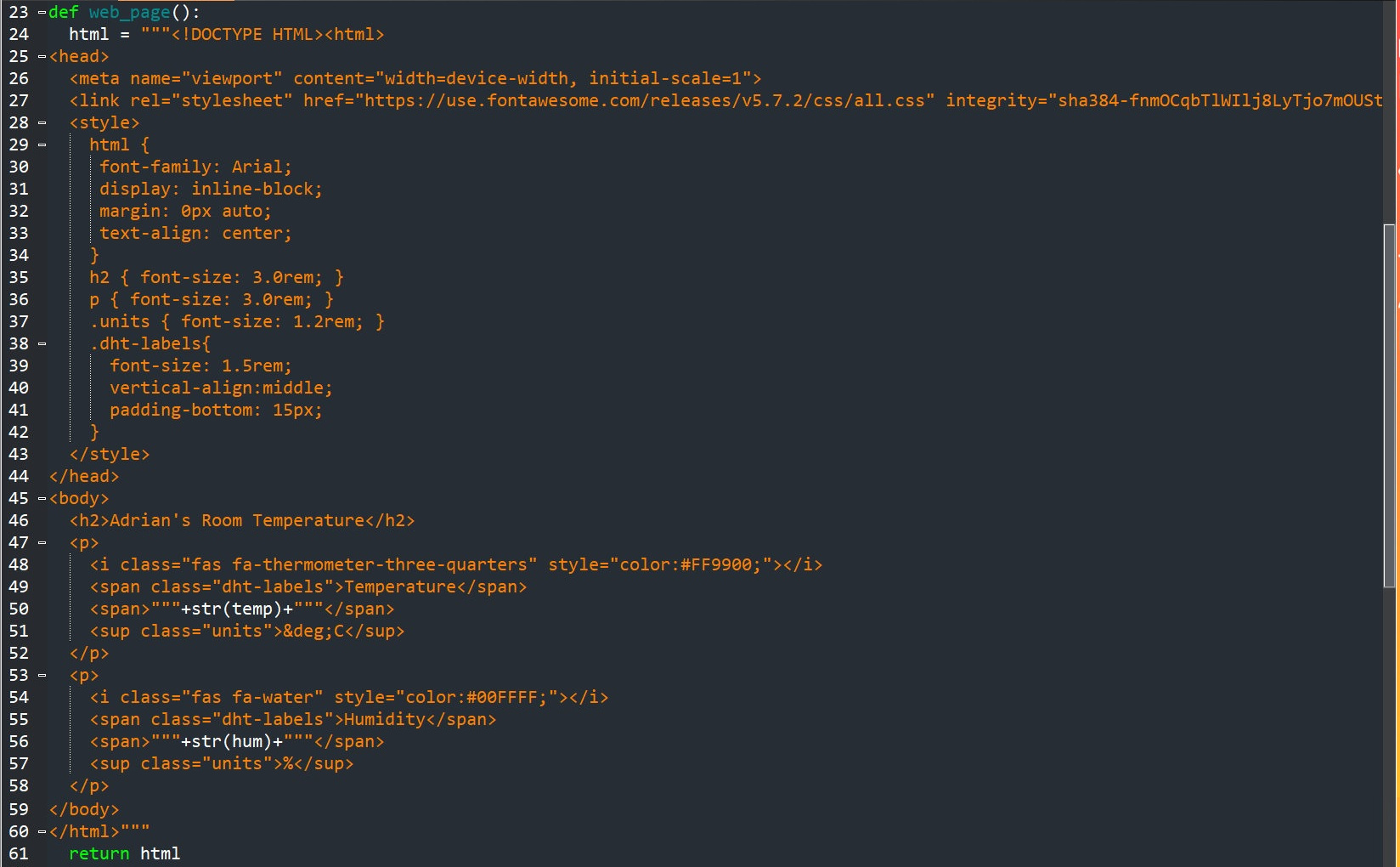
s = socket.socket(socket.AF_INET, socket.SOCK_STREAM)
s.bind(('', 80))
s.listen(5)
while True:
conn, addr = s.accept()
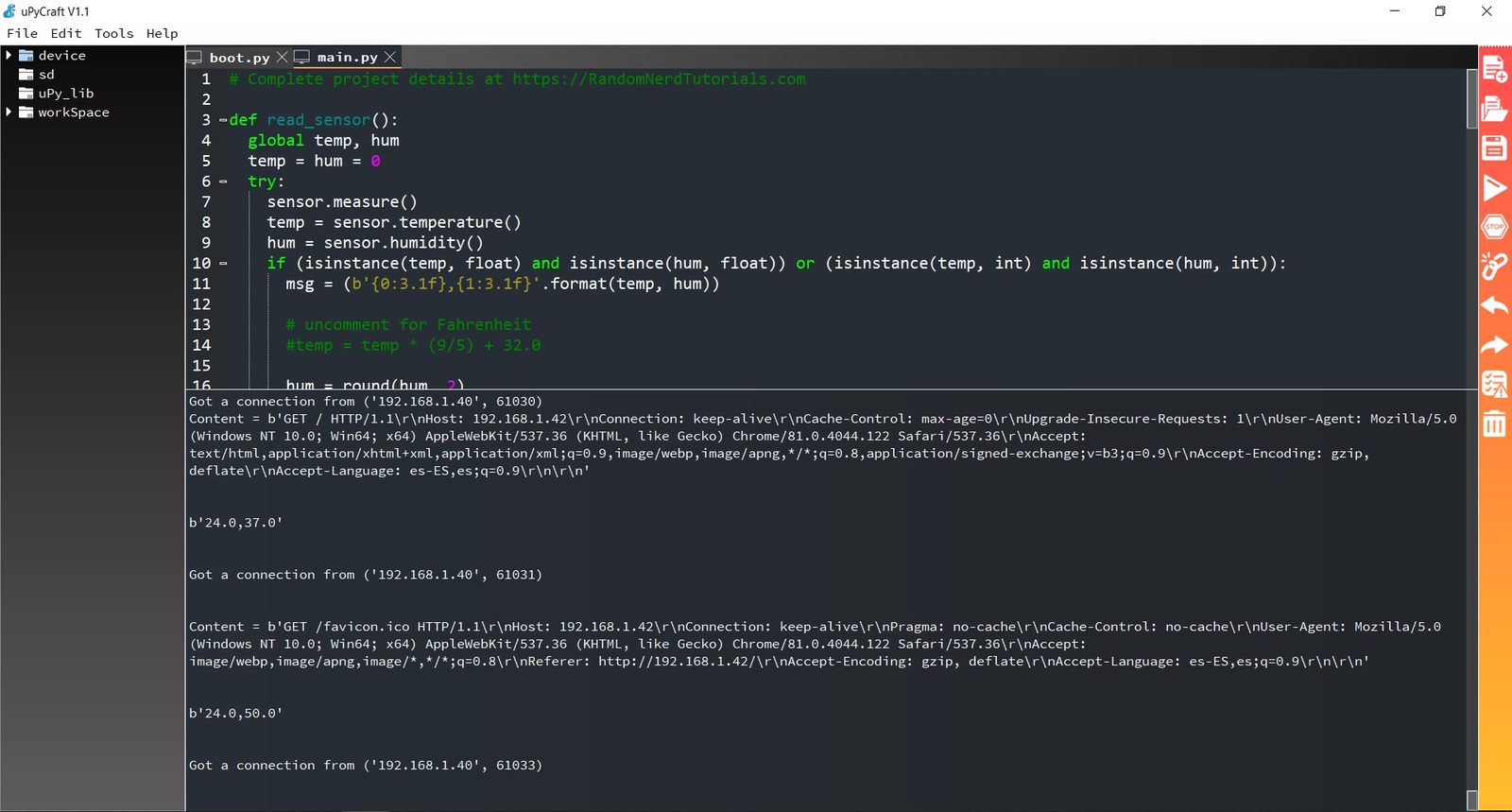
print('Got a connection from %s' % str(addr))
request = conn.recv(1024)
print('Content = %s' % str(request))
sensor_readings = read_sensor()
print(sensor_readings)
response = web_page()
conn.send('HTTP/1.1 200 OK\n')
conn.send('Content-Type: text/html\n')
conn.send('Connection: close\n\n')
conn.sendall(response)
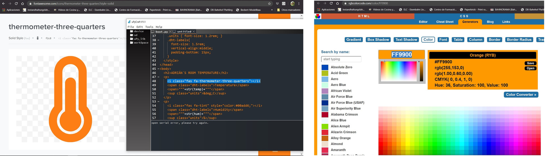
conn.close()In the code there is a bit of CSS and HTML. Like my website, the letters, logos and colors can be personalized. Here is the example of changing the logo and color.
Once we have the two files, we save them. Now we are going to load them to ESP32, for this click on the DownloadAndRun button. After uploading the files, remember press the ESP EN/RST on-board button.
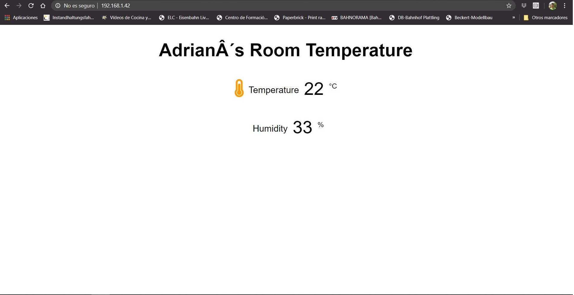
Once ESP32 has been connected, the terminal will send us the IP address where we will connect to see the Web. In my case it is 192.168.1.42
If we connect to the IP, the following appears. I test on the computer and mobile. I have a small error with the letters and with the icon of humidity (within the page of the icons there are free and paid, and by mistake I took a paid one and it is not seen).
So I modify the code of the file main.py in the HTML part, I modify the letters and the logo. To reload the code to ESP32, it is only necessary to press DownloadAndRun again, press the RST button and if necessary do Reflush Directory. It is not necessary to flash the ESP32. And this is the result. I leave a small video of the operation.
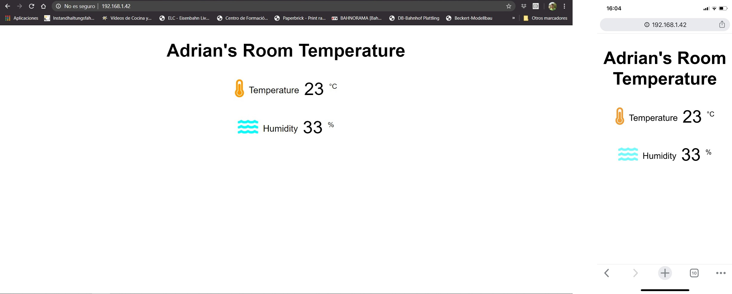
In the terminal we can also see the temperature and humidity data and what IP requests it (if it is the computer or the phone).
Conclusions.
MicroPython is another programming language that I learn. It is important to remember that you need to flash the board that you are going to use and that you will need two files; the boot.py (initialization as the Arduino void setup) and the main.py (which is always repeated as the Arduino void loop).The code, because like all you need to declare variables, libraries and then the basic instructions like if or else are similar. It is curious that you can create a very basic HTML with CSS inside a small microcontroller, this opens the door for me to use the MicroPython for simple home automation projects without having to depend on an App for a specific operating system.
Here is the files to download.
MIT App Inventor + ESP8266
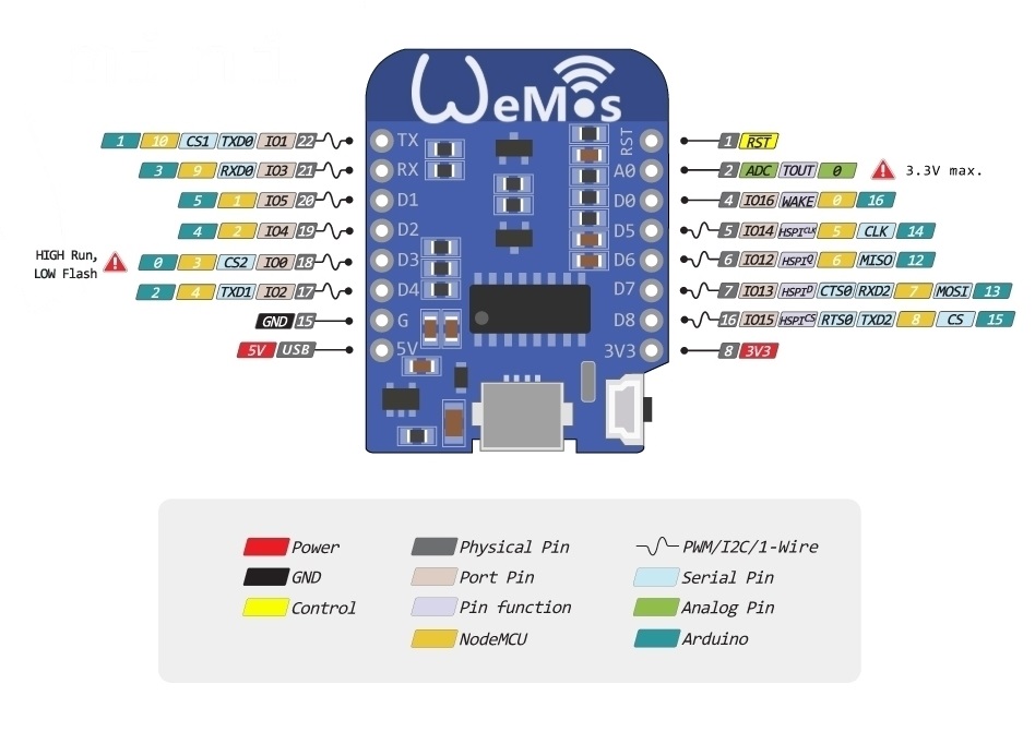
Because I have several different boards at home 🏠, I can test different programs. In this case I am going to use a Wemos D1 Mini that has an ESP8266.
This is the pinout and the components that the Wemos D1 Mini has, with the ESP8266 integrated.
In this case I am going to try to program the ESP8266 to activate a relay from an application created with the MIT App Inventor for Android smartphones. I am guided by the following tutorial. In my case I use Iphone 🍏, so I will use a Huawei that we have in the Fab Lab León. 😅
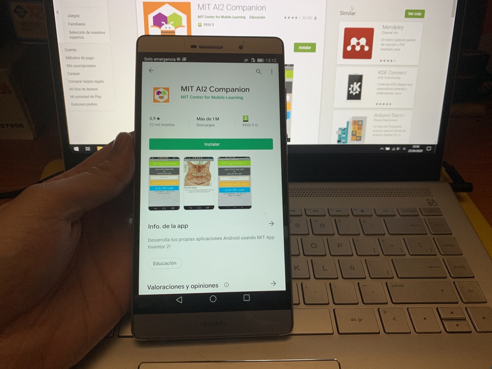
The first thing we must do is download the App MIT AI2 Companion in Google Play and put the same WIFI on both the computer and the smartphone.
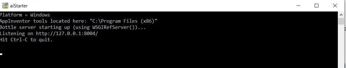
If we do not have an Android device, there is the option of using an Android system emulator. From this page we can download it. Once we have installed it, the following terminal appears, we will close and restart the computer.
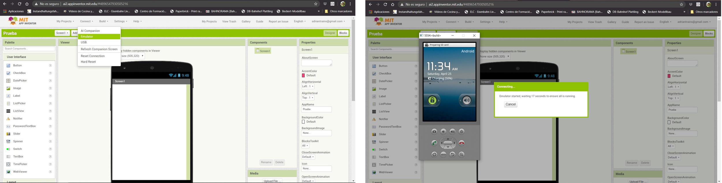
Next we open the App Inventor on the computer. As we have installed the emulator, I am going to connect it to check that it works correctly. For this we open the MIT App Inventor website, create a project. Click on Connect and then Emulator. An Android environment will start to load on our computer; It is incredible a small smartphone on the computer. 😮
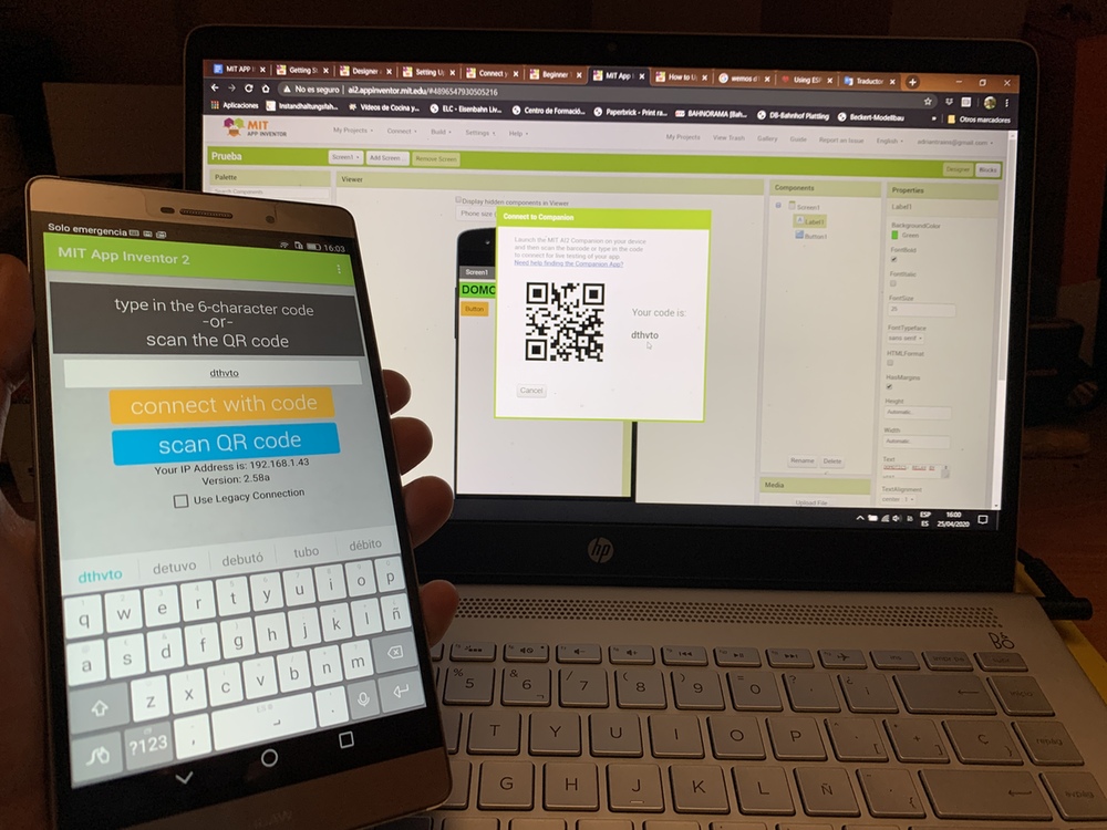
Once I have verified that the emulator works, in my case I will work with the smartphone directly. So to connect the smartphone, we will go to the Connect menu and click on Al Companion. We will see a QR code or a code that we will enter in the App.
On the MIT App Inventor website, on the right we have to choose two menus, the Designer and the Blocks. The Designer menu is used to place buttons, texts, images that we are going to see in our App. In the Blocks menu is where we put the logic to all the elements that we use in the App.
But first we start with the Designer menu. Texts, buttons, sliders or images can be added. In the menu on the left we have all the elements that we can add.

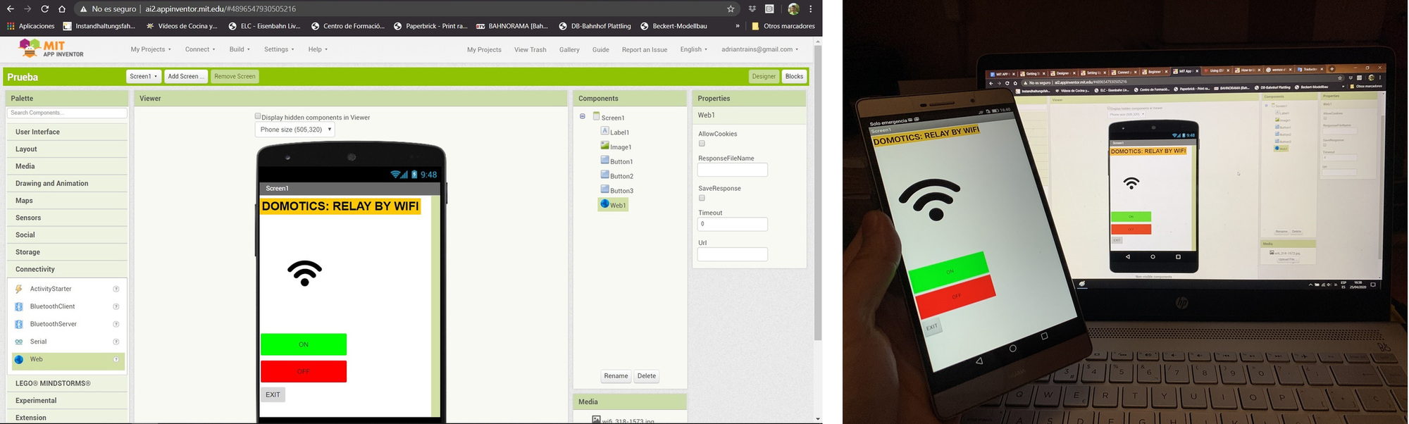
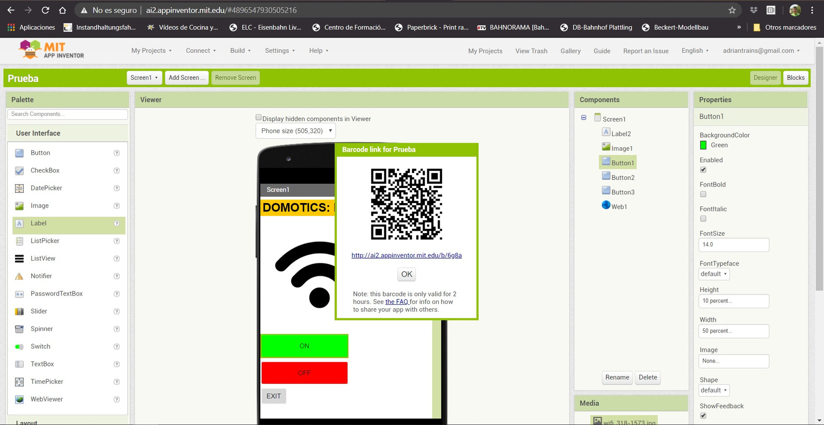
This is the result that my App will have. It has a text, an image and three buttons. The first button to turn on the relay, the second to turn off the relay and the last to exit the App. In addition to this we must add a non-visible component that is the Web. All this we can see how it looks on the smartphone.
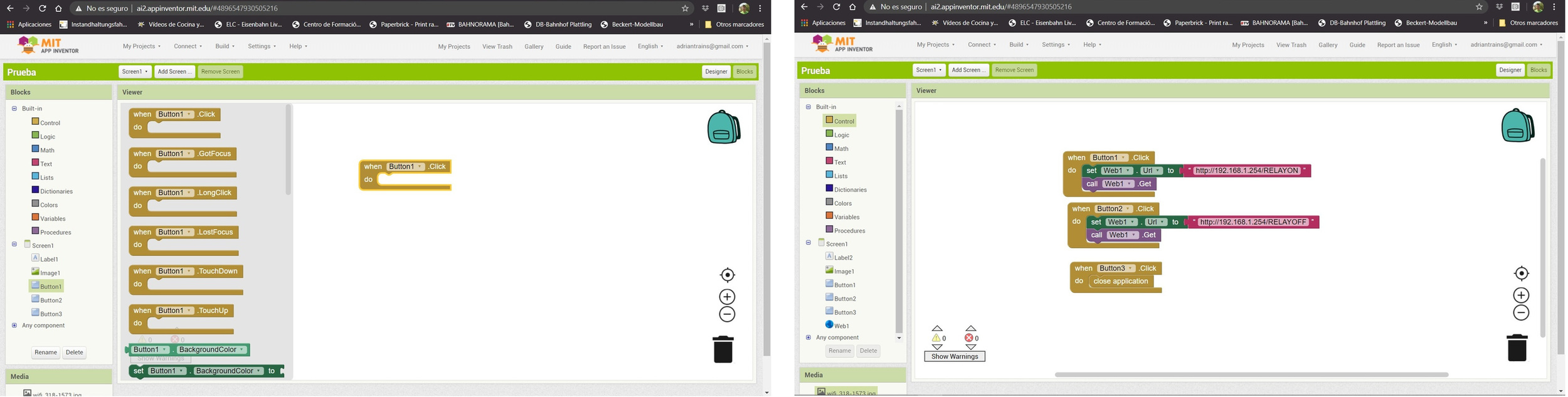
Once we have finished with the design of the App, we go to the Blocks menu, where we will put the logic to the App. It is very similar to programming in Scratch. On the left we have the different blocks grouped by the elements that we have placed in the design and also basic elements.
When we press button one, the relay will be activated. When we press button two the relay will be deactivated. And when we press button three we will exit the application. The latter is important because otherwise we will not be able to close the App unless we force its closure. Following the tutorial I put a fixed IP so that it communicates with the router more easily.
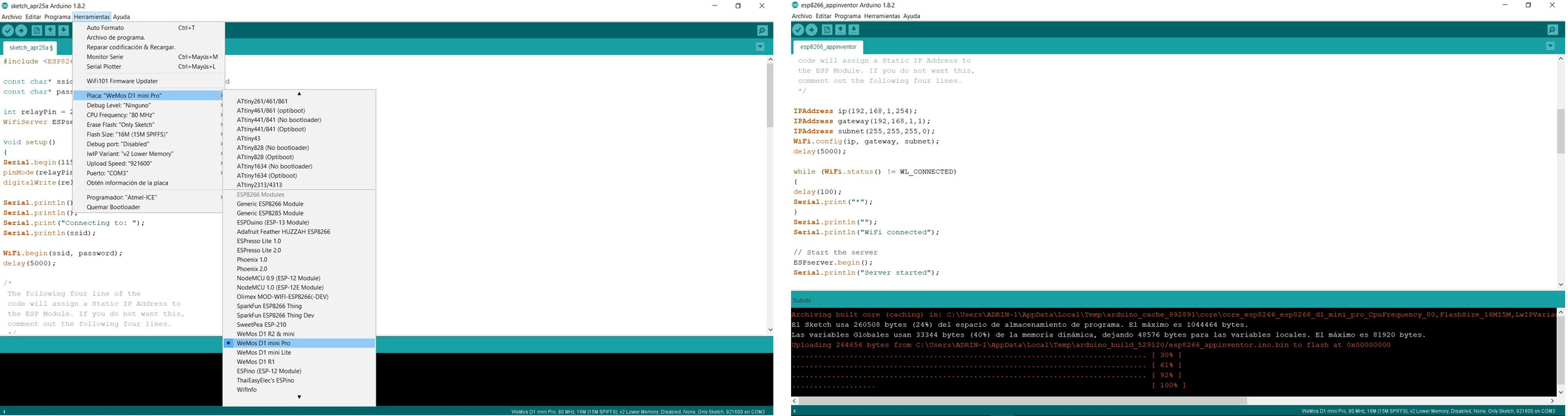
Now we pass to the program that we are going to load to the ESP8266. For this we use Arduino, we must configure the toolchain for the ESP8266 boards. Here is the link to configure it.
In the program we are going to use the GPIO2 pin of ESP8266 (D4 in the physical pinout of the Wemos D1 Mini). We must configure our Wifi and password.
//Adrián Torres - Fab Academy 2020
//Fab Lab León

#include ESP8266WiFi.h

const char* ssid = "SSID";//type your ssid
const char* password = "PASSWORD";//type your password

int relayPin = 2; // GPIO2 of ESP8266
WiFiServer ESPserver(80);//Service Port

void setup()
{
Serial.begin(115200);
pinMode(relayPin, OUTPUT);
digitalWrite(relayPin, HIGH);

Serial.println();
Serial.println();
Serial.print("Connecting to: ");
Serial.println(ssid);

WiFi.begin(ssid, password);
delay(5000);

/*
 The following four line of the
 code will assign a Static IP Address to
 the ESP Module. If you do not want this,
 comment out the following four lines.
 */

IPAddress ip(192,168,1,254);
IPAddress gateway(192,168,1,1);
IPAddress subnet(255,255,255,0);
WiFi.config(ip, gateway, subnet);
delay(5000);

while (WiFi.status() != WL_CONNECTED)
{
delay(100);
Serial.print("*");
}
Serial.println("");
Serial.println("WiFi connected");

// Start the server
ESPserver.begin();
Serial.println("Server started");

// Print the IP address
Serial.print("The URL to control ESP8266: ");
Serial.print("http://");
Serial.print(WiFi.localIP());
}

void loop()
{
// Check if a client has connected
WiFiClient client = ESPserver.available();
if (!client)
{
return;
}

// Wait until the client sends some data
Serial.println("New Client");
while(!client.available())
{
delay(1);
}

// Read the first line of the request
String request = client.readStringUntil('\r');
Serial.println(request);
client.flush();

// Match the request

int value = LOW;
if (request.indexOf("/RELAYON") != -1)
{
Serial.println("LAMP is ON");
digitalWrite(relayPin, LOW);
value = LOW;
}
if (request.indexOf("/RELAYOFF") != -1)
{
Serial.println("LAMP is OFF");
digitalWrite(relayPin, HIGH);
value = HIGH;
}

// Return the response
client.println("HTTP/1.1 200 OK");
client.println("Content-Type: text/html");
client.println(""); //  IMPORTANT
client.println("");
client.println("");

client.print("Status of the Lamp: ");

if(value == LOW)
{
client.print("ON");
}
else
{
client.print("OFF");
}

delay(1);
//client.stop();
Serial.println("Client disconnected");
Serial.println("");
}
We configure the board and the connection port. When we load the program, the terminal informs us of the load percentages and if there are any errors.
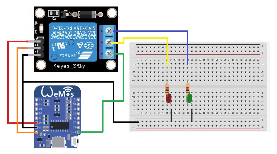
Once we have loaded the program into the ESP8266, it is time to make the electrical connection to the relay as the following schematic. The schematic I have had to do by hand because in Circuito.io and in Tinkercad Circuits there is no Wemos D1 Mini model. 😅
We have everything ready, we just need to load the App on the phone and check that it works. So we go back to MIT App Inventor to download the App in the .apk format and install it on the smartphone. To download it, we click on the Build menu. We can download it from the computer and pass it via USB to the smartphone or we can scan a QR code and download the App directly to the smartphone. Cool. 😎
Once the App is installed on the smartphone, this is the result.
App Turn on the model lights
During the regional review on Mondays, we were talking about the different possibilities of the applications, my instructor Pablo recommended that because he did not apply something that he had seen to the models.
So it occurred to me that using an app so that the public when they go to our exhibitions can interact with the model. For this I am going to create an App that when you press you turn on the light in a house. Ideal for children who visit us. 👧👦 So get to work. 💪
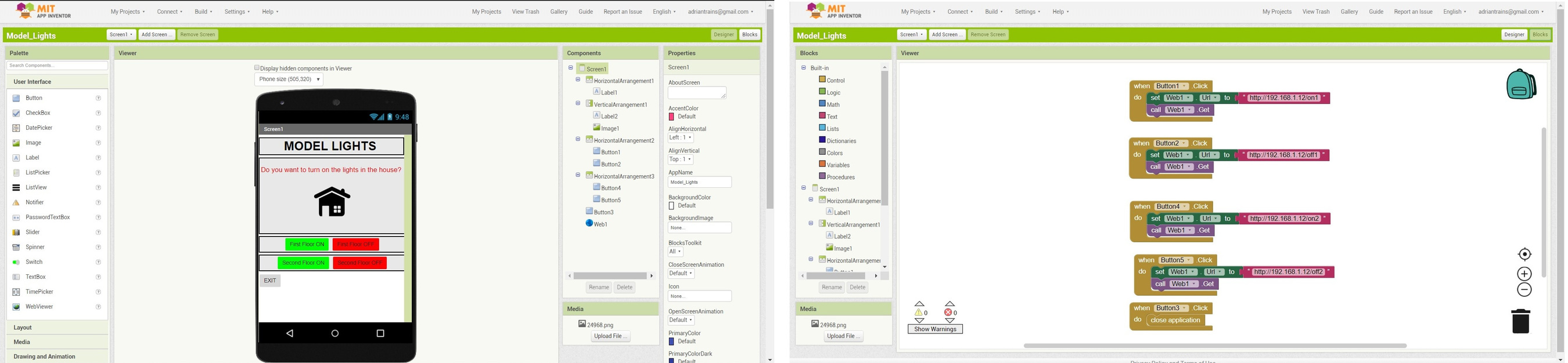
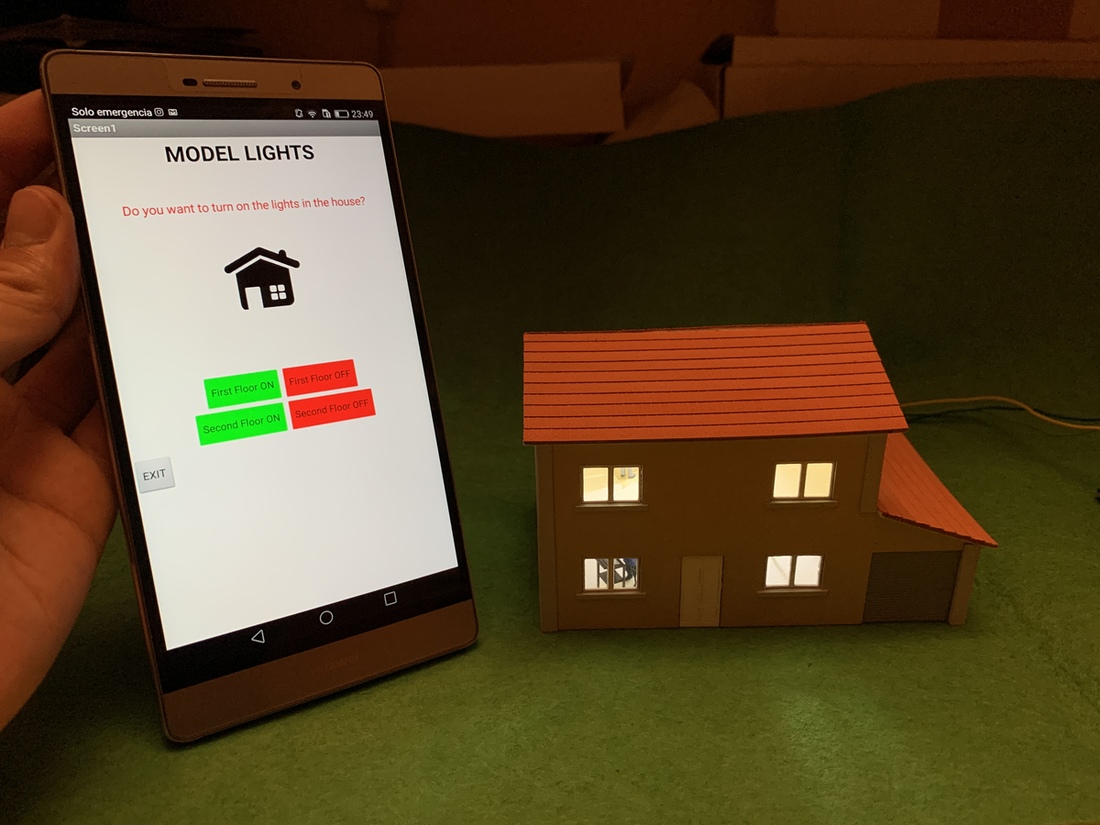
Based on the code that I used before in Arduino, I modify it so that it has two outputs for two LEDs. In the MIT App Inventor editor I create an App with 5 buttons, two to turn on the lights and two to turn off the lights and one to exit the application. Also, I have already managed to center the objects within the application.😅 The house has two floors, so I divide it into the first floor and the second floor. In the Blocks menu I place the following blocks for the five buttons.
Once I have the ESP8266 loaded with the Arduino program, and the App installed on the smartphone, I go to prepare the model, in this case a house designed and cut by me in laser. I install an LED on the first floor and another LED on the second floor. Since it will have light, I put several 1:87 scale figures on it.
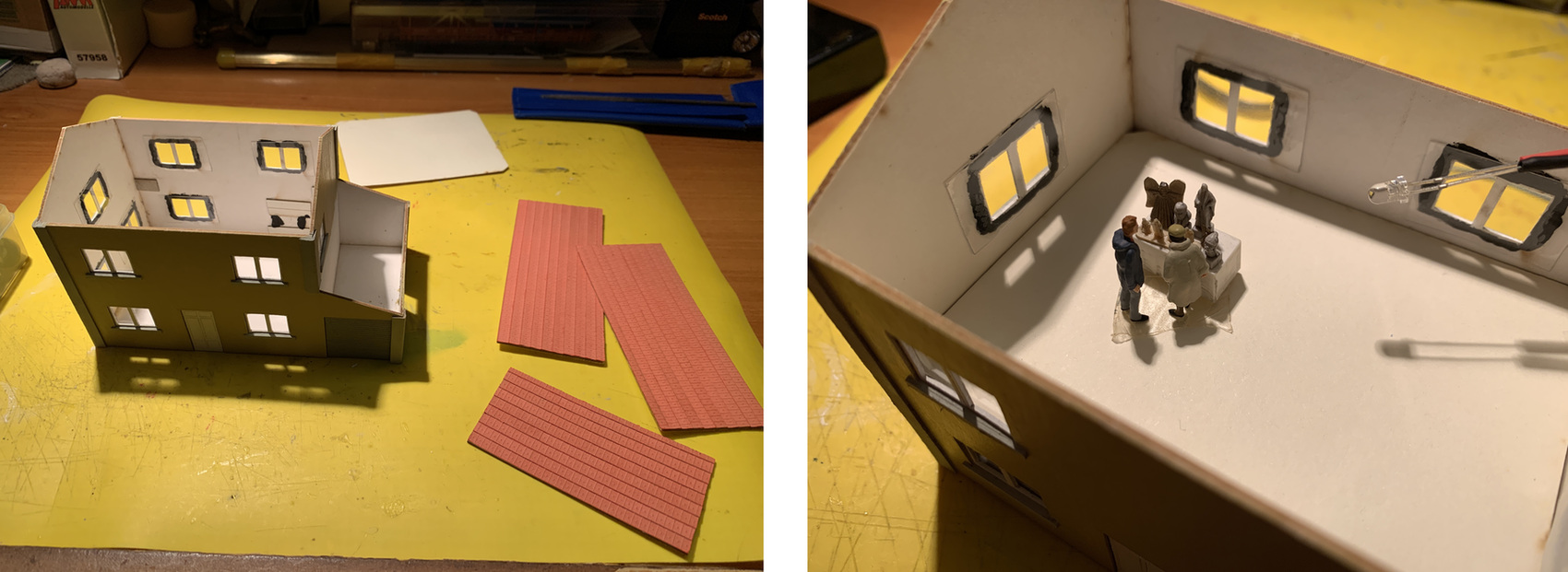
And this is the result of the lights on through the App, in the video you can see how it works. 🤩
Conclusions.
It is very easy to make a very simple App thanks to the blocks, you can program it very quickly. The page to create the App is online, and very intuitive to locate objects, and the use of QR codes helps a lot. It may also be interesting to create an application like the one I have made to turn on the lights in the house, but with other types of actuators so that people who visit the exhibitions can interact with the model.
I see it very useful so that the "Jovenes Makers" can use it and experiment with the creation of App's for their projects.
Against, since it only works for Android. In this case, MicroPython is better because it uses a Web server and does not need any App to communicate with the board.
Here is the files to download.
- Arduino ESP8266 + Relay
- App ESP8266 + Relay
- Arduino ESP8266 + Model Lights
- App Turn on the model lights
Node.js + Arduino + Sensor HC-SR04
Another language I've tried is JavaScript, using Node.js. Looking for information on JavaScript I found the following interesting page with examples of sensors using Arduino.
But going back to Node.js, I plan to create a small program that will show me the data of an ultrasound sensor in a graph found on an HTML page. For this I am guided by the following tutorial.
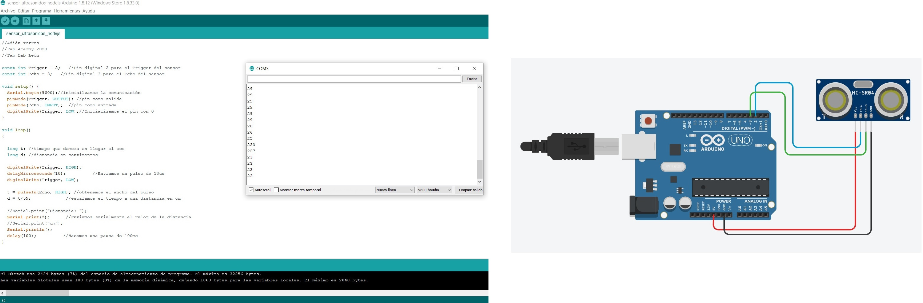
The first thing we need is to load the Arduino program that will send the sensor data through Serial. From Serial we only need the value. And this will be the schematic of connecting the Arduino with the HC-SR04 sensor.
//Adián Torres
//Fab Acadmy 2020
//Fab Lab León

const int Trigger = 2;   //Pin digital 2 para el Trigger del sensor
const int Echo = 3;   //Pin digital 3 para el Echo del sensor

void setup() {
  Serial.begin(9600);//iniciailzamos la comunicación
  pinMode(Trigger, OUTPUT); //pin como salida
  pinMode(Echo, INPUT);  //pin como entrada
  digitalWrite(Trigger, LOW);//Inicializamos el pin con 0
}

void loop()
{

  long t; //timepo que demora en llegar el eco
  long d; //distancia en centimetros

  digitalWrite(Trigger, HIGH);
  delayMicroseconds(10);          //Enviamos un pulso de 10us
  digitalWrite(Trigger, LOW);

  t = pulseIn(Echo, HIGH); //obtenemos el ancho del pulso
  d = t/59;             //escalamos el tiempo a una distancia en cm

  //Serial.print("Distancia: ");
  Serial.print(d);      //Enviamos serialmente el valor de la distancia
  //Serial.print("cm");
  Serial.println();
  delay(100);          //Hacemos una pausa de 100ms
}
Once we have loaded the program on the Arduino, we proceed to install Node.js. Node.js is a JavaScript runtime built on Chrome's V8 JavaScript engine. We follow all the steps of the installation normally.
The next thing we are going to do is create a folder where we will have our project. It will be made up of two files; index.js (where we treat the data we receive from the serial) and index.html (it will be our website where we show the data, in my case in a graph). For this we only need a code editor, in my case I will use NotePad ++. In my case I use the variable "distance" and we must put the COM port with which we have connected the Arduino, COM3.
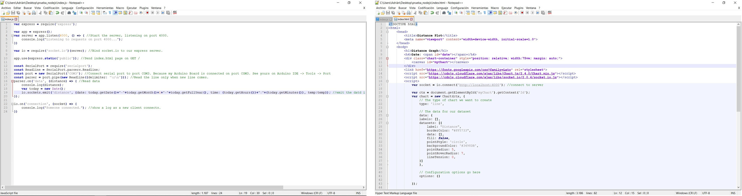
index.js
var express = require('express');

var app = express();
var server = app.listen(4000, () => { //Start the server, listening on port 4000.
    console.log("Listening to requests on port 4000...");
})

var io = require('socket.io')(server); //Bind socket.io to our express server.

app.use(express.static('public')); //Send index.html page on GET /

const SerialPort = require('serialport');
const Readline = SerialPort.parsers.Readline;
const port = new SerialPort('COM3'); //Connect serial port to port COM3. Because my Arduino Board is connected on port COM3. See yours on Arduino IDE -> Tools -> Port
const parser = port.pipe(new Readline({delimiter: '\r\n'})); //Read the line only when new line comes.
parser.on('data', (distance) => { //Read data
    console.log(distance);
    var today = new Date();
    io.sockets.emit('distance', {date: today.getDate()+"-"+today.getMonth()+1+"-"+today.getFullYear(), time: (today.getHours())+":"+(today.getMinutes()), distance:distance}); //emit the datd i.e. {date, time, distance} to all the connected clients.
});

io.on('connection', (socket) => {
    console.log("Someone connected."); //show a log as a new client connects.
})
As it happened to me in the MicroPython, the HTML code I have to put it in captures because it deconfigures my own page.
index.html
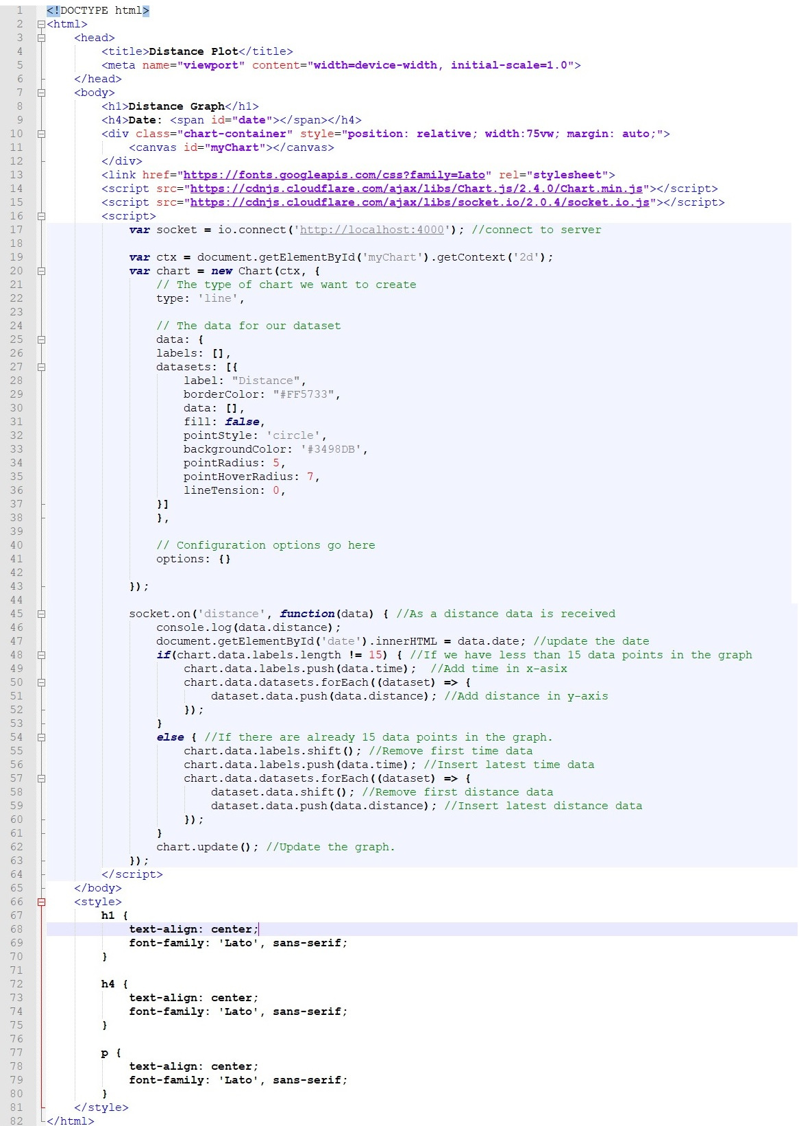
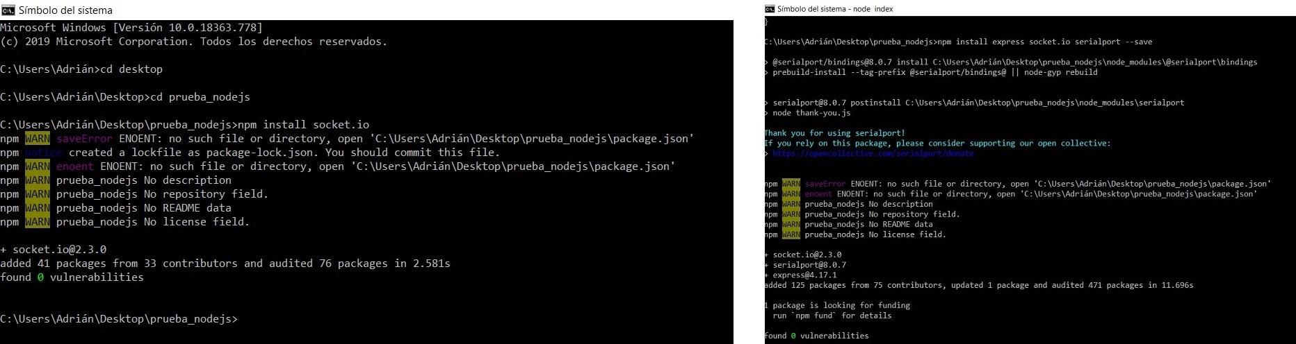
Now we go to the terminal, from where we will move to the folder where we have the project. We must install the Socket.IO, which is a library to use WebSockets. For this we will execute in the terminal npm install socket.io We will also install the express socket.io serialport library with the following command npm install express socket.io serialport --save
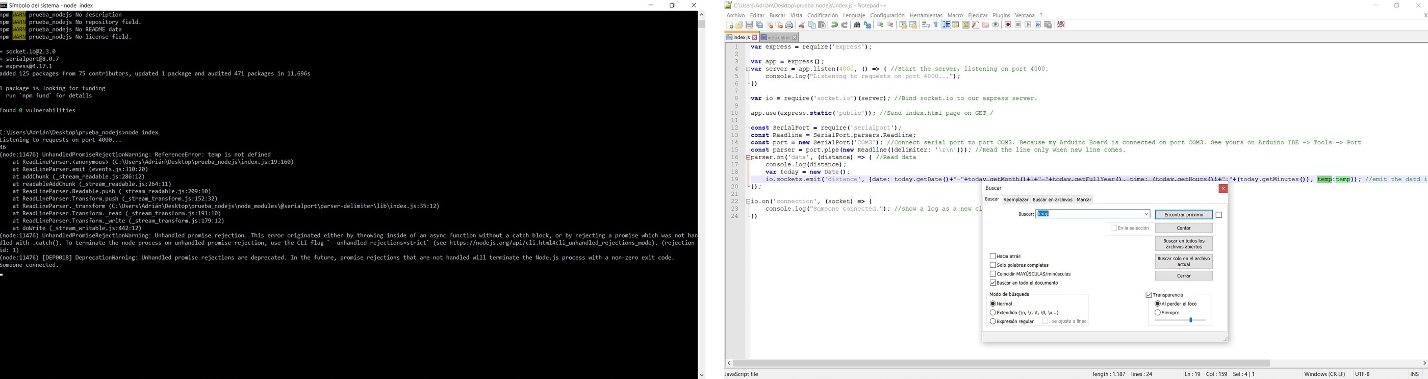
The next thing we do is run inside the folder where we have the project node index When I run it, I get an error because it can't find the variable "temp" (it's because I took the tutorial example program and don't change all variables to distance). Nothing like changing it in Notepad ++ and solved.
Once solved, I run node index again. In the terminal I start to see the values that the Arduino sends me through Serial and if I open the HTML I can see that in the graph varies the data in real time.
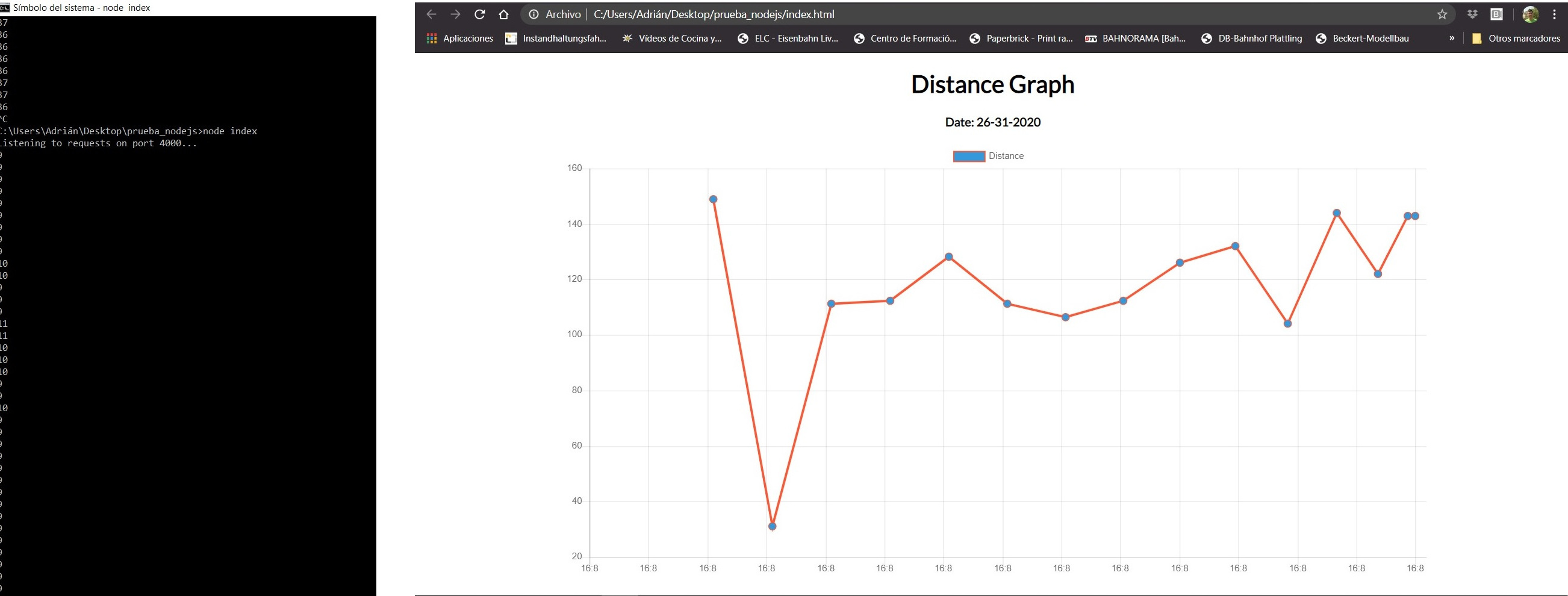
In the following video you can see how the graph works in real time and how the data varies.
Conclusions.
Using Node.js you can quickly create an interface with HTML, similar to MycroPython. Using the data obtained by Serial, you can work directly through the Node.js and the terminal, without having to install anything else. And with a code editor you can do everything. It is interesting.
Here is the files to download.
Problems with the GitLab.
On Sunday when I try to upload all my documentation, for not uploading it on Saturday, one part and on Sunday, another part, the GitLab was blocked.
I was trying to upload more than 12 MB and I had 5 commits without being able to upload. So in a desperate moment, I yelled for help and asked Nuria how I could fix it. Thanks Nuria for always being willing to help. 😘
She recommend that I do a git merge and then copy my local repository to another folder and do a git clone to have a new repository.
Then I started adding the HTML from week 12, the photos little by little and when I start uploading the assignments folder I realize that the App weighed about 3MB. So I don't upload it, I just put the link. And everything solved. What a scare. 😥
Review of the class
During the review of this class I volunteered with the MIT App Inventor in the minute 1:27:30. 😊
20200429 interface application review from Academany on Vimeo.
Files
Find below the files that I made for this assignment.
- Arduino Program Hello Distance
- Processing Random Colours
- Arduino Program Hello Reflect
- Processing Image Rotation
- Processing Level Crossing Barrier
- ESP32 + MicroPython + LED
- ESP32 + MicroPython + DHT11
- Arduino ESP8266 + Relay
- App ESP8266 + Relay
- Arduino ESP8266 + Model Lights
- App Turn on the model lights
- Arduino + HC-SR04
- Program Node.js and HTML file