7. Computer controlled machining
This week I was tasked with designing and cutting “something big” on the Shopbot CNC machine. I also learned about the several differences in bits for the CNC machine along with several safety rules that must be followed when working with the Shopbot. I also tested runout, alignment, fixturing, speeds, feeds, materials, and toolpaths for our machine as a group. You can check out that work on the student group B site.
Designing
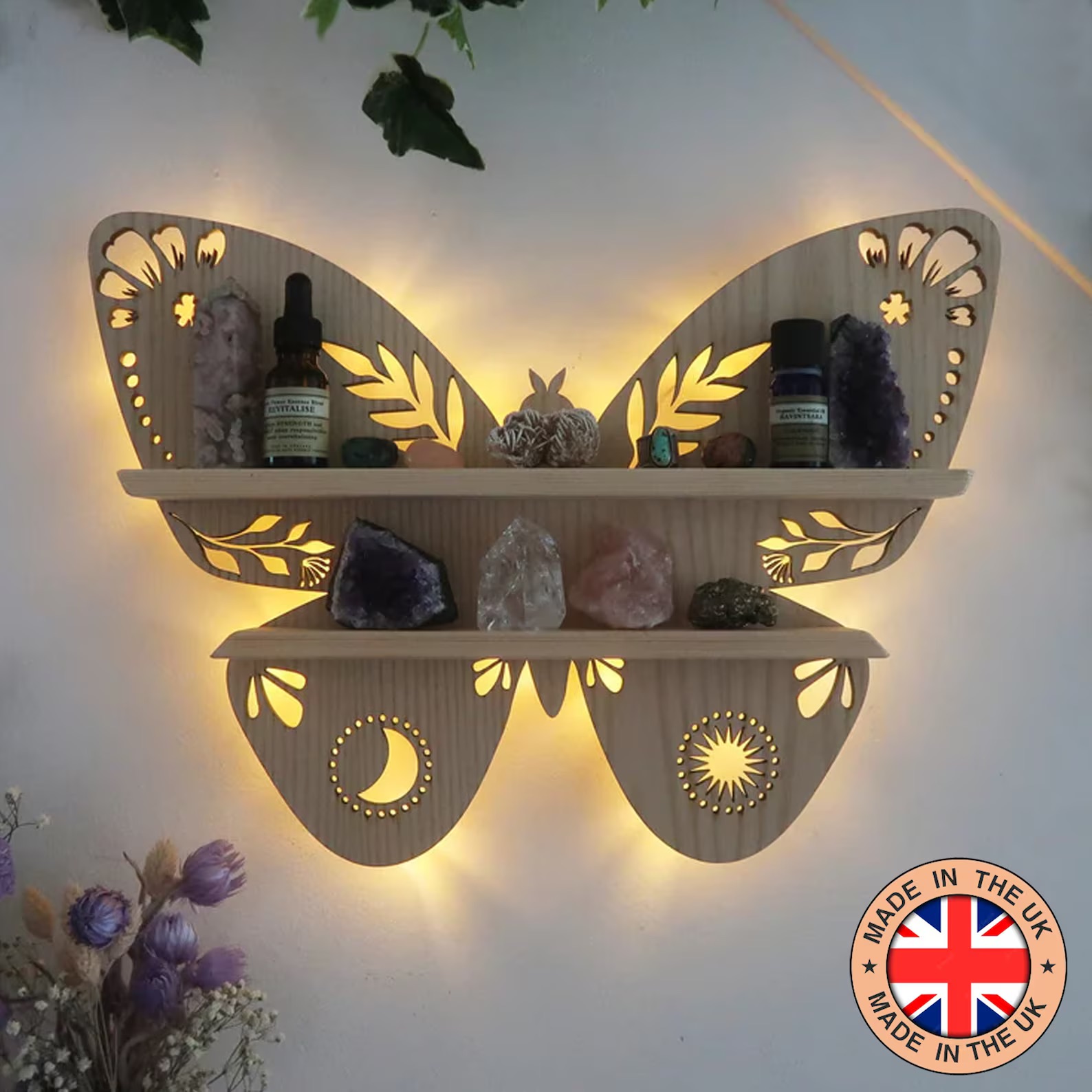
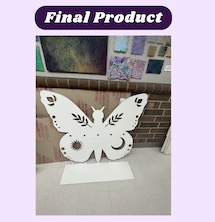
After much thought, I decided that I wanted to make a shelf that I could hang up in my room. I looked on Etsy for some inspiration and came across this beautiful butterfly shelf that I wanted to recreate, linked here.
To start, I opened Fusion 360 and imported an image of the butterfly as a canvas which I used to create the shape of the shelf. Using the fit point spline tool, I traced the shapes of the wings and then extruded it to 1/2in. I made the extrude 1/2in because that is the thickness the material should be, however, I will need to change this later because the wood I will be using won’t be precisely 1/2in. After I extruded the sketch, I created a new sketch on the surface of the body I created and made a ton of shapes and designs on one half of it. I then made a construction line down the center of the sketch and selected everything within the second sketch. After that, I mirrored everything over to the other side. When I did this Fusion 360 crashed. When it crashed the first time I thought it was a coincidence, but when I tried again and Fusion crashed again. I then realized that I had way too many items selected. Once I thought about it, I realized that not only were the lines I had created being selected but, with the way I was selecting the items, all the constraints were being selected too. To fix this, I manually selected all the items I wanted to mirror and I mirrored them. This time Fusion did not crash and I learned that when right-click and drag to select items in fusion you also select the constraints associated with them. After I put in all the designs I wanted on my shelf, I extruded the main body up to .5 in, which I would also change to my material thickness later. I then extruded all of the designs in by -100 just so that they would cut all the way through and there will be no issues later. The next thing I needed to create was the shelf and the slots for the shelf. I went about this by first making the holes for the tabs on the shelf on a new sketch. I then extruded them down the same distance I did with the designs. From there I created a new sketch in which I traced the slots I made and once I was sure they lined up and were evenly spaced I connected them with a line. I then used the move tool to relocate the sketch and I extruded the main part to be 8 in. After that, I extruded the tabs to be .5in. Once all of that was done, I finally had access to my wood, so I measured it to be .469in, so I updated all of my extrudes to match that. I then saved my file and exported it as a .dxf, so I could further work on it in Aspire. Final Fusion 360 file
Aspire
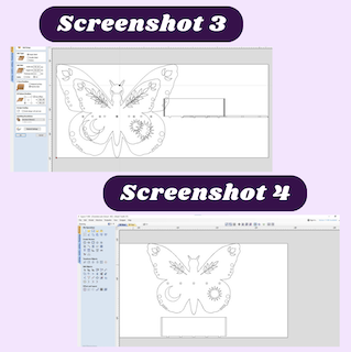
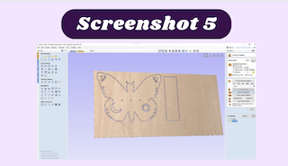
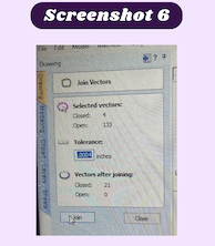
I started by editing all of the job settings to match the machine. That included making the job size 96in by 48in and the thickness the same as my material. After that, I imported my files and the first thing I notice immediately after importing my file into Aspire was how it included every iteration of what I did in fusion (screenshot 3). I then realized that I should delete all of the sketches and unnecessary bodies I then exported the .dxf file into Aspire again and the extra shapes were gone (screenshot 4). This lets me know that when you import files from Fusion 360 to Aspire, it includes everything in the design. From there I began selecting some of the various vectors I had to close them, but I noticed that there were multiple overlapping lines. At first, I was very puzzled as to why there were overlapping lines for my file and not for my friends. Then I realized because Fusion 360 includes everything into Aspire, I was also adding the overlapping lines from the extrudes I did. Normally this would be an easy fix and I would just use the original sketch, but because I originally designed the file without regard to dimensions and used the scale tool to size my project, everything would be completely messed up if I tried to fix it. I instead used Aspire to fix this issue by deleting as many of the extra vectors as possible and grouping everything else so that when I made the tool paths, there would only be one cut for it. I then calculated a tool path for everything to make sure that it would cut the way I wanted it to. What I realized, later on, was that every time I pressed calculate, It would create a new profile cut, but I found that out later on. Once I made my first calculation, I was surprised to see that not only did the tool path not cut all the way through, but it also would not display the tabs that I put in for it. After some time recalculating the tool paths with minor changes like the number of tabs or the parts I had selected, I asked Mr. Dubick for help. I then informed him that I needed to select the toolpath preview option to see precisely what would take place if it was being milled. After I selected that option, I was able to see the tabs, and the material was cut all the way through (screenshot 5). I was informed that for the inner details, I should make the profile cut and inside cut, and for the outer final cuts, I should make the outside cuts. This way nothing will turn out smaller than I anticipated. Once I made all the changes to the settings I needed, I previewed the toolpath to see if everything was correct and I noticed that the stem of the leaves on the body of my shelf were not appearing (screenshot 5). I tried several things like checking to make sure the vectors were closed by joining them and that I had the correct setting chosen (screenshot 6). I eventually tossed it up to the stem of the plant being more narrow than the bit I was using, so I created a new stem out of some lines in Aspire and I mirrored it over to the other side of the butterfly with the mirror tool (screenshoot 7). I then selected the new stem I had made and made sure that they were closed vectors again. Once all my vecors were colsed, I added dogbones to all the places where the two parts of the self would meet. The dogbones help to create a more snug fit when trying to connect wooden peices with tabs. to add the dogbones, I used the fillet tool and selected the dogbone option. After that, I clicked on each corner that needed one and that added a dogbone. I then looked over the toolpath I had and saw that everything was as it should be. After that, I sent the Aspire file that I had just finished over to the computer connected to the Shopbot. Once my file was there I had Mr. Dubick review it to make sure that everything I had done was correct. He pointed out to me that I had too many passes (5) and I needed to reduce them to 3, this would reduce the time on the job. After I changed all of the profile cut passes to 3, that way the spindle would pass around the places that need to be cut 3 time. I chose three because it’s the perfect amount of passes to conserve as much time as possible without going too deep at one time and breaking the bit. He continued to review my file. For some reason, the job time read over an hour and there was no logical reason for my job to take that long, so we looked through my file to try and figure out what was causing this issue. We eventually realized that the feed and speed settings on my file were incorrect. They were set to 40 mph and 10 mph when they should be set to 250 mph and 20 mph. Once I corrected this mistake, the time on my file went down tremendously. I also looked over my file to make sure the correct bit was selected on my file. I was using a 1/4 in bit with so that I could maximize the amount of details in my cut and the the speed of the cut. Once everything looked good from the Aspire aspect, I moved on to setting up the machine. Final Aspire file
Setup
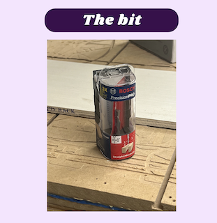
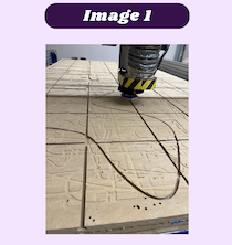
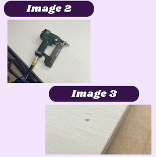
Because I was moving onto the more dangerous part of this process, I needed to tie up my hair and put on ear protection and safety glasses. Once I was properly set up with my safety equipment, followed this workflow to mill my shelf. Because I was willing right after someone else, I did not need to zero the Z axis, but I did help them zero the Z axis for there cut. To zero the Z axis, you take the disk designed for zeroing the axis and place it right below the spindle (image 1). After that using the C3 command the spindle will lower to touch the plate. Once the spindle touches the plate, it take the height it is currently at and it incorporates the thickness of the the plate to know where the bed of the machine is. The second step was to attach the material to the bed of the Shopbot. That was done using a nail gun with a special type of nail so that when my job is complete, I could simply lift my material and I would come loose easily (images 2 & 3). After my material was secure, I needed to raise the Z axis with the keyboard command J4 and move the XY back to 0,0. To cut my design I used our labs standard bit for most profile cuts, a 1/4” upward spiral bit. I used this bit because I as it spins, it carries the chips of wood up and out of my cut. This is helpful because it reduces the chances of having a fire start from the built up sawdust that would be continuously pushed against the bed with a downward spirle bit. (image of bit below). After that, I was able to start my cuts.
Milling
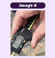
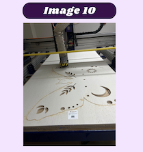
The smartest way to go about the actual milling process was to cut all of the small pieces inside of the body of the shelf, then cut out the rest of the body. I started by saving all of the tool paths for the inside of the shelf and I uploaded it to the Shopbot with an offset so it would perform an air cut and I could see how the Shop bot was going to cut. After I looked at it and everything was ok, I sent the first of the inside profile cuts to be cut (image 4). This went perfectly and I sent the second cut to the machine (image 5). This cut was progressing nicely until I dropped the emergency stop button on the floor and completely reset the Shopbot. This was very difficult to overcome without completely restarting however with Mr. Dubick’s help I was able to. The main problem was that I needed to re-zero the Z axis, but the wood that I was already fastened to the bed of the machine was preventing me from doing that. Lucky for me I already had a few pieces cut out of my board, so I was able to use that small area to re-zero the Z axis. To start I jogged the X and Y axis to the small opening I was going to use (image 6). Once the bit was over the cutout area, I used the JZ command to lower the bit at low as possible without breaking it (image 7). From there I used a few pieces of scrap wood at used them to fill the gap from the end of the bit to the bed. Once I was able to create a snug fit between the bed and the bit, I measured the thickness of the wood I used to create that snug fit (image 8). I then took that measurement and added it to the value that Z was already at, and set it to be the O for the Z axis. After the 0 was reestablished, I used the JZ, 2 command to raise the Z axis 2in. We then measured the distance from the end if the spindle to the bed of the Shopbot to see if it was 2in away (image 9). I used J2 0,0 to return the machine to the origin. After that, I started the last profile cut that I had before the machine reset and I re-milled it. That way I could see if something managed to be thrown off during that whole ordeal. Everything from there cut smoothly and to the bottom without cutting through to the bed of the machine (image 10).


Post Processing
After my cut was complete, I used the command J2 70,48 to move the spindle of the Shopbot completely out of the way. I then used a mallet and a chisel to break off all of the tabs that remained on the pieces after they were cut. I then removed both pieces from the Shopbot and lifted the remaining wood to break the nails that were stapled into the wood. Once that was finished, all that was left was to use a hammer to break off the rest of the nails in the bed and use a vacuum to remove the sawdust from the machine. I also needed to sand down the jagged edges of the shelf as well as assemble it. I chose not to fully assemble it just yet because I planned on adding resin to it and painting it white, which would be easier to do without it assembled.
Reflection
The most important thing I learned this week was how to best overcome the possibility that the machine might reset mid-cut. Another very impactful lesson I got from this week was the best way to imports .dxf files to aspire. I have learned from my mistake of importing and object that both has many sketches and extrudes within them to reduce the file down to only sketches that are necessary for the cut. Overall this week was very fun and learning how to take an idea from CAD to the CNC machine is a skill I will carry with me throughout my engineering career.