6. Electronic Design
This week I was tasked with designing a board for my final project that interacts and communicates with an embedded microcontroller, soldering a Xiao-RP2040 board, and using an oscilloscope to test to observe the operation of a microcontroller circuit board. link to my group site
TinkerCAD Simulation
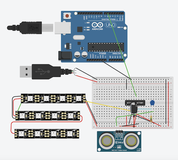
I used TinkerCAD to simulate my electronics and I was able to use a similar design that was used in a class project last semester. I started by wiring my neopixel strips. This was simply because all I needed to do was connect all the neopixels by following the arrow that the electricity would flow through. I connected the very beginning of the neopixels to the power and ground rails on my breadboard and the DIN was connected to the ATtiny 1614. Because I had more than 8 neopixels in a row I needed to connect an external power source to control the current being put into the board. After that was added I moved on to connecting the ATtiny1614 to the UDPI pin on the Arduino, so I could use the Aurduino to code my board later. I then used an Ultrasonic Sensor as a replacement for the microphone that I would use because TinkerCAD does not have a component for it. I connected it to power and ground and the signal pin to the end of a polarized capacitor. The opposite end of the capacitor was connected to a pin of the ATtiny1614 chip. A 1M ohm resistor was also connected to the ATtiny end of the capacitor and it lead to the ground, so it would prevent the capacitor from shorting (screenshot 1).
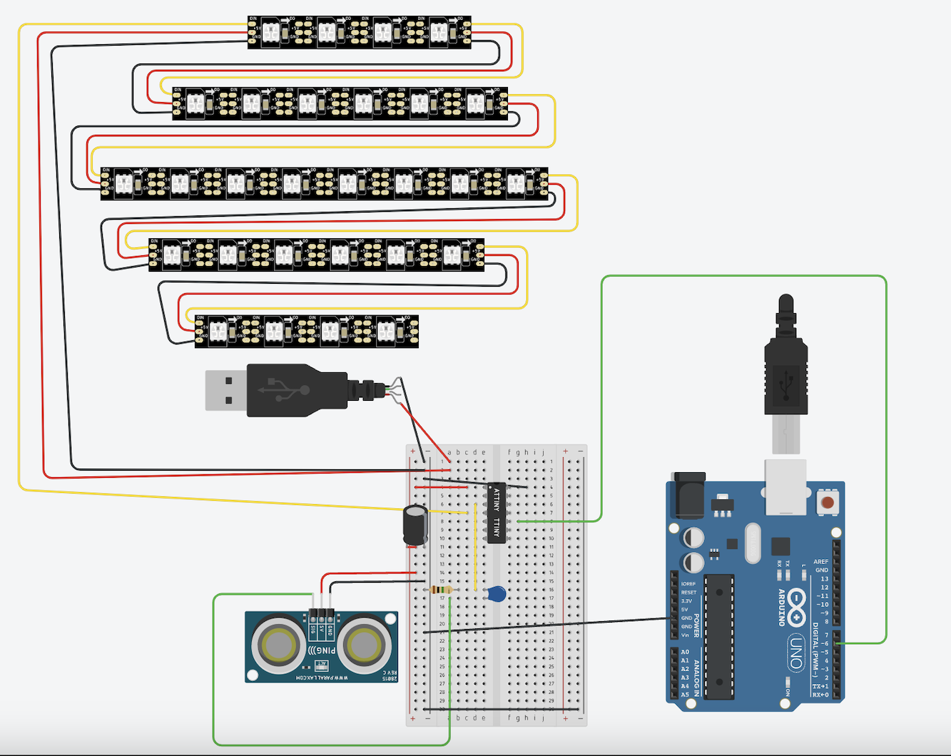
I ended up settling with a slightly different version due to reasons explained in the next section (screenshot 2). Final TinkerCAD simulation
Eagle CAD
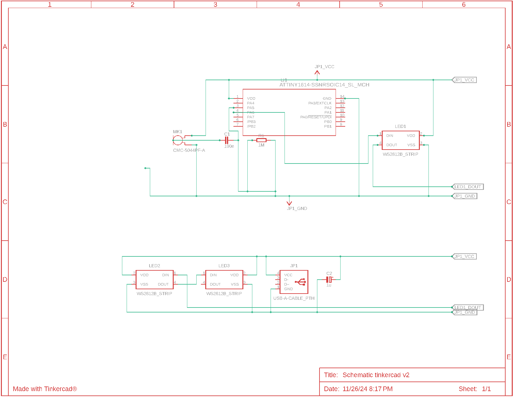
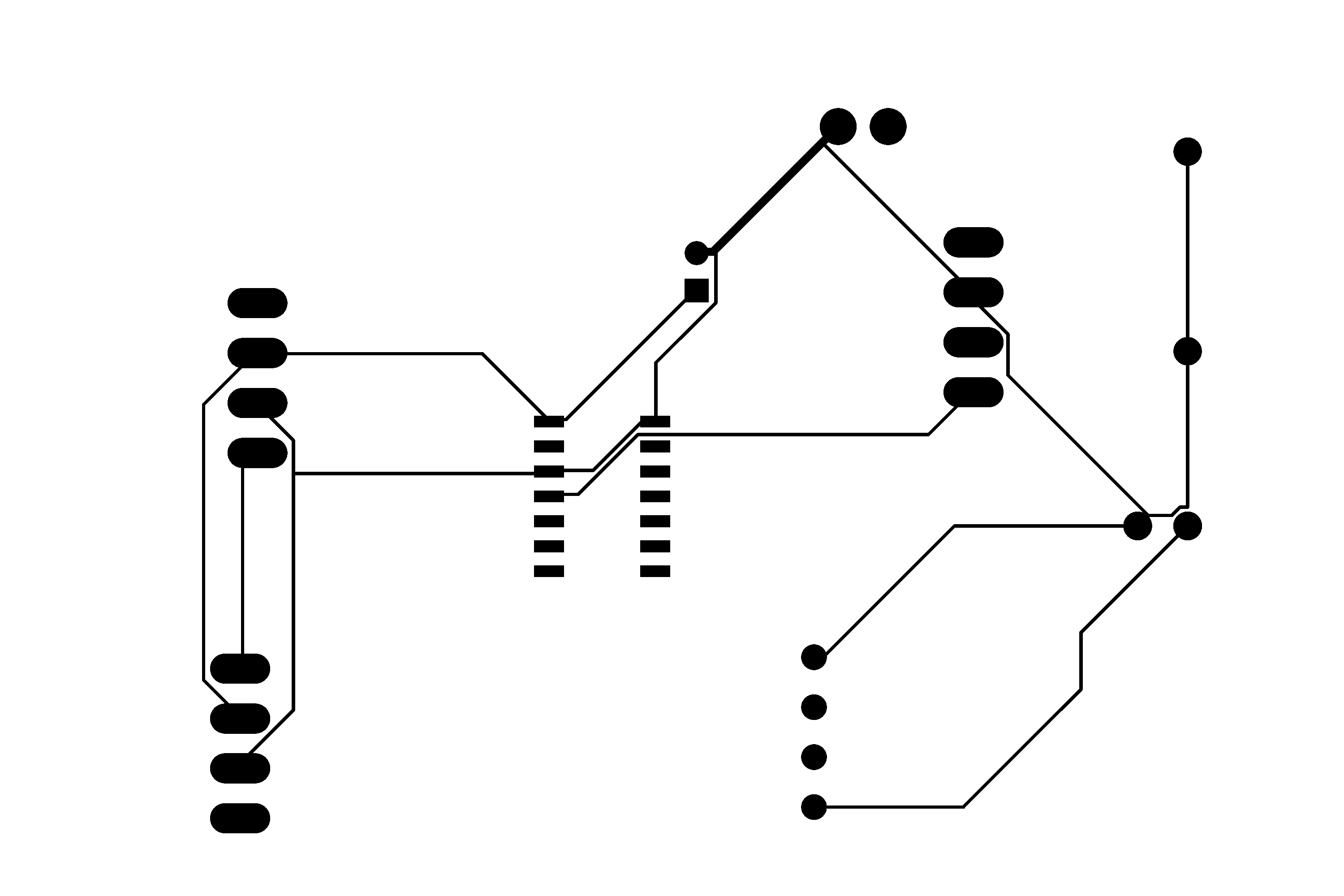
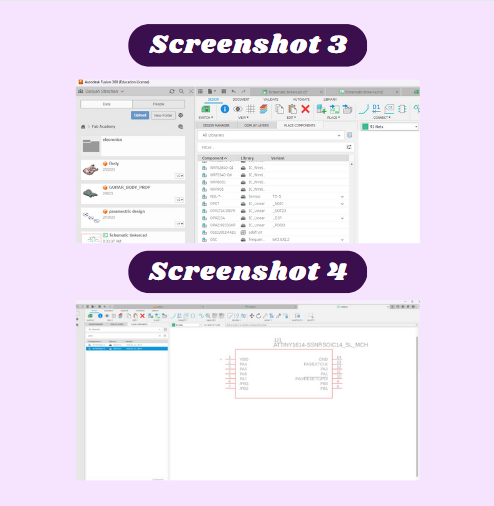
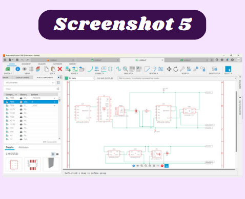
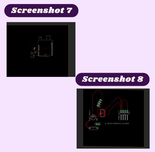
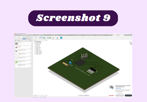
I decided to try Fusion 360 electronics first and see how I liked it and later compare it to KiCad and Eagle CAD. I watched a few tutorials online to understand how Eagle CAD worked. The first tutorial was about the project setup, the second tutorial touched on creating the schematic. I watched this tutorial and adjusted what he was doing to fit with my schematic. In the top left corner I selected the Create New Electronic Design option opened the componets library. The first problem I ran into was finding an ATtiny1614 chip to put in my design. I had to search through various different libraries to see if one was already installed, however, there were no ATtiny components, so I needed to download one and import it. I used this one from Ultra Librarian, downloaded the files, then imported them into Fusion 360 (screenshot 3 & 4). I also needed a microphone that would pick up audio from my guitar from the comppnents library, so I looked through all of the microphone options in the top and chose the one I wanted to use. I then imported the rest of the parts I needed into the sketch design area and I started to connect them. I then realized that TinkerCAD had the option to import the circuit I made to Fusion 360, so I wanted to try that out (screenshot 5). I presses the send to option in tinkercad and it opened created a schematic based on the compnents I had imported. There were a few things I needed to change such as he arduino to a ATtiny1614 and the neopixels I was using. Because there is no ATtiny1614 chip in TinkerCAD, I used 2 ATtiny chips and connected them together to get the correct number of pins and create the same effect as a 1416 chip. I also used an Ultrasonic Sensor to replace the microphone I planned on using, so I needed to replace these components in the Fusion Schematic. I also had a few wires crossing and I was not sure if that would affect my schematic, so I change them along with deleting the Ultrasonic sensor. When I attempted to change the ThinkerCad circuit, it started glitching out, so I chose to make all the changes I needed in Fusion 360. replaced the two ATiny chips with the one I imported previously and I also replaced the sensor with a microphone (screenshot 6). Once I made the schematic correct, I moved on to the PCB design. By selecting the switch to PCB tab, I was able to view all of the componets and potential connections represented by yellow lines. I used the auto route tool to automatically route all of the componets I would be using. Because more compact boards are better, I shifted a few componets around a little by dragging them with my mouse. This was challanging because it was hard to make sure that everything was connected in the correct way with the right positioning (screenshot 7). I later realized I needed to redo the Tinkercad circuit, so that’s what I did after that I looked at the PCB board and I rearranged everything so that they would all be connected correctly. The size of the traces are also very important because the larger the traces, the less likly it is to rip a trace, however there must also be space for all the traces and make sure nothing is touching. I like to use 16mm because it is wide enough to avoid tearing a trace while also leaving space for others. To change the trace size before you select them go to the manual trace router and enter the desired trace width in the Trace Width tab. After all the net connections were made, (screenshot 8) I looked at the 3D model and I adjusted the size of the board by manipulating the yellow border of the design to be the correct size. I like it to be as minimal as possible (screenshot 9). Once the traces and profile were complete I then used the manurfaturing tab selected Export Gerber Files. This created a large zip file with several unnessisary layers that I ignored. The only important parts of this zip are the Copper Top and Profile. Linked here are the Schematic and the Gerber Files for this week. To exprt a PNG of the schematic, select the CAM Processer tab near the export gerber files tab and select copper top and profile and export those images. Trace PNG linked here and Profile Outline PNG.

Kicad
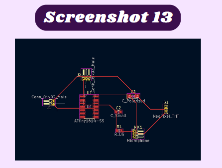
Once I started KiCad, The first difference I noticed from Eagle CAD was the fact that I did not need to import any libraries and KiCad had everything I needed. When I would click create a symbol, I could just type in exactly what I was looking for and more options would show up than in Eagle CAD. After I got all of the pieces I needed, I began to connect them accordingly . This process was easier than it was in Eagle CAD, and my final product looked like this (screenshot 10), much neater than in Eagle. I then clicked “open PCB board editor” to create the board. However, once I opened the PCB editor, I realized almost none of the components I wanted to use had a footprint attached to them (screenshot 11). To troubleshoot this, selected each component and looked at the given options. I noticed there was a footprint option and when I clicked it, I saw that there was a library that let me select from several footprints (screenshot 12). That is a nice feature because some of the components I planned of using would be attached with header pins, so having the option to change the footprint is helpful. Once I selected all the footprints, I went back to the PDB board screen and rearranged all my components. After that, I added the net connections and that completed my KiCad PCB board (screenshot 13.) Final KiCad file


Creating Housing for Electronics
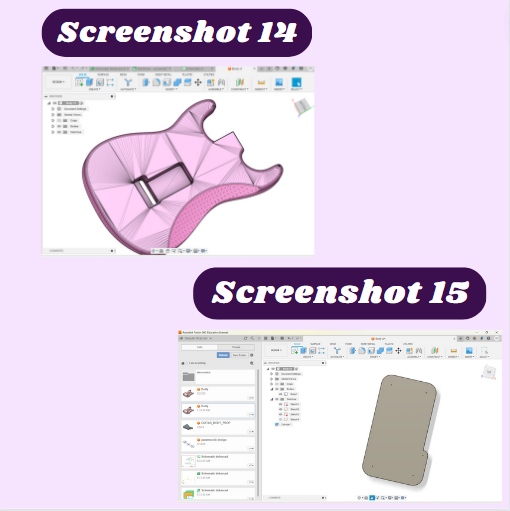
Because I will have a portion of my guitar routed out for electronics, I only need to create a plate to go overtop of the routed rectangle (screenshot 14). To do this I just got the dimensions of the area I planned to route on the guitar’s body and made a rectangular shape half an inch bigger so that I could use screws on it later. I then extruded it 1mm and put holes for the screws (screenshot 15). Final file linked here.
Reflection
Through all of this, I learned that when creating a PCB board you need to understand your schematic and have the proper connections to be successful in making your PCB board. Also having access to the correct libraries is important so that you can have precisely what you need and make sure that the footprint is what you want. The Fab Academy libraries are a very extensive source of components that contain almost everything I could need. I like KiCad over Eagle because you are able to change the footprint to anything you want. Also, ensure that when you are actually connecting the nets in the order you want so that the components function in the right way. This was very interesting to learn because the last time I made a PCB board, I had everything handed to me and I didn’t learn much but now I’ve learned a very important engineering skill.