4. Embedded programming
For this week I was tasked with using different types of micro controllers to create a circuit containing an input and an output. On my group site and I studied the ATtiny 1614 datasheet and tested it with an oscilloscope, teaching me about the max voltage and current this specific microcontroller can handle.
Arduino
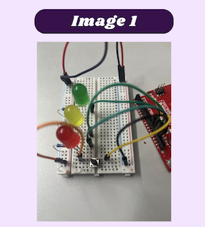
I started off with and Arduino because I have the most experience with them. The circuit I decided to make was a simple traffic light that began when I pushed a button. started off small, so that I was sure each part of the circuit was working before I made the final product. The first step I took was making sure that the LEDs would light up like a stop sign. I first took my breadboard and placed all if the LEDs in the spots I wanted them to go. From there I used a resistor and connected then to ground. After that, using pins 13, 12, and 11, I used ChatGPT to generate a stop light code that turned on the red LED for 5 second, followed by the yellow for 2 seconds, ending with the green LED for 5 seconds. Once this worked, I then wired my button. I used one one the legs of the button and connected it to ground. The other part of the LED I used was connected too pin 1o on the Arduino. The last leg I connected was put to the power rail (image 1). Again I used ChatGPT make a code that would start the other code when I pressed the button. Combining these two codes I got a working stop sign that light up after I pressed the button.
Simple traffic light code :
// Code used by Dariyah Strachan during Fab Academy 2023 sourced from ChatGPT
// Define pins for the red, yellow, and green LEDs
int redPin = 9;
int yellowPin = 10;
int greenPin = 11;

void setup() {
  // Set the LED pins as output pins
  pinMode(redPin, OUTPUT);
  pinMode(yellowPin, OUTPUT);
  pinMode(greenPin, OUTPUT);
}

void loop() {
  // Turn on the red LED
  digitalWrite(redPin, HIGH);
  digitalWrite(yellowPin, LOW);
  digitalWrite(greenPin, LOW);
  delay(5000); // Wait for 5 seconds

  // Turn on the yellow LED
  digitalWrite(redPin, LOW);
  digitalWrite(yellowPin, HIGH);
  digitalWrite(greenPin, LOW);
  delay(2000); // Wait for 2 seconds

  // Turn on the green LED
  digitalWrite(redPin, LOW);
  digitalWrite(yellowPin, LOW);
  digitalWrite(greenPin, HIGH);
  delay(5000); // Wait for 5 seconds
}
Code with button:
// Define the pin for the button
int buttonPin = 10;

void setup() {
  // Set the button pin as an input pin
  pinMode(buttonPin, INPUT);
}

void loop() {
  // Check if the button is pressed
  if (digitalRead(buttonPin) == HIGH) {
    // If the button is pressed, call the other code
    otherCode();
  }
}

void otherCode() {
  // Put the code you want to run when the button is pressed here
  // For example, you can turn on an LED
  int ledPin = 9;
  pinMode(ledPin, OUTPUT);
  digitalWrite(ledPin, HIGH);
  delay(1000);
  digitalWrite(ledPin, LOW);
}
PR2040
The next microcontroller I used was the RP2040. I based everything I did off of the circuit I made using the Arduino. However, instead if using the same pin numbers as I had in with the Arduino, I looked up a RP2040 pinout. That way I would know how to adjust the Pins I used according to how they translated in Arduino code. I chose RP2040 pins 24, 25, and 26 for the red, yellow, and green LEDs and pin 14 for the button. These RP2040 pins translated to Arduino pins 10, 18, 19, and 20. To upload my code I first needed to connect my RP2040 to my computer, to do this I first pressed the BOOTSEL button on the RP2040 while plugging it into my computer. From there I needed to install the necessary items for Arduino IDE to recognize my board. After that I made sure I was on the correct com port and I Uploaded my code.
MicroPython with Thonny
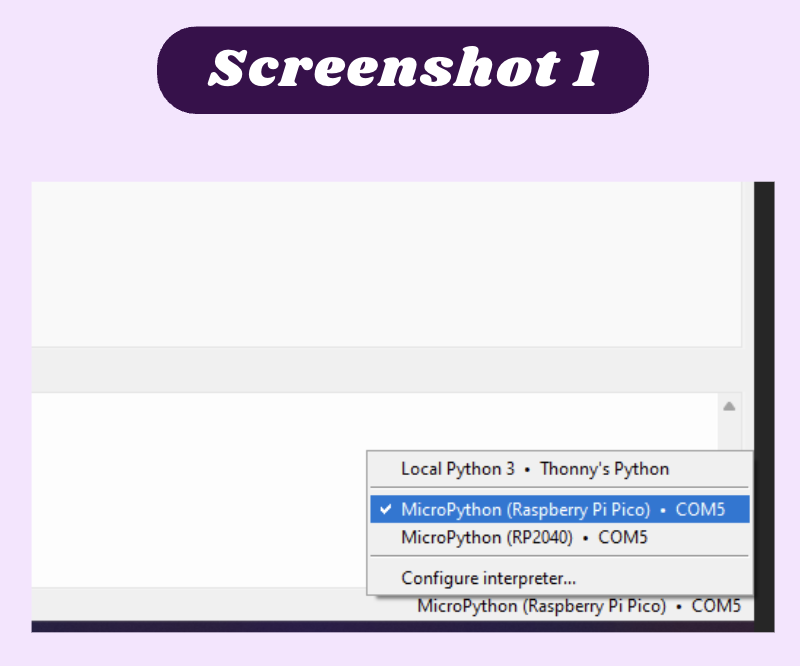
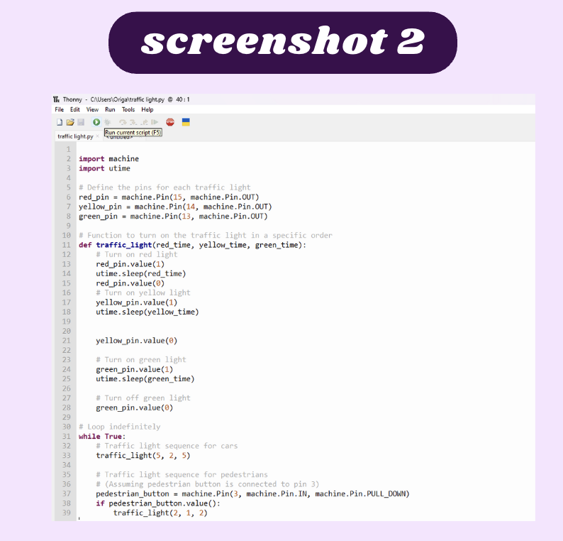
I used this guide, I coded the same traffic light as I did with the Arduino. I first needed to get MicroPython onto the Raspberry pi pico that I would be using. I went to raspberrypi.com and downloaded the required files that allowed me to run MicroPython and opened my file explorer. After that ,I dragged and dropped the files onto the raspberry pi and allowed it to download. After it downloaded, I opened Thonny and changed the COM port to COM 5, which my raspberry pi pico was connected to (screenshot 1). Once that was complete, needed to wire the LEDs. I looked up a raspberry pi pico pinout so I would know the pins I was able to use. I used three 330 ohm resisters to connect the 3 LEDs to the ground rail. I used pins 17, 19, and 20 for the green, yellow, and red LEDs. I Used chat GPT to help me make a simple traffic light code that worked with Thonny. I needed to edit a few minor things like the pin numbers and the portion about the pedestrian button that I did not need (screenshot 2). I then pressed “run current script” and waited for the LEDs to illuminate. After a few seconds, I realized that something was wrong. I looked over the code and all the settings to try and figure out what was wrong. I then realized my circuit was not connected to ground. I then took a black wire and looked at the pinout again to find a GND pin and connected it to my breadboard. I then saw the lights light up and I documented evidence of it working.
Final code:
## Code used by Dariyah Strachan during Fab Academy 2023 sourced from ChatGPT

 import machine
import utime

# Define the pins for each traffic light
red_pin = machine.Pin(15, machine.Pin.OUT)
yellow_pin = machine.Pin(14, machine.Pin.OUT)
green_pin = machine.Pin(13, machine.Pin.OUT)

# Function to turn on the traffic light in a specific order
def traffic_light(red_time, yellow_time, green_time):
    # Turn on red light
    red_pin.value(1)
    utime.sleep(red_time)
    red_pin.value(0)
    # Turn on yellow light
    yellow_pin.value(1)
    utime.sleep(yellow_time)

    yellow_pin.value(0)

    # Turn on green light
    green_pin.value(1)
    utime.sleep(green_time)

    # Turn off green light
    green_pin.value(0)
ATtiny 412
Before the start of Fab Academy, I had already soldered a ATtiny412 chip to practice my soldering skills, as well as blinking an LED with it. So I decided to blink an LED with it to see if I could still do so. The first thing I needed to do was make the Arduino I was using into a programmer using the jtag2udpi library. I first installed all of the necessary files here. I went to the files tab on Arduino IDE and pressed include library and opened the zip file I downloaded. Once that was done I opened the jtag2udpi file and sent it to my Arduino. From there. I went back to my the Arduino page with my code on it and uploaded a simple blink code using the jtag2udip programmer.
Bare metal programming
To get the LED to blink with bare metal programming, I followed similar steps to blinking and LED normally with an ATtiny412, but instead of Arduino code I used bare metal code. After I pulled up jtag2udpi and sent it to the Arduino, I opened chat GPT to help me generate a code. the first code it generated for me was as follows:
// Code used by Dariyah Strachan during Fab Academy 2023 sourced from ChatGPT
#include <avr/io.h>
#include <util/delay.h>

int main(void) {
  // Configure PB0 as an output
  PORTB.DIRSET = PIN0_bm;

  while (1) {
    // Turn on the LED
    PORTB.OUTSET = PIN0_bm;

    // Delay for 500 ms
    _delay_ms(500);

    // Turn off the LED
    PORTB.OUTCLR = PIN0_bm;

    // Delay for 500 ms
    _delay_ms(500);
  }
}
This code gave an error saying that the ports I set were invalid. I looked over this slideshow to review the naming of the ports, so I could edit the code accordingly. while looking through the slideshow I noticed this code looked a little off. I regenerated a code and got this:
## Code used by Dariyah Strachan during Fab Academy 2023 sourced from ChatGPT
#include <Arduino.h>
#include <avr/io.h>
#include <util/delay.h>

void setup() {
  pinMode(0, OUTPUT); // Set digital pin 0 as an output for programming
}

void loop() {
  // Configure PB0 as an output
  PORTB.DIRSET = PIN0_bm;

  while (1) {
    // Turn on the LED
    PORTB.OUTSET = PIN0_bm;

    // Delay for 500 ms
    _delay_ms(500);

    // Turn off the LED
    PORTB.OUTCLR = PIN0_bm;

    // Delay for 500 ms
    _delay_ms(500);
  }
}
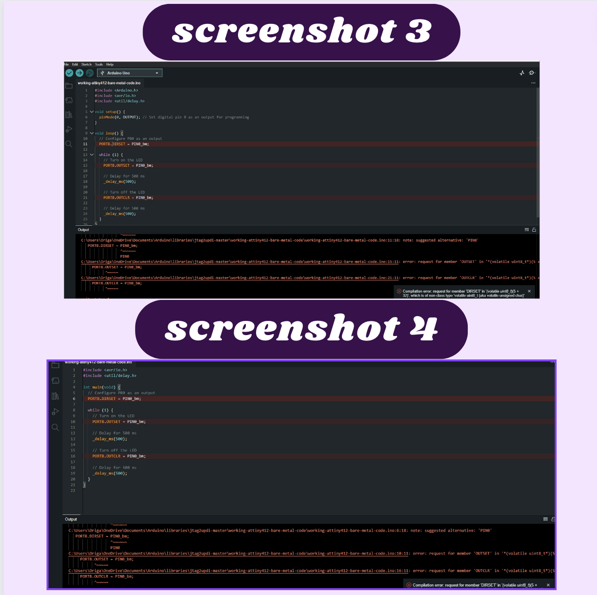
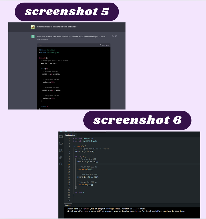
When I uploaded this code, I got the same port error message as before (screenshot 3 & 4). At this point I decided to rephrase what I was asking Chat GPT for. I instead asked for a bare metal code for an Arduino (screenshot 5). I figured if I asked for this alone, I would just change the port and upload it instead of confusing Chat GPT by asking for the code already adjusted for the ATtiny412. When I did this, I got this code :
// Code used by Dariyah Strachan during Fab Academy 2023 sourced from ChatGPT
#include <avr/io.h>
#include <util/delay.h>

int main() {
  // Configure pin 13 as an output
  DDRB |= (1 << PB5);

  while(1) {
    // Turn on the LED
    PORTB |= (1 << PB5);

    // Delay for 500 ms
    _delay_ms(500);

    // Turn off the LED
    PORTB &= ~(1 << PB5);

    // Delay for 500 ms
    _delay_ms(500);
  }

  return 0;
}
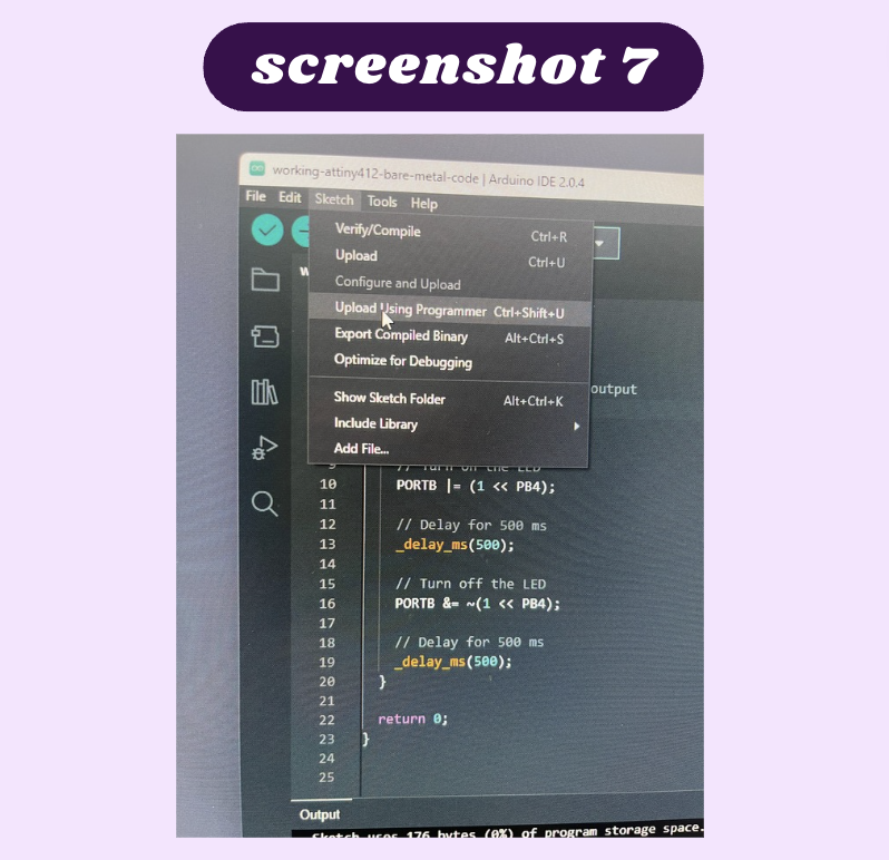
This code looked for more familiar, so I changed the part of the code that said PB5 to say PB2 which was the pin I connected my LED to, resulting in this code:
// Code used by Dariyah Strachan during Fab Academy 2023 sourced from ChatGPT
#include <avr/io.h>
#include <util/delay.h>

int main() {
  // Configure pin 13 as an output
  DDRB |= (1 << PB2);

  while(1) {
    // Turn on the LED
    PORTB |= (1 << PB2);

    // Delay for 500 ms
    _delay_ms(500);

    // Turn off the LED
    PORTB &= ~(1 << PB2);

    // Delay for 500 ms
    _delay_ms(500);
  }

  return 0;
}
I then uploaded this with the upload with a programmer(screenshot 7) option on Arduino IDE, so it would upload this code to the ATtiny instead (screenshot 6). This surprisingly worked and I was the LED flash
Reflection
This week taught me the importance of pinouts and how helpful they are when wiring electronics. It also taught me how helpful it is to start off slowly and get more complicated as we go on. I started off with something I was very familiar with, the Arduino and slowly replaced parts until I made something more complicated with the raspberry pi pico. This was very helpful for me because I was able to make sure that one component worked before replacing it, that way when troubleshooting, I could easily identify the problem and solve it.