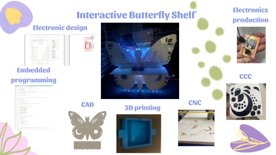
Final project
For my new final project, I wanted to expand on my project from week 7, my butterfly shelf and make it more interactive with its environment. Jada Greene used a similar concept with her interactive lamp that she made. I want to take neopixles and put them in various places on my shelf. I want to have those neopixles turn on when the lights in the room are off. I also want to have the color of the neopixles change to fit is environment similar to Mrs. Dhiman’s final project.
Pre-Project Design Specification Considerations
- What do you want your project to do?
My project will be an interactive butterfly that will react to its environment by changing color along with its surroundings.
- Will your project be inside or outside?
My project will be inside.
- Will your project be portable?
My project will be light enough that I can carry it, but it is a wall hanging, so it will mostly remain stationary.
- Will your project connect to the Internet?
No, at the moment there is no need for my project to be connected to the internet.
- Will your project use Bluetooth?
At the moment I do not plan to have my project connect via bluetooth, but in the future I may add a smaller part to my project that required bluetooth.
- Does your project use a vinyl cutter?
No, I will not need to use the vinyl cutters for anything.
- Does your project use a laser cutter?
I might use the laser cutters to engrave designs onto my butterfly, so I can add more detailed smaller designs on my butterfly.
- Does your project use a 3D printer?
Yes, I will use the 3d printers to create housing for my electrons
- Does your project use a large CNC machine (Shopbot)?
Yes, I will need a large CNC machine to create the body and the shelf of my project.
- Does your project have intelligence (Arduino, Raspberry Pi, computer)?
Yes, I will need some sort of micro controller to control the color sensor I will use along with the other sensor
- What are your project inputs?
the input will be the the color sensor that will detent the color of its
- What are your project outputs?
My outputs will be either a music analyzer, or some kind of amplifier for my project.
- What are the dimensions of your project?
I do not currently have specific dimensions for my project, but I will make it about the size of a standard electric guitar.
- What materials will you use?
will use wood, acrylic, LEDs or neopixels, metal strings for the guitar, and epoxy.
- How will you conceal the electronics?
I will put my electronics inside my guitar, or i will create a small box to conceal my electronics.
Bill of Materials
| Item | Price | Quantity | Link |
|---|---|---|---|
| RGB NeoPixels | $22.99 | 2 strips | Link |
| FR1 Board | $1.00 (per board) | 1 board | Link |
| 1/2” plywood | $24.78 | 1 | Link |
| Surface mount header pins | $4.74 | 2 packs of 8 | Link |
| Jumper wires | $6.96 | 1 pack | Link |
| Vinyl sticker sheets | $11.99 | 1 pack | Link |
| 3D Printer fillament PLA | $29.99 | 1 roll | Link |
| Adafruit ADPS9960 | $7.57 | 1 chip | link |
Milling out the body
designing:
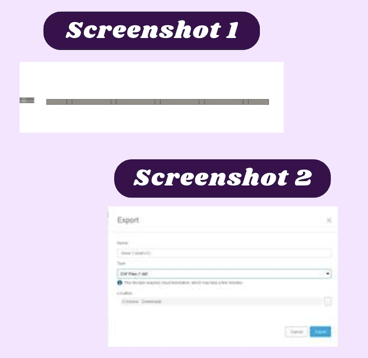
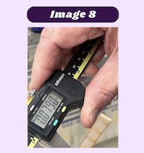
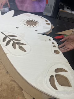
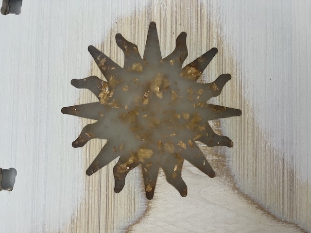
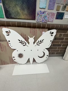
I made the body of the butterfly shelf in week 7 where I further expand on the process. After much thought, I decided that I wanted to make a shelf that I could hang up in my room. I looked on Etsy for some inspiration and came across this beautiful butterfly shelf that I wanted to recreate, linked here. To start, I opened Fusion 360 and imported an image of the butterfly as a canvas which I used to create the shape of the shelf. Using the fit point spline tool, I traced the shapes of the wings and then extruded it to 1/2in. I made the extrude 1/2in because that is the thickness the material should be, however, I will need to change this later because the wood I will be using won’t be precisely 1/2in. After I extruded the sketch, I created a new sketch on the surface of the body I created and made a ton of shapes and designs on one half of it. I then made a construction line down the center of the sketch and selected everything within the second sketch. After that, I mirrored everything over to the other side. When I did this Fusion 360 crashed. When it crashed the first time I thought it was a coincidence, but when I tried again and Fusion crashed again. I then realized that I had way too many items selected. Once I thought about it, I realized that not only were the lines I had created being selected but, with the way I was selecting the items, all the constraints were being selected too. To fix this, I manually selected all the items I wanted to mirror and I mirrored them. This time Fusion did not crash and I learned that when right-click and drag to select items in fusion you also select the constraints associated with them. After I put in all the designs I wanted on my shelf, I extruded the main body up to .5 in, which I would also change to my material thickness later. I then extruded all of the designs in by -100 just so that they would cut all the way through and there will be no issues later. The next thing I needed to create was the shelf and the slots for the shelf. I went about this by first making the holes for the tabs on the shelf on a new sketch. I then extruded them down the same distance I did with the designs. From there I created a new sketch in which I traced the slots I made and once I was sure they lined up and were evenly spaced I connected them with a line. I then used the move tool to relocate the sketch and I extruded the main part to be 8 in. After that, I extruded the tabs to be .5in (screenshot 1). Once all of that was done, I finally had access to my wood, so I measured it to be .469in, so I updated all of my extrudes to match that. I then saved my file and exported it as a .dxf (screenshot 2), so I could further work on it in Aspire. Final Fusion 360 file
milling:
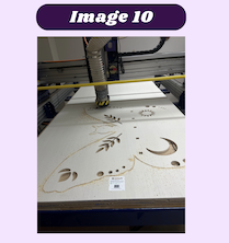
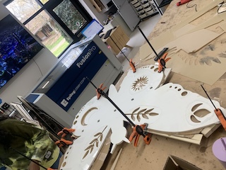
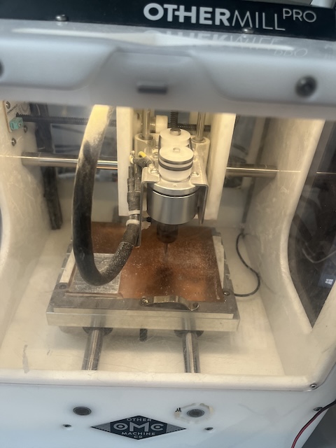
The smartest way to go about the actual milling process was to cut all of the small pieces inside of the body of the shelf, then cut out the rest of the body. I started by saving all of the tool paths for the inside of the shelf and I uploaded it to the Shopbot with an offset so it would perform an air cut and I could see how the Shop bot was going to cut. After I looked at it and everything was ok, I sent the first of the inside profile cuts to be cut (image 4). This went perfectly and I sent the second cut to the machine (image 5). This cut was progressing nicely until I dropped the emergency stop button on the floor and completely reset the Shopbot. This was very difficult to overcome without completely restarting however with Mr. Dubick’s help I was able to. The main problem was that I needed to re-zero the Z axis, but the wood that I was already fastened to the bed of the machine was preventing me from doing that. Lucky for me I already had a few pieces cut out of my board, so I was able to use that small area to re-zero the Z axis. To start I jogged the X and Y axis to the small opening I was going to use (image 6). Once the bit was over the cutout area, I used the JZ command to lower the bit at low as possible without breaking it (image 7). From there I used a few pieces of scrap wood at used them to fill the gap from the end of the bit to the bed. Once I was able to create a snug fit between the bed and the bit, I measured the thickness of the wood I used to create that snug fit (image 8). I then took that measurement and added it to the value that Z was already at, and set it to be the O for the Z axis. After the 0 was reestablished, I used the JZ, 2 command to raise the Z axis 2in. We then measured the distance from the end if the spindle to the bed of the Shopbot to see if it was 2in away (image 9). I used J2 0,0 to return the machine to the origin. After that, I started the last profile cut that I had before the machine reset and I re-milled it. That way I could see if something managed to be thrown off during that whole ordeal. Everything from there cut smoothly and to the bottom without cutting through to the bed of the machine (image 10).


Resin
first layer:
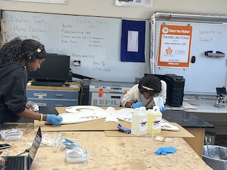
The first step I took in this process was Painting a clear coat of resin on the inside of my cutouts that I would be putting resin into. To do this I put on gloves and gathered a silicon mixing cup and spatula, a disposable cup, and a popsicle stick. I took sheets of cardboard and put them underneath the area where I would be working, that way I would not make a mess. I poured in a 1:1 ratio of part A and part B of the resin. I then proceeded to mix the two parts together for 5 minuets. Once the 5 minuets were complete, I slit the resin into 2 cups, one for me and one for my sister, so we could conquer the job faster. We used cheap paint brushes to spread the resin around the inside of each area I wanted to put resin in. Because the chemical reaction that takes place between parts A and B when resin in mixed is exothermic, as we were painting the resin on, we could feel the heat being emitted from the reaction. Once we finished the first coat of resin I left it to cure overnight.
prep:
Because resin is self leveling, it is very important to make sure that what you are pouring onto is as waterproof as possible, so the resin does not leak everywhere both creating a mess and more work later on while sanding. To prevent this, I used silicone caulk to create a border around the areas I wanted to pour into. That way when I over-poured the resin, the caulk would stop it from spreading all over the project. Along with the caulk, I also used tape on the bottom of the areas I needed it on. I used the take because my wood was very bowed and when I would pour it the resin would leak out everywhere. On top of adding the tape, I also took pieces of scrape wood and clamps to keep the seal tight.
final pour:
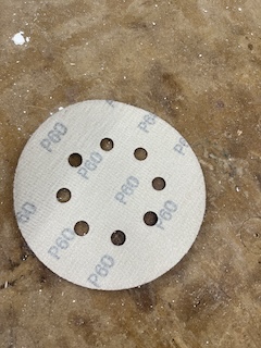
After the first pour, there several spots where the tape on the cardbord caused indentations on the resin that made it look warped. I decided to try and color match the resin as best I could and pour another coat on top of the warped parts to will them in. To start, I sanded the resin with 60 Girt sand paper to allow the new resin to stick better.
After the resin was sanded, I mixed equal amounts of part A and part B resin and added separated them into batches. I added small amounts of pigment to each bactch until I was happy with the color. I poured the resin into the places that needed it and waited 24 hours for it to dry.

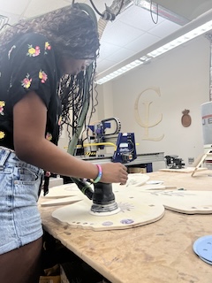
Sanding
After the resin was fixed and poured to how I liked it, I needed to sand off all the excess resin. I started with 60 grit and used 80 grit, 100 grit, 120 grit, 180 grit, 220 grit, 260 grit, 300 grit, 350 grit, 1000 grit, and 4000 grit sandpaper in asending order to sand and polish the resin. until with was completly smooth and the resin looked clear.
Electronics
testing:
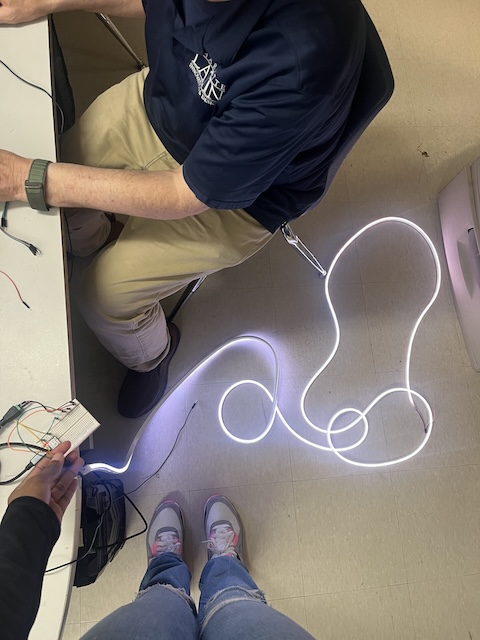
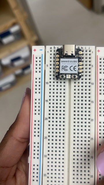
To start off I used the previous knowledge I had from my work during outputs week to start off with testing. Because I was using the the WS2811 LED instead of the WS2812B (neopixels), I wanted to test out simple codes to make sure the strip worked. At first I had trouble getting the LED strip to turn on. I was originally using a 5v power supply and a seeed RP2040, the code was uploading to the board with no problem so I was very confused. I thought the LED strip wasnt working and started to look for a new one on amazon; then I noticed the ones on Amazon used a 12v power supply. I switched out the power supply and the strip turned on solid white.
I then attempted to upload a strandtest example code but it was not working. I tried to move my wiring to the other side of the LED strip just in case it was simply on the worng side, again it just lit up white and there was no change to the colors. I had no idea what was wrong with the strip and I thought it was possible that the strip I was using was not addressable, so I took another WS2811 strip and wired it the same way I did with the privious one. From there I noticed the strip was lighting up however the colors and patterns were not correct. It was sparatically flashing random colors attempting to respond to the code I had uploaded. I assumed this was due to a faulty ground or a bad connection somewhere so I adjusted all of my wires and made sure eveything was sharing a ground. This did not fix my problem however when I looked at the chip I was using, I noticed that some of the solder connections may have been the problem. because I was borrowing someone elses chip, I returned it to them and decided to solder my own, I made sure to melt the solder extra long to ensure there were no cold solders and I plugged the newly soldered chip into the breadboard.
After I replaced the chip, I reuploaded the code and then nothing was happening. While looking over my code again, I noticed I did not have the correct pin, once I changed the pin in the code back to what I had it to when I first started testing, the LED strip started working. Once I had the new LED strip working I took the old one I was trying to use and wired it the same way. This made the strip finally start working, however, I noticed they were pretty dull, so I looked at the code where the brightness was and noticed it was at 50. I changed it to 200 and uploaded the code and the LED strip got brighter. The next thing I needed to focus on was the color sensor and getting it to work with the LED strip. Final PCB file
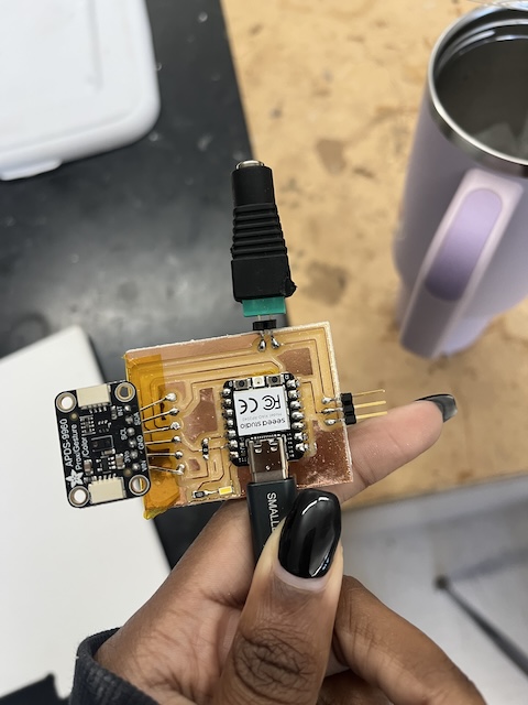
Electronic production
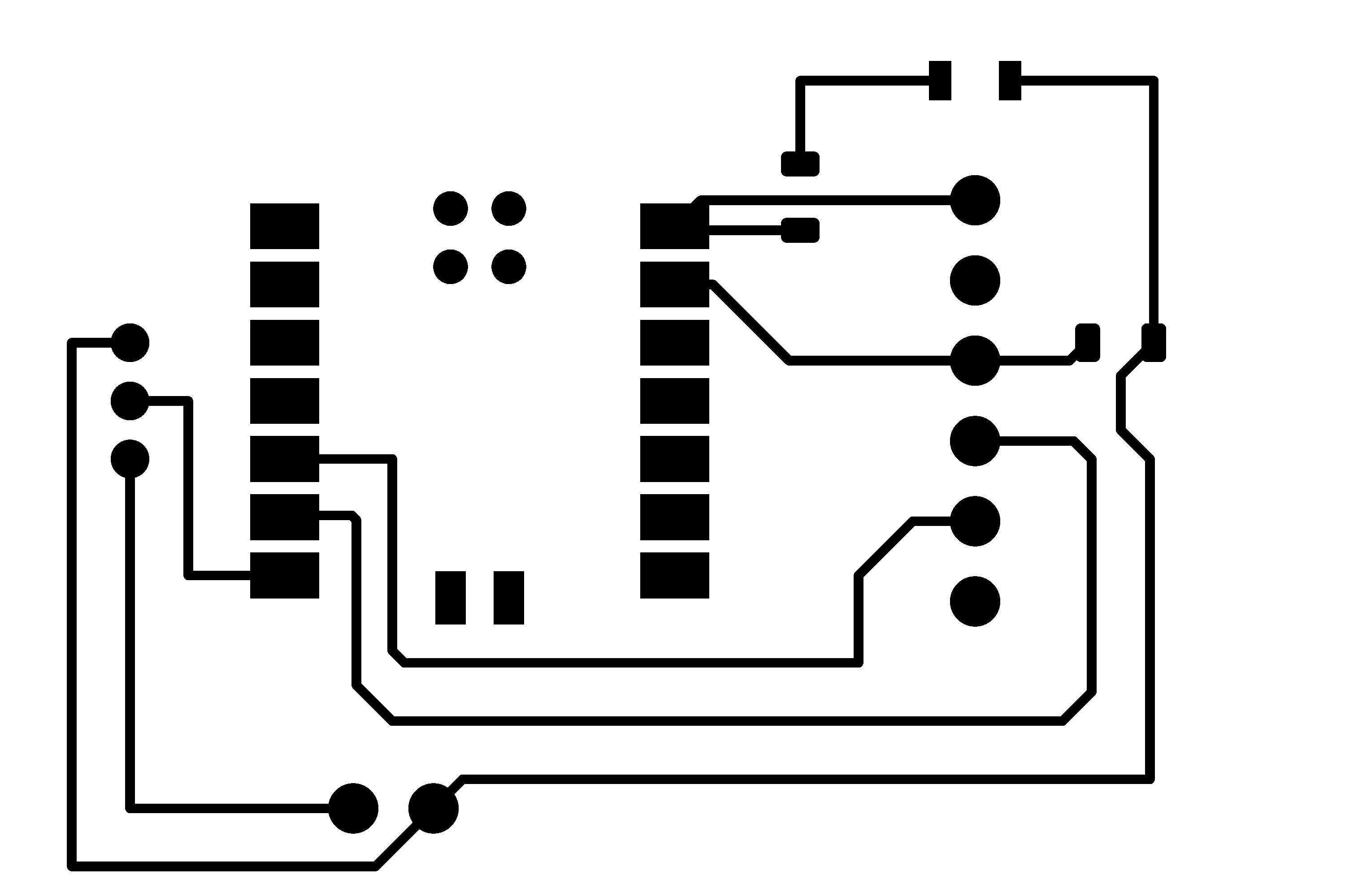
For this board I wanted to reduce the amount of neopixels I would be using for my final project, so I decided to only light up the perimeter of the shelf. I needed two sets of four header pins for the neopixels and for the color sensor. I connected the header pins for the color sensor to the ground, 3.3V, SDA, and SCL pins of the color sensor. I then moved onto the neopixles. I used neopixels that had red, green, and blue pads, so I connected each color to a pin on the Xiao Rp2040. and connected the 5v power to the 5v power pin.
PCB board
Next I needed to add net connections to each component so it could be milled. once that was done, I made the overall size of the board as small as possible to minimize the amount of space it would take up.

## Milling and soldering I then followed all of the mentioned earlier and milled out my board. I then soldered the header pins to the correct space and the Xiao Rp2040 in its place. once that was done, I when to test the board, but I noticed a major flaw, one set if header pins were placed directly in front of the cable port.
To fix this I simply moved the set of header pins further to the side of the board and remilled it.

I soldered the new version of the board and connected the appropriate parts of the color sensor and neopixels with female to female jumper wires.
Code
following Mrs. Dhiman’s advice, I perused this site to find a code to test out my board. The website provided me with this code:
#include <Wire.h>
#include "Adafruit_TCS34725.h"

// Pick analog outputs, for the UNO these three work well
// use ~560  ohm resistor between Red & Blue, ~1K for green (its brighter)
#define redpin A1
#define greenpin A0
#define bluepin A2
// for a common anode LED, connect the common pin to +5V
// for common cathode, connect the common to ground

// set to false if using a common cathode LED
#define commonAnode true

// our RGB -> eye-recognized gamma color
byte gammatable[256];


Adafruit_TCS34725 tcs = Adafruit_TCS34725(TCS34725_INTEGRATIONTIME_50MS, TCS34725_GAIN_4X);

void setup() {
  Serial.begin(9600);
  //Serial.println("Color View Test!");

  if (tcs.begin()) {
    //Serial.println("Found sensor");
  } else {
    Serial.println("No TCS34725 found ... check your connections");
    while (1); // halt!
  }

  // use these three pins to drive an LED
#if defined(ARDUINO_ARCH_ESP32)
  ledcAttachPin(redpin, 1);
  ledcSetup(1, 12000, 8);
  ledcAttachPin(greenpin, 2);
  ledcSetup(2, 12000, 8);
  ledcAttachPin(bluepin, 3);
  ledcSetup(3, 12000, 8);
#else
  pinMode(redpin, OUTPUT);
  pinMode(greenpin, OUTPUT);
  pinMode(bluepin, OUTPUT);
#endif

  // thanks PhilB for this gamma table!
  // it helps convert RGB colors to what humans see
  for (int i=0; i<256; i++) {
    float x = i;
    x /= 255;
    x = pow(x, 2.5);
    x *= 255;

    if (commonAnode) {
      gammatable[i] = 255 - x;
    } else {
      gammatable[i] = x;
    }
    //Serial.println(gammatable[i]);
  }
}

// The commented out code in loop is example of getRawData with clear value.
// Processing example colorview.pde can work with this kind of data too, but It requires manual conversion to
// [0-255] RGB value. You can still uncomments parts of colorview.pde and play with clear value.
void loop() {
  float red, green, blue;

  tcs.setInterrupt(false);  // turn on LED

  delay(60);  // takes 50ms to read

  tcs.getRGB(&red, &green, &blue);

  tcs.setInterrupt(true);  // turn off LED

  Serial.print("R:\t"); Serial.print(int(red));
  Serial.print("\tG:\t"); Serial.print(int(green));
  Serial.print("\tB:\t"); Serial.print(int(blue));

//  Serial.print("\t");
//  Serial.print((int)red, HEX); Serial.print((int)green, HEX); Serial.print((int)blue, HEX);
  Serial.print("\n");

//  uint16_t red, green, blue, clear;
//
//  tcs.setInterrupt(false);  // turn on LED
//
//  delay(60);  // takes 50ms to read
//
//  tcs.getRawData(&red, &green, &blue, &clear);
//
//  tcs.setInterrupt(true);  // turn off LED
//
//  Serial.print("C:\t"); Serial.print(int(clear));
//  Serial.print("R:\t"); Serial.print(int(red));
//  Serial.print("\tG:\t"); Serial.print(int(green));
//  Serial.print("\tB:\t"); Serial.print(int(blue));
//  Serial.println();


#if defined(ARDUINO_ARCH_ESP32)
  ledcWrite(1, gammatable[(int)red]);
  ledcWrite(2, gammatable[(int)green]);
  ledcWrite(3, gammatable[(int)blue]);
#else
  analogWrite(redpin, gammatable[(int)red]);
  analogWrite(greenpin, gammatable[(int)green]);
  analogWrite(bluepin, gammatable[(int)blue]);
#endif
}
I changed the pins in the given code to match those of the LED strip on the pcb board. After that I plugged in the Seeed Xaio Rp2040 to the computer, selected the appropriate board and COM port, then uploaded the code. At first I was receiving the same error message over and over again essentially saying that the Xiao was not connected. Later on Ginny pointed out that I had Thonny running in the background along with other Arduino tabs. She said that other tabs could interfere with the connection of the board. After I closed out all of the other tabs I had opened, I noticed that the the board was connecting properly. Once the code was uploaded, I noticed it started working:
Assembly
I got glued the LED strip around the shelf and laser cut a small hole a little larger than the diameter of my color sensor and secured the sensor in the hole with tape. I then took a mallet and hit the two parts of the shelf together, so it would be secure. The PCB board sat underneith the shelf with the USB C coard and power supply cable running throught the hole were the two shelf parts connected, this way the electronics are not obviously visible.
Issues
The main problem with the project after it was finished was the brightness of the lights, It was hard to tell it was on. I To fix this, I decided to use I differnt type of lights the Adafruit WS2811 lights. These will code the same way as neopixels which should make coding easier. I also misplced the color sensor that I orgininally used and since it is discontinued, I ended up replacing it with the Adafruit APDS9960.
testing II
The first thing I did when starting to work with the WS2811 and the color sensor is use a breadboard to get code to work. I first soldered header pins to the sensor and used a 5v power supply to supply ample currect to the nights. I then connected the SDA and SCL pins to the SDA and SCL pins of my Xaio RP2040 chip. I also connected the sensor to the 3.3 power pin. for the lights, I connected the data pin to pin 6 and the power and ground to the power supply. I first sent a test code to see if the nights were working. I used the example codes from the adafruit library and changed the number of neopixels and the pin. When I sent the code the nights on the Xiao suggested that the coded was sent properly, but the lights did not turn on. I made alters to the code like changinging the pin, number of neopixels, and which example code I used, but no matter what the lights would not turn on. After researching the reason why, I realized the strip I was using requires 12v of power. I unplugged the 5v supply and replaced it with a 12v one and the nights lit up white. I uploaded the example code once again.
This time the strand test code worked, so I tried it with the sensor and the colors changed in a seemingly random order. When I would hold a color to the sensor, it would flash an inaccurate color for then get color to the color I had, but it was not perfect. I then used a flashlight from my phone to see if it would cause a reflection good enough for the color sensor to read. This did improve the brightness if the colors it was reading but it still showed inaccurate colors.
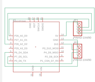
PCB Board
I made the PCB board in Fusion 360 based on what I set up on the breadboard. I connected all of the grounds together to create a stable connection, then I connected the 5v pin of the Xaio RP2040 to a 1k ohm resister and power of the LED that I will use to imitate the flashlight I used. I then used the footprints of header pins for the power supply cable adapter and connected it to the power and ground of the LED strip. I used a 1x6 header pin footprint for the sensor. I connected the 3v, SDA, SCL, and ground pins to their respective place on the Xiao RP2040. I used one last header pin footprint for the LED strip where i connected power to the power cable adapter and ground with all the others. I then connected the input pin of the LED strip to pin 6.
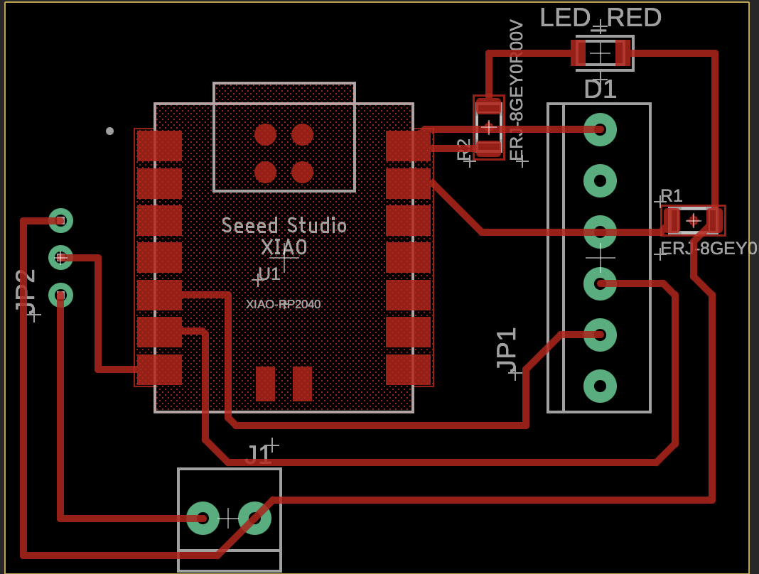
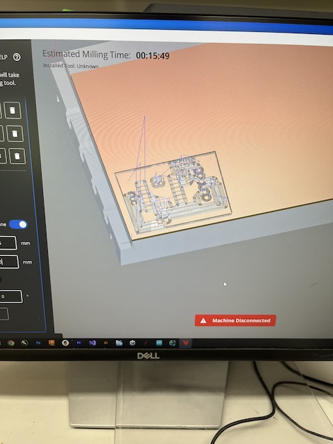
I then exported the zip file from fusion to the Bantom software. I selected a 1/64 inch flat endmill bit and set the trace clearance to 1.5 to make it easier to solder. I then generated the g-code and selected mill all files. After the machine finished milling, I used the vacuum and removed the dust and a putty knife to remove the board from the the machine and I started soldering. Final project file Zip and Trace PNG and Outline PNG
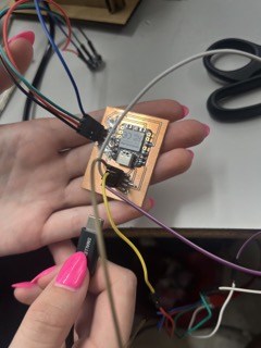
I gathered a Xiao RP2040, a high powered LED, a 1k ohm resiser, a 0 ohm resistor, 5 surface mount solder pins, and 6 female solder pins. I used insolated tape to tape the back of the Xiao RP2040. as well as the side of the board where I would solder the female headerpins. I then Stretched out the legs of the female header pins and soldered them to the board after using the insolated tape to insre there is no shorts, I Soldered that I moved on to the the 0 ohm resistor that I used to bridge a connection. I then soldered the 1k ohm resistor and the high powered LED. I then soldered the Xiao RP2040 and and plugged it in to make sure I light up and was not shorting. Once everything was soldered, I plugged everything in and tired to upload my code. For some reason the COM port would not show up and Arduino kept reading “not connected” when I looked for the board. No matter what I did, I could not get the Xioa to connect and I ultimatly ended up breaking a trcae. I re-milled and re-soldered a new board but this time before I soldered the Xiao, I plugged it into the computer first to make sure I would upload a code. After the code uploaded, I soldered the xiao and tested the board.
Troubleshooting color discrepencies
Even with the PCB board, the colors that the color sensor was reading were very inaccurate. I originally thought that the LEDs might have been showing the colors incorrectly, however, the RGB readings in the serial moniter also read very low values and inacurate colors. I looked at the adafruit website to see if I could possibly calibrate the sensor and get a more accurate reading. When looking at the website I noticed the most simple way to test the sensor is with a breadboard, arduino, and test code. Once I wired the circuit with an Arduino, I sent the ColorView test code and opened the serial moniter. unfortunatly, this continued to give weird reading. After discussion with the lab manager, we agreed that I should change the function of the sensor and use its proximity feature. I will now make it so that the light with change from green to yellow to red when you place and object on the shelf. This way I can keep the PCB Board I made and simply change the function.
Code
To find a code to work for this, I asked Claude AI for a code to generate an Arduino ide code that changes neopixels from off to purple based on proximity using the APDS9960 sensor and a Seeed Xiao rp2040 and he gave me this:
#include <Wire.h>
#include <SparkFun_APDS9960.h>
#include <Adafruit_NeoPixel.h>

#define NEOPIXEL_PIN 6  // Adjust this to the pin you've connected your NeoPixel strip to
#define NUM_PIXELS 16   // Adjust this to the number of NeoPixels in your strip

SparkFun_APDS9960 apds = SparkFun_APDS9960();
Adafruit_NeoPixel pixels = Adafruit_NeoPixel(NUM_PIXELS, NEOPIXEL_PIN, NEO_GRB + NEO_KHZ800);

void setup() {
  Serial.begin(115200);
  Wire.begin();

  if (apds.init()) {
    Serial.println("APDS-9960 initialization complete");
  } else {
    Serial.println("Something went wrong during APDS-9960 init!");
  }

  if (apds.enableProximitySensor(false)) {
    Serial.println("Proximity sensor is now running");
  } else {
    Serial.println("Something went wrong during proximity sensor init!");
  }

  pixels.begin();
  pixels.show(); // Initialize all pixels to 'off'
}

void loop() {
  uint8_t proximity_data = 0;

  if (!apds.readProximity(proximity_data)) {
    Serial.println("Error reading proximity data");
    return;
  }

  // Map the proximity data to LED brightness
  // Adjust these values based on your specific sensor readings and desired range
  int brightness = map(proximity_data, 0, 255, 0, 255);
  brightness = constrain(brightness, 0, 255);

  // Set all pixels to purple with the calculated brightness
  for(int i=0; i<NUM_PIXELS; i++) {
    pixels.setPixelColor(i, pixels.Color(brightness, 0, brightness)); // Purple color (R,G,B)
  }

  pixels.show();

  Serial.print("Proximity: ");
  Serial.print(proximity_data);
  Serial.print(" Brightness: ");
  Serial.println(brightness);

  delay(50); // Short delay to prevent overwhelming the sensor and serial output
}
I then uploaded this code to the to the PCB Board and moved my hand back and forth, this motion changed the color of the LEDs.
Final Assemnbly
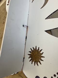
After I finished my electronics, I started to attatch the LEDs around the the shelf. During this I ran into a major problem, the silicon from the LEDs would not adhere to anything. I tried hot glue, super glue, and velcro but everything slipped off. I decided to change the type of LED I would be using back to simple neopixels. I hot glued the Neopixels all the way around the frame of the self. I realized I needed to make the hole for the sensor larger, so I used the laser cuter to make a 0.5in x 1 in square. After the square was cut, I placed the tabs in the self to the holes in the frame of the shelf. I then put the wires through the bottom part of the center hole for the tabs. After everything was assembled, I plugged in the Neopixels to the PCB Board, the C-cable and power cable to an out let and everything lit up. Here is the final video of the self working.
Presentation
Creative Common License

This work is licensed under a Creative Commons Attribution 4.0 International License.