9. Output devices
This week I was told to add an output device to a microcontroller board you’ve designed and document the process. I was also told to measure the power consumption of an output device as a group as seen on my group site
TinkerCAD testing
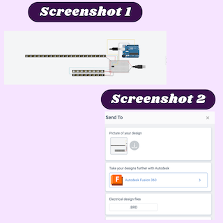
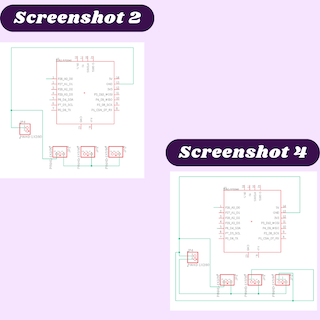
I wanted to first plan out how I wanted to wire this project in TinkerCAD before I moved to Eagle. I started with two strips of 8 neopixles for the sun and moon then a strip of 20 for the border. I knew I needed more than this, however, it was only for the schematic later on. I connected everything on a breadboard with an ATtiny412 chip. I started connecting by using a pinout for the ATtiny and connecting pin 6 to UDPI on the ATtiny. Next, I randomly chose pins 2, 3, and 7 for the output pins for the neopixles. Because I am connecting more than 8 neopixles, I would need an external power source to supply enough current to reach all of my neopixles. I used a USB cable in tinkerCAD to simulate the cable I would use for the external power source (screenshot 1). Once I had everything connected the way it should be I exported my schematic to EagleCAD (screenshot 2). link to TinkerCAD design
Eagle Designing
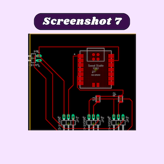
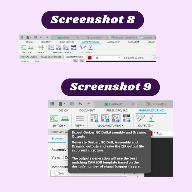
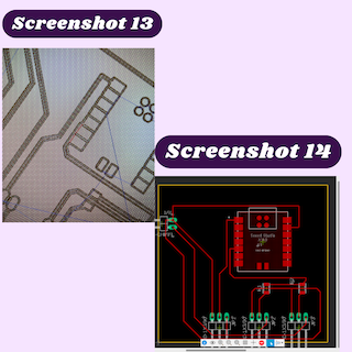
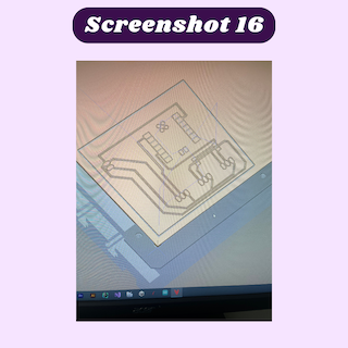
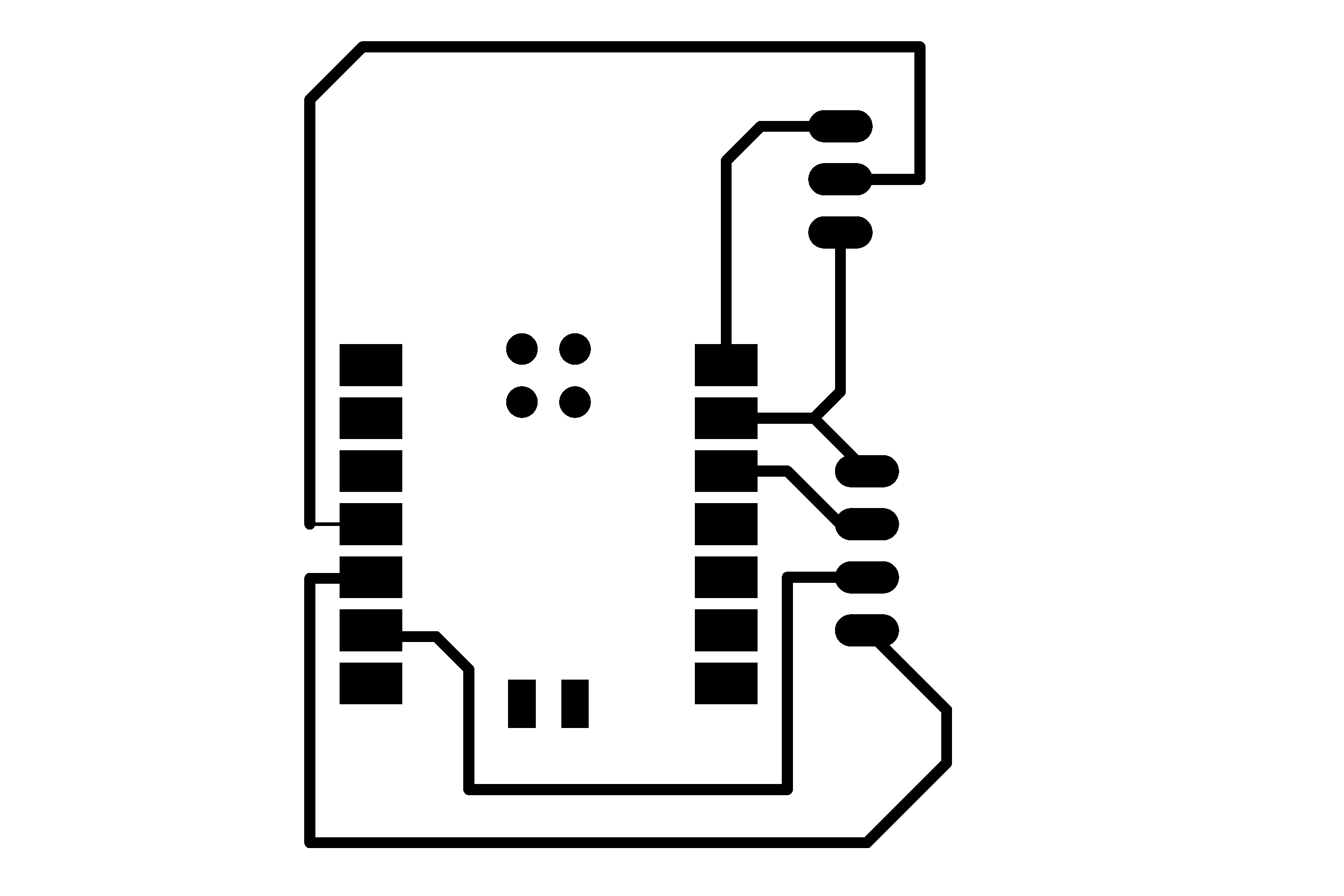
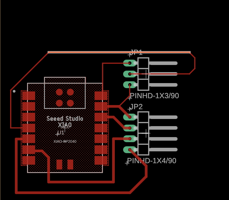
When I first imported my TinkerCAD design I looked it over and realized there were several things I needed to change including making the Arduino, neopixels, and USB into header pins. While I was changing out my electronics, I realized I could make this entire project easier by switching out the ATtiny chip I wanted to use for a Seeed Xiao RP2040 chip instead. That way I could eliminate the need for the Arduino and code it directly from the microcontroller. Because I needed to change so many things about the schematic, I decided to delete everything I had previously and create a new schematic. I started gathering all of the things that I would need from the libraries I had including neopixels, a Seeed Xiao RP2040 chip, and a USB. began wiring everything together, then I realized there was no need to have either a USB or neopixels in my schematic. I then replaced them all with header pins that would not only be easier to wire but also easier to solder and test with later on. Once I made that change in my design, I started with the ground and connected everything that needed a ground together (screenshot 3). From there I moved on to power. Because I am using an external power source, I used to power being supplied from there to power the neopixels and the Xiao RP2040 chip (screenshot 4). After the power was connected I needed to connect the output header pin I would be using for my neopixels. This is where I ran into a problem. The power and the ground connections that ran connected the middle two header pins were cutting off the output pin, so I could not connect the output pin to the chip I was using. I decided to combat this by using a 0 ohm resister to jump a connection and lead to the pin on the Xiao RP2040 chip (screenshot 5). I originally connected all of my neopixels to the same pin but I realized that because I wanted to use a different light pattern for one of the neopixel strips, I could not have then shared a pin. I kept the one group of header pins that did not require a 0 ohm resister separate and connected it to its pin on the chip. For the other two, I connected them together because they would be using the same code and put them on a different pin (screenshot 6). I then switched to the PCB editor to add the nets and change the board shape. I connected all the nets in a way that everything I needed would be connected (screenshot 7). I then exported my board as a Gerber file so that I could mill it out (screenshot 8 & 9). file

Milling- setup
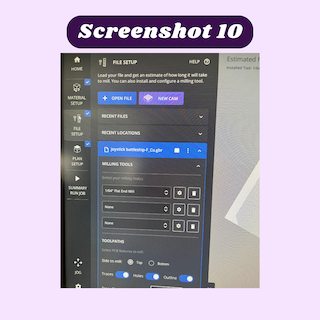
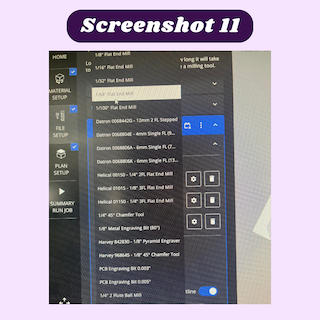
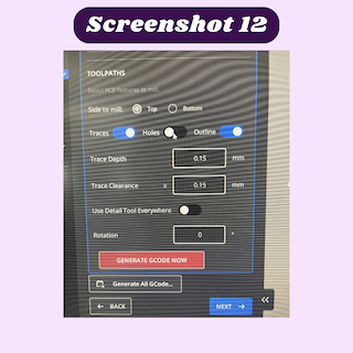
I then used the bantam software to mill out my board. I would normally start by installing the bit I wanted to use, however, the bit I wanted (1/64 endmill) was already installed in the machine. I then took a piece of Nitto tape and used it to secure the copper onto the bed. Once that was done I moved on to the files setup portion of milling (screenshot 10). I downloaded my file from the google drive folder that I uploaded it onto. From there I looked through the different layers it downloaded and selected the copper top and profile files and put them into the downloads folder. After that was done I followed the instructions the bantam software provided for milling a board. Because I already set up the bit and the material I jumped to uploading the files I wanted to mill. I deleted the project that someone else had on the board already and imported my files. From there I cleared the option for holes and changed the outline cut to the profile cut I downloaded from Eagle. Once all the settings I needed to change were changed, I looked at the bit that was selected to mill with. The program automatically selected a 1/32 bit, but that was not what I was using, so I changed the bit to a 1/64 flat endmill bit and clicked the next button (screenshot 11). The next part of the process was the offset. The offset was automatically set to 4mm for the x and y and 0mm for the Z axes (screenshot 1), but I was receiving an error message that said “Toolpath may cause the spindle to retract too far”. This error message confused me for a bit until I realized what exactly the plan offset was. This is where the bit will go to start milling the PCB board. I changed the offset manually with the command arrows to be in the corner of the copper. I also noticed red lines in places that were too small to be milled with a 1/64, so I needed to go back to my design and space out my traces. Once I did that I reimported my file, I looked over everything and there were no red lines or warnings, so once that was updated everything was ready to mill and I pressed the mill all button.


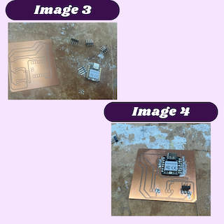
Soldering- Iteration 1
The first iteration I made had a Xiao RP2040 chip and 4 header pins. I soldered everything together, but I realized that I did not need to solder header pins onto the board. I should have instead soldered the positive and negative of the external power supply and the neopixles directly on the traces themselves. This way the soldering would look neater and I would not need to solder female header pins onto everything I wanted to connect.
Redesigning
At this point, I wanted to make my board more simplistic and focus on the output portion of the board without being dependent on the input part.
Wiring and Code testing
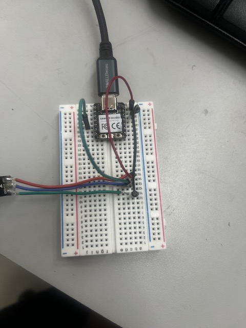
I started off testing with a Seeed Xiao RP2040 and a a breadboard. my setup looked like this
I then uploaded a test strand code that was pre installed from previous use in Arduino IDE without changes aside from the pin number, D3, I was left with this as a result:
// A basic everyday NeoPixel strip test program.

// NEOPIXEL BEST PRACTICES for most reliable operation:
// - Add 1000 uF CAPACITOR between NeoPixel strip's + and - connections.
// - MINIMIZE WIRING LENGTH between microcontroller board and first pixel.
// - NeoPixel strip's DATA-IN should pass through a 300-500 OHM RESISTOR.
// - AVOID connecting NeoPixels on a LIVE CIRCUIT. If you must, ALWAYS
//   connect GROUND (-) first, then +, then data.
// - When using a 3.3V microcontroller with a 5V-powered NeoPixel strip,
//   a LOGIC-LEVEL CONVERTER on the data line is STRONGLY RECOMMENDED.
// (Skipping these may work OK on your workbench but can fail in the field)

#include <Adafruit_NeoPixel.h>
#ifdef __AVR__
 #include <avr/power.h> // Required for 16 MHz Adafruit Trinket
#endif

// Which pin on the Arduino is connected to the NeoPixels?
// On a Trinket or Gemma we suggest changing this to 1:
#define LED_PIN    D3

// How many NeoPixels are attached to the Arduino?
#define LED_COUNT 6

// Declare our NeoPixel strip object:
Adafruit_NeoPixel strip(LED_COUNT, LED_PIN, NEO_GRB + NEO_KHZ800);
// Argument 1 = Number of pixels in NeoPixel strip
// Argument 2 = Arduino pin number (most are valid)
// Argument 3 = Pixel type flags, add together as needed:
//   NEO_KHZ800  800 KHz bitstream (most NeoPixel products w/WS2812 LEDs)
//   NEO_KHZ400  400 KHz (classic 'v1' (not v2) FLORA pixels, WS2811 drivers)
//   NEO_GRB     Pixels are wired for GRB bitstream (most NeoPixel products)
//   NEO_RGB     Pixels are wired for RGB bitstream (v1 FLORA pixels, not v2)
//   NEO_RGBW    Pixels are wired for RGBW bitstream (NeoPixel RGBW products)


// setup() function -- runs once at startup --------------------------------

void setup() {
  // These lines are specifically to support the Adafruit Trinket 5V 16 MHz.
  // Any other board, you can remove this part (but no harm leaving it):
#if defined(__AVR_ATtiny85__) && (F_CPU == 16000000)
  clock_prescale_set(clock_div_1);
#endif
  // END of Trinket-specific code.

  strip.begin();           // INITIALIZE NeoPixel strip object (REQUIRED)
  strip.show();            // Turn OFF all pixels ASAP
  strip.setBrightness(50); // Set BRIGHTNESS to about 1/5 (max = 255)
}


// loop() function -- runs repeatedly as long as board is on ---------------

void loop() {
  // Fill along the length of the strip in various colors...
  colorWipe(strip.Color(255,   0,   0), 50); // Red
  colorWipe(strip.Color(  0, 255,   0), 50); // Green
  colorWipe(strip.Color(  0,   0, 255), 50); // Blue

  // Do a theater marquee effect in various colors...
  theaterChase(strip.Color(127, 127, 127), 50); // White, half brightness
  theaterChase(strip.Color(127,   0,   0), 50); // Red, half brightness
  theaterChase(strip.Color(  0,   0, 127), 50); // Blue, half brightness

  rainbow(10);             // Flowing rainbow cycle along the whole strip
  theaterChaseRainbow(50); // Rainbow-enhanced theaterChase variant
}


// Some functions of our own for creating animated effects -----------------

// Fill strip pixels one after another with a color. Strip is NOT cleared
// first; anything there will be covered pixel by pixel. Pass in color
// (as a single 'packed' 32-bit value, which you can get by calling
// strip.Color(red, green, blue) as shown in the loop() function above),
// and a delay time (in milliseconds) between pixels.
void colorWipe(uint32_t color, int wait) {
  for(int i=0; i<strip.numPixels(); i++) { // For each pixel in strip...
    strip.setPixelColor(i, color);         //  Set pixel's color (in RAM)
    strip.show();                          //  Update strip to match
    delay(wait);                           //  Pause for a moment
  }
}

// Theater-marquee-style chasing lights. Pass in a color (32-bit value,
// a la strip.Color(r,g,b) as mentioned above), and a delay time (in ms)
// between frames.
void theaterChase(uint32_t color, int wait) {
  for(int a=0; a<10; a++) {  // Repeat 10 times...
    for(int b=0; b<3; b++) { //  'b' counts from 0 to 2...
      strip.clear();         //   Set all pixels in RAM to 0 (off)
      // 'c' counts up from 'b' to end of strip in steps of 3...
      for(int c=b; c<strip.numPixels(); c += 3) {
        strip.setPixelColor(c, color); // Set pixel 'c' to value 'color'
      }
      strip.show(); // Update strip with new contents
      delay(wait);  // Pause for a moment
    }
  }
}

// Rainbow cycle along whole strip. Pass delay time (in ms) between frames.
void rainbow(int wait) {
  // Hue of first pixel runs 5 complete loops through the color wheel.
  // Color wheel has a range of 65536 but it's OK if we roll over, so
  // just count from 0 to 5*65536. Adding 256 to firstPixelHue each time
  // means we'll make 5*65536/256 = 1280 passes through this loop:
  for(long firstPixelHue = 0; firstPixelHue < 5*65536; firstPixelHue += 256) {
    // strip.rainbow() can take a single argument (first pixel hue) or
    // optionally a few extras: number of rainbow repetitions (default 1),
    // saturation and value (brightness) (both 0-255, similar to the
    // ColorHSV() function, default 255), and a true/false flag for whether
    // to apply gamma correction to provide 'truer' colors (default true).
    strip.rainbow(firstPixelHue);
    // Above line is equivalent to:
    // strip.rainbow(firstPixelHue, 1, 255, 255, true);
    strip.show(); // Update strip with new contents
    delay(wait);  // Pause for a moment
  }
}

// Rainbow-enhanced theater marquee. Pass delay time (in ms) between frames.
void theaterChaseRainbow(int wait) {
  int firstPixelHue = 0;     // First pixel starts at red (hue 0)
  for(int a=0; a<30; a++) {  // Repeat 30 times...
    for(int b=0; b<3; b++) { //  'b' counts from 0 to 2...
      strip.clear();         //   Set all pixels in RAM to 0 (off)
      // 'c' counts up from 'b' to end of strip in increments of 3...
      for(int c=b; c<strip.numPixels(); c += 3) {
        // hue of pixel 'c' is offset by an amount to make one full
        // revolution of the color wheel (range 65536) along the length
        // of the strip (strip.numPixels() steps):
        int      hue   = firstPixelHue + c * 65536L / strip.numPixels();
        uint32_t color = strip.gamma32(strip.ColorHSV(hue)); // hue -> RGB
        strip.setPixelColor(c, color); // Set pixel 'c' to value 'color'
      }
      strip.show();                // Update strip with new contents
      delay(wait);                 // Pause for a moment
      firstPixelHue += 65536 / 90; // One cycle of color wheel over 90 frames
    }
  }
}
and it looked like this:
I wanted to take this a little further and change the RGB values to the color i wanted. I used this chart for purple RGB values so I would have a general idea of what the colors would look like.

I then changed the portion of the code where the RGB value were and I was left with this:
// NeoPixel Ring simple sketch (c) 2013 Shae Erisson
// Released under the GPLv3 license to match the rest of the
// Adafruit NeoPixel library

#include <Adafruit_NeoPixel.h>
#ifdef __AVR__
 #include <avr/power.h> // Required for 16 MHz Adafruit Trinket
#endif

// Which pin on the Arduino is connected to the NeoPixels?
#define PIN        D3 // On Trinket or Gemma, suggest changing this to 1

// How many NeoPixels are attached to the Arduino?
#define NUMPIXELS 6 // Popular NeoPixel ring size

// When setting up the NeoPixel library, we tell it how many pixels,
// and which pin to use to send signals. Note that for older NeoPixel
// strips you might need to change the third parameter -- see the
// strandtest example for more information on possible values.
Adafruit_NeoPixel pixels(NUMPIXELS, PIN, NEO_GRB + NEO_KHZ800);

#define DELAYVAL 300 // Time (in milliseconds) to pause between pixels

void setup() {
  // These lines are specifically to support the Adafruit Trinket 5V 16 MHz.
  // Any other board, you can remove this part (but no harm leaving it):
#if defined(__AVR_ATtiny85__) && (F_CPU == 16000000)
  clock_prescale_set(clock_div_1);
#endif
  // END of Trinket-specific code.

  pixels.begin(); // INITIALIZE NeoPixel strip object (REQUIRED)
}

void loop() {
  pixels.clear(); // Set all pixel colors to 'off'

  // The first NeoPixel in a strand is #0, second is 1, all the way up
  // to the count of pixels minus one.
  for(int i=0; i<NUMPIXELS; i++) { // For each pixel...

    // pixels.Color() takes RGB values, from 0,0,0 up to 255,255,255
    // Here we're using a moderately bright green color:
    pixels.setPixelColor(i, pixels.Color(235, 205, 255));

    pixels.show();   // Send the updated pixel colors to the hardware.

    delay(DELAYVAL); // Pause before next pass through loop
  }
}
The purple was not the color that I would like it to be, so i chose a deeper purple on the list and change the RGB vales again:
// NeoPixel Ring simple sketch (c) 2013 Shae Erisson
// Released under the GPLv3 license to match the rest of the
// Adafruit NeoPixel library

#include <Adafruit_NeoPixel.h>
#ifdef __AVR__
 #include <avr/power.h> // Required for 16 MHz Adafruit Trinket
#endif

// Which pin on the Arduino is connected to the NeoPixels?
#define PIN        D3 // On Trinket or Gemma, suggest changing this to 1

// How many NeoPixels are attached to the Arduino?
#define NUMPIXELS 6 // Popular NeoPixel ring size

// When setting up the NeoPixel library, we tell it how many pixels,
// and which pin to use to send signals. Note that for older NeoPixel
// strips you might need to change the third parameter -- see the
// strandtest example for more information on possible values.
Adafruit_NeoPixel pixels(NUMPIXELS, PIN, NEO_GRB + NEO_KHZ800);

#define DELAYVAL 300 // Time (in milliseconds) to pause between pixels

void setup() {
  // These lines are specifically to support the Adafruit Trinket 5V 16 MHz.
  // Any other board, you can remove this part (but no harm leaving it):
#if defined(__AVR_ATtiny85__) && (F_CPU == 16000000)
  clock_prescale_set(clock_div_1);
#endif
  // END of Trinket-specific code.

  pixels.begin(); // INITIALIZE NeoPixel strip object (REQUIRED)
}

void loop() {
  pixels.clear(); // Set all pixel colors to 'off'

  // The first NeoPixel in a strand is #0, second is 1, all the way up
  // to the count of pixels minus one.
  for(int i=0; i<NUMPIXELS; i++) { // For each pixel...

    // pixels.Color() takes RGB values, from 0,0,0 up to 255,255,255
    // Here we're using a moderately bright green color:
    pixels.setPixelColor(i, pixels.Color(119, 0, 200));

    pixels.show();   // Send the updated pixel colors to the hardware.

    delay(DELAYVAL); // Pause before next pass through loop
  }
}
After I achieved a purple that I liked, I wanted to change the pattern of the lights, so I looked into the code and saw where it told the neopixels to turn on and I changed the code by adding a few new lines telling it to change to a new color after flashing the first color. The final code looked like this:
// NeoPixel Ring simple sketch (c) 2013 Shae Erisson
// Released under the GPLv3 license to match the rest of the
// Adafruit NeoPixel library

#include <Adafruit_NeoPixel.h>
#ifdef __AVR__
 #include <avr/power.h> // Required for 16 MHz Adafruit Trinket
#endif

// Which pin on the Arduino is connected to the NeoPixels?
#define PIN        D3 // On Trinket or Gemma, suggest changing this to 1

// How many NeoPixels are attached to the Arduino?
#define NUMPIXELS 6 // Popular NeoPixel ring size

// When setting up the NeoPixel library, we tell it how many pixels,
// and which pin to use to send signals. Note that for older NeoPixel
// strips you might need to change the third parameter -- see the
// strandtest example for more information on possible values.
Adafruit_NeoPixel pixels(NUMPIXELS, PIN, NEO_GRB + NEO_KHZ800);

#define DELAYVAL 500 // Time (in milliseconds) to pause between pixels

void setup() {
  // These lines are specifically to support the Adafruit Trinket 5V 16 MHz.
  // Any other board, you can remove this part (but no harm leaving it):
#if defined(__AVR_ATtiny85__) && (F_CPU == 16000000)
  clock_prescale_set(clock_div_1);
#endif
  // END of Trinket-specific code.

  pixels.begin(); // INITIALIZE NeoPixel strip object (REQUIRED)
}

void loop() {
  pixels.clear(); // Set all pixel colors to 'off'

  // The first NeoPixel in a strand is #0, second is 1, all the way up
  // to the count of pixels minus one.
  for(int i=0; i<NUMPIXELS; i++) { // For each pixel...

    // pixels.Color() takes RGB values, from 0,0,0 up to 255,255,255
    // Here we're using a moderately bright green color:
    pixels.setPixelColor(i, pixels.Color(119, 0, 200));

    pixels.show();   // Send the updated pixel colors to the hardware.

    delay(DELAYVAL); // Pause before next pass through loop
      pixels.setPixelColor(i, pixels.Color(0, 0, 255));
       pixels.show();   // Send the updated pixel colors to the hardware.
 delay(DELAYVAL); // Pause before next pass through loop
  }
}
and the neopixels looked like this:
PCB board
I also needed to make a PCB for this week. I simply used the same design concept as the board I made previously this week. The slight changes I made was only having one set of 3 header pins and having the center pin connected to D3 on the xiao. This board would also be used for my final project so I added a place for my color sensor that I connected to power, ground, SDA, and SCL pins to transmit and recieve data. Gerber file and Traces png and outline PNG
milled/ soldered board
here is my milled and soldered bored that I made using the same process as in week 6

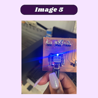
testing
To test my board, I simply used female to female header pins to connect the neopixels to the board and uploaded a code i found from the adafruit website where they gave instructions for using the color sensor. Before uploading the code I changed the board in the aurdino software to tyhe Xiao RP2040 and I updated the com port to 11. After uploading, I used different pieces of colored paper and help them up to the sensor and watched the LEDs change color.
#include <Wire.h>
#include "Adafruit_TCS34725.h"

// Pick analog outputs, for the UNO these three work well
// use ~560  ohm resistor between Red & Blue, ~1K for green (its brighter)
#define redpin A1
#define greenpin A0
#define bluepin A2
// for a common anode LED, connect the common pin to +5V
// for common cathode, connect the common to ground

// set to false if using a common cathode LED
#define commonAnode true

// our RGB -> eye-recognized gamma color
byte gammatable[256];


Adafruit_TCS34725 tcs = Adafruit_TCS34725(TCS34725_INTEGRATIONTIME_50MS, TCS34725_GAIN_4X);

void setup() {
  Serial.begin(9600);
  //Serial.println("Color View Test!");

  if (tcs.begin()) {
    //Serial.println("Found sensor");
  } else {
    Serial.println("No TCS34725 found ... check your connections");
    while (1); // halt!
  }

  // use these three pins to drive an LED
#if defined(ARDUINO_ARCH_ESP32)
  ledcAttachPin(redpin, 1);
  ledcSetup(1, 12000, 8);
  ledcAttachPin(greenpin, 2);
  ledcSetup(2, 12000, 8);
  ledcAttachPin(bluepin, 3);
  ledcSetup(3, 12000, 8);
#else
  pinMode(redpin, OUTPUT);
  pinMode(greenpin, OUTPUT);
  pinMode(bluepin, OUTPUT);
#endif

  // thanks PhilB for this gamma table!
  // it helps convert RGB colors to what humans see
  for (int i=0; i<256; i++) {
    float x = i;
    x /= 255;
    x = pow(x, 2.5);
    x *= 255;

    if (commonAnode) {
      gammatable[i] = 255 - x;
    } else {
      gammatable[i] = x;
    }
    //Serial.println(gammatable[i]);
  }
}

// The commented out code in loop is example of getRawData with clear value.
// Processing example colorview.pde can work with this kind of data too, but It requires manual conversion to
// [0-255] RGB value. You can still uncomments parts of colorview.pde and play with clear value.
void loop() {
  float red, green, blue;

  tcs.setInterrupt(false);  // turn on LED

  delay(60);  // takes 50ms to read

  tcs.getRGB(&red, &green, &blue);

  tcs.setInterrupt(true);  // turn off LED

  Serial.print("R:\t"); Serial.print(int(red));
  Serial.print("\tG:\t"); Serial.print(int(green));
  Serial.print("\tB:\t"); Serial.print(int(blue));

//  Serial.print("\t");
//  Serial.print((int)red, HEX); Serial.print((int)green, HEX); Serial.print((int)blue, HEX);
  Serial.print("\n");

//  uint16_t red, green, blue, clear;
//
//  tcs.setInterrupt(false);  // turn on LED
//
//  delay(60);  // takes 50ms to read
//
//  tcs.getRawData(&red, &green, &blue, &clear);
//
//  tcs.setInterrupt(true);  // turn off LED
//
//  Serial.print("C:\t"); Serial.print(int(clear));
//  Serial.print("R:\t"); Serial.print(int(red));
//  Serial.print("\tG:\t"); Serial.print(int(green));
//  Serial.print("\tB:\t"); Serial.print(int(blue));
//  Serial.println();

#if defined(ARDUINO_ARCH_ESP32)
  ledcWrite(1, gammatable[(int)red]);
  ledcWrite(2, gammatable[(int)green]);
  ledcWrite(3, gammatable[(int)blue]);
#else
  analogWrite(redpin, gammatable[(int)red]);
  analogWrite(greenpin, gammatable[(int)green]);
  analogWrite(bluepin, gammatable[(int)blue]);
#endif
}
Power consumption
I looked at the Adafruit website to understand how neopixels use the current they are supplied with. All neopixels are able to run off of 5V and each individual neopixel uses 60 mA of current to light up all 3 colors. According to the site, the equation to calculate the amount of current needed for the entire strip is #NeoPixels × 60 mA ÷ 1,000 = min amps. For my final project, I will need this equation so I can know what type of power source I will need.
Reflection
I learned a lot about understanding how neopixels use current and how I will need to take that into consideration when I am powering my neopixels for my final project. I was also able to see how different RGB values appear through the neopixels and that I will need to chose a darker color than I want so that it will actually show to the correct color.