0.5. Pre-Fab
During this period of time, I learn some basic skills like KiCad, board milling, surface mount soldering, etc that I would later need during Fab Academy.
Surface Mount Soldering:
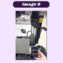
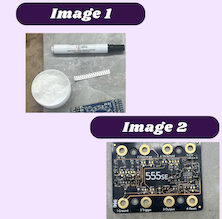
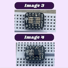
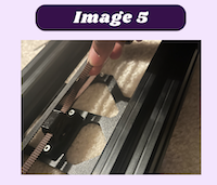
One of the first pre-fab things I learned was surface mount soldering. Knowing how to surface mount solder is very important because, with projects where small components are necessary, you can make your electronics as small as necessary. The first thing we learned was the importance of flux (image 1). Flux is used to help clean the surface of what you will be soldering. The technique I chose to use was taking a white flux paste and dipping my solder wire in it. on a practice board, I would melt a little bit of solder onto the pad that I planned to solder on. From there I used tweezers to hold down the component I needed to solder and melt the solder on the pad so that the component would stick. I then soldered the other parts of the components to hold them in place. Learning this process was pretty simple. In the rare case, I did get a solder bridge, all I had to do to resolve this problem was run the soldering iron over the bridge to remove the solder. I continued practicing this skill by creating a 555 timer with surface mount components (image 2). I also soldered a 412 chip that I later used for other projects (images 3 & 4).
555 Timers:
To truly understand what a 555 Timer is, I viewed this slide show I watched this video, which explained the inner workings of 555 timers. The 8 pins in a 555 Timer are ground, trigger, output, reset, control voltage, threshold, discharge, and Vcc/ power. using the knowledge I gained from the video, I used the 555 Timer as a flip flop to blink an LED. With a 555 Timer, switch LED, 9V battery, polarized and non-polarized capacitor, a 330-ohm resistor, and 2-10k resistor, I used a test Tinkercad circuit as a model for the build with buttons. From there I needed to build the circuit without the buttons. I connected the power and ground wires to the power rail of the breadboard. I then connected the ground pin from the 555 timer to the ground rail and the Vcc pin to power. From there I used the 2-10k resistors to connect Vcc to discharge and discharge to the threshold. I also used a red wire to supply power to the Vcc pin of the 555 Timer. I then connected the polarized capacitor to the ground and threshold. I also used a wire to connect the threshold to the trigger as well as connect the non-polarized capacitor to the ground and control. From there I used a 330-ohm resistor to connect the output and the cathode of the LED while also connecting the anode of the LED to the ground. Finally, I connected power to the reset, completing the build.
KiCad:
I followed a series of Tech Exploration tutorials to learn how to use KiCad to create PCB boards and schematics. After making the board I used the Bantam CNC machines to mill my board.
Milling:
Using this workflow I took the PCB board I designed in KiCad and milled using the Bantam software and CNC machine.
3D printer assembly:
Before the beginning of Fab Academy, everyone in my lab participating was tasked with assembling a Pursa Mini+ 3D printer. For me, this was a very exciting challenge because I love assembling things like this. It was projected that the total assembly would take about a week, but I completed my printer in 3 days. The first step I completed was counting and identifying all of the components I needed. From there, by following the assembly guide, I began building my 3D printer.
Starting with the YZ-axis assembly, I paid very close attention to the directions and followed them step by step to avoid complications later on. One of the things I had trouble with during this step was making sure that the Y-belt was positioned correctly and tightened adequately. I looked at one of the pre-built Pura Minis that we have in our lab and noticed the tension and positioning they had and I adjusted the belt on my printer to match theirs (image 5).
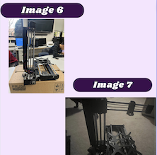
The next step was building the X-axis & extruder assembly (images 6 & 7). This was a fairly simple step but assembling and mounting the extruder was difficult for me because later on, I realized that somewhere along the way I messed it up. I realized I had made a mistake on this part while loading my filament. My filament would not catch and load into my machine even after I cut the tip of it at a diagonal angle. To resolve this I took the extruder off of the Y-axis and disassembled it. From there I noticed I had not screwed a screw in tight enough, so the spring in the extruder was loose. After tightening the screw I put the extruder back in its original position. I then tried again to load my filament and it worked with no problems.
Assembly of the print head and heat bed were next (image 8). The only part of this step that was truly challenging was installing some of the parts with only two hands. At times I would have to hold 3+ components together all the while using a hex key to screw them together. Also positioning the wires in a way that will not damage the wires was challenging.

From there I needed to attach the LCD and other electronics. When screwing in the LCD I had to use extreme force, but it was difficult to use just the hex key, so I turned the hex key horizontally and used pliers to turn the screw. After I had adequately screwed the LCD in, I moved on with the rest of the instructions. I also ran into a huge problem with consolidating all of my wires and electronics into the box they were intended to go into. I tried several times to gently stuff all the remaining wire and screw all the components together, but I could not get everything to stay without getting damaged. Unsure of how to resolve this, I brought my printer in and let one of my friends Ginny Foster take a look at it. She then held down all of my parts and I then screwed them in.
The next and easiest step was putting together the spool holder. All this step required was gathering the necessary parts and 8 screws. First I took 2 of the base spool holders and placed an M3n nut inside them. From there I took the bearings and inserted them into the appropriate spots. After that, I took the remaining two base spool holders and placed them on top of the first two with the bearings. using an M3x12 screw I secured all the bases to the spool holder. I then took the rails and put them in the slots made for them. Afterward,s I took slid the other half of the base and put it onto the rails as well. I then secured it with more M3x12 screws. That completed the assembly for the spool holder.
To finalize my Prusa, I simply adjusted the sensor height and placed the bed on the printer. From there I connected it to a power source and followed the instructions that were displayed on the LCD screen (image 9).