WEEK 010
ON THIS PAGE WE WILL FIND A BRIEF DESCRIPTION OF MY JOB THROUGHOUT THE TENTH WEEK
GENERALITIES
This week I will take another small step to learn about PCBs. This week consists of testing an electronic board with some devices, in my case I will use a motor, the Nema 17 as output. In order to use the motor, first I am going to make a PCB that can support it and at the end I connect the Nema to program the ESP 32 microprocessor. It will be quite a challenge, since I would never have imagined achieving this goal.
I have thought about doing this practice because the nema 17 are going to be the motors that I will use in my final project.
| Day | Wenesday | Thursday | Friday | Saturday | Sunday | Monday | Tuesday |
|---|---|---|---|---|---|---|---|
| 09:00 | |||||||
| 10:00 | Meeting CT | Assigments | Assigments | Local Review | |||
| 11:00 | Meeting CT | Assigments | Assigments | Local Review | |||
| 12:00 | Assigments | Assigments | |||||
| 13:00 | Assigments | Assigments | Regional Review | ||||
| 14:00 | Assigments | Assigments | Regional Review | ||||
| 15:00 | Fabacademy | Practice | write Documents | ||||
| 16:00 | Fabacademy | Practice | write Documents | Review Documents | |||
| 17:00 | Fabacademy | Practice | Assigments | write Documents | Review Documents | ||
| 18:00 | Fabacademy | Practice | Assigments | write Documents | Review Documents | ||
| 19:00 | Practice | Assigments | write Documents | Review Documents | |||
| 20:00 | |||||||
| 21:00 | Tutorial | Tutorial | Assigments | write Documents | |||
| 22:00 | Tutorial | Tutorial | Assigments | write Documents | Write Documents | ||
| 23:00 | Tutorial | Tutorial | write Documents | Write Documents | |||
| 24:00 | Tutorial | Tutorial | write Documents | ||||
| 01:00 | |||||||
| 02:00 |
In this practice the objective is to continue with the learning of the programming and manufacture of the electronic boards built by myself. There are several things to learn at the same time.
MAKING THE PCB
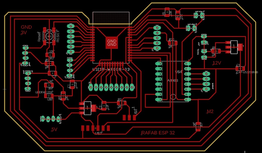
The first step is to design the electronic board in Eagle, as I did in the previous weeks.
Not everything is design. There are more important things like understanding how it works. My instructors Gustavo and Hector tell me that it is advisable to build a plate that has multiple outlets. That is why I am going to attach a connector to all the outputs of the ESP 32. In this way I will be able to couple different output devices at the same time.
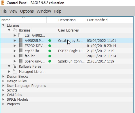
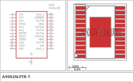
Since I am going to use an engine, the appropriate component must be integrated into the eagle software. I'm going to download the A4982 SLPTRT and then upload it to the library. I'm going to leave the library link by clicking Here.
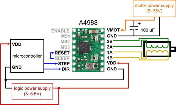
In the image above you can see the operation of the driver and which pins are necessary for its operation.
Here I leave the address to search for the files I have seen by clicking Here.
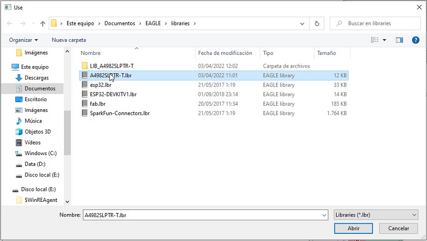
Once we have selected the components that are going to make up the PCB, we will have to install them in the board design software. To do this, I'm going to repeat the steps I've done in the previous week. I leave a brief list of steps to follow and their corresponding images.
- Step one, search the internet for Eagle libraries.
- Step two, I go to Library in the store menu and look for library manager.
- Step three in the "available" section I load the libraries that I am going to use.
First I download the libraries from the internet
I go to Library in the store menu and look for library manager
In the menu and the available section I look for the library
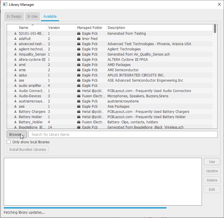
I check that the library is green.
All set, I can continue with my work
To make my board, I will use the esp32 as a microprocessor. The goal is to learn more about this device. I think I'm going to use it on my PCB for my final project and I like the idea of knowing it.
Among the characteristics that most make me think of using this microprocessor, are the following.
- The ESP-WROOM-32 is a powerful module that integrates WiFi and Bluetooth. In my smart lamp I would like to use Bluetooth to communicate with it.
- The ESP-WROOM-32 module works at 3.3V in power supply, pin inputs and outputs, so it should NOT be powered with 5V. It is recommended to place a 100uF capacitor in parallel with the power supply to filter current spikes. The input/output pins (GPIO) work at 3.3V, so for connection to 5V systems it is necessary to use level converters such as: 3.3-5V level converter.
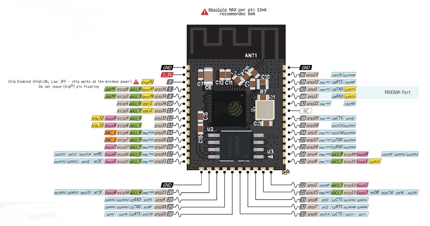
For more information about pinout, clicking Here.
For more information about datasheet, clicking Here.
For more information about webpage, clicking Here.
For more information about Wiki, clicking Here.
DESIGNING THE PCB WITH ESP 32
The design idea of this PCB was to have many pins and thus be able to introduce inputs and outputs on the same card.
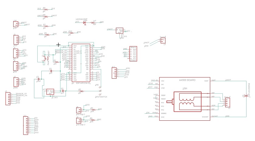
For the realization of this scheme I had to use 5 jumpers since there were many lines that were impossible to join.
To be able to work with esp in arduino it will be necessary to carry out a series of previous works. I leave a link where I found some instructions.
For more information about Wiki, clicking Here.
After having finished the design of the plate I will manufacture it.
For the realization of the board we have had to wait for the ESP32 Microprocessor. It hangs up due to gasoline has delayed the delivery 15 days, so now to work hard.
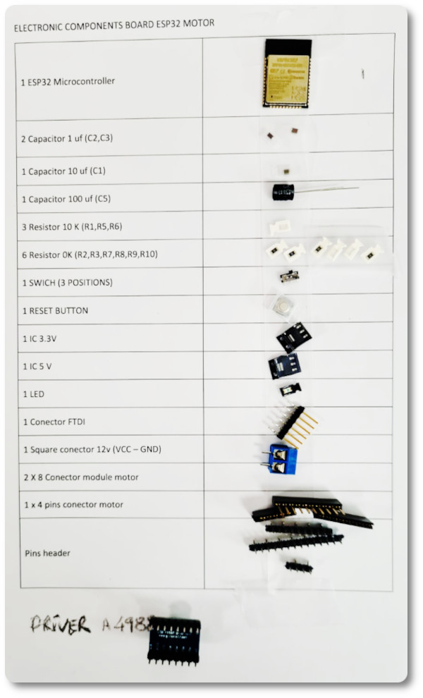
After having searched for the necessary components I am going to carry out.
The board the first time I prepare such a large pcb and many components require me to modify them before putting them in.
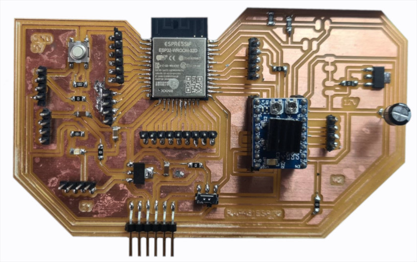
Just need to test it :), to see if everything works as it should.
SOFTWARE PROGRAMMING
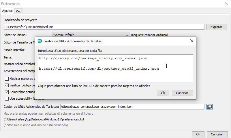
For the programming of the board, I have used Arduino. Before using it you have to make some changes in the software.
 Uploading microchip firmware to Arduino
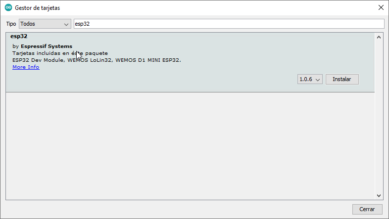
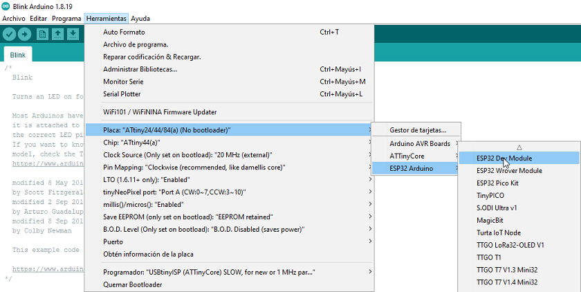
The first thing to add is the ESP32 processor components. The Arduino is an open source program but intended for Arduino boards. To be able to use it with our cards, you have to add the components.
Another preliminary step is to find out if the microprocessor pins and circuit outputs match. We will do this with the pinpout above.
 Checking the microprocessor pins
In our case, it is like this. We will not have any problem in programming.
 Verification of the installed microchip
We check, whether it recognizes the port where the programmer is connected.
 Uploading the "Button" program to the board
We verify that the programmer is the right one.
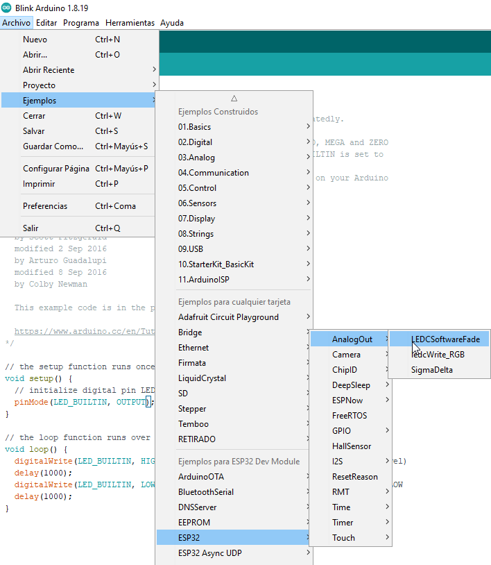
From the basic examples system we load the program for the button and burn it into the fabricated board.
 Uploading the "Button" program to the board
Everything works properly.
CHECK THE RESULTS ON MY BOARD
here I leave some verification videos.
To check if the board works I have put a blue power LED.
Now I'm going to pass the programming of the LED.
I'm going to test the motor as well.
Everything works great
GROUP ASSIGNMENT
I am going to measure the voltage of the outputs.
Checked!!!!
CONCLUSIONS OF THE WEEK
It has been one more step to learn about the manufacture of electronic boards and their programming. It is getting more and more complicated but learning is very nice.
I was searching the internet for programming on motors and lights. There is a lot of stuff. It must be said that the ESP32 works a little differently and you have to be careful.
“What went wrong”: The ESP32 because of the gas oil problem arrived 2 weeks late. I was praying and scared that it would arrive on time.
It is a week where you can learn many things about PCB and programming. she is very pretty.
“What went well”: My soldering on PCBs is getting a lot better.
“What will you do differently next time?”: Review the material available with much more time.
MY FILES
Here I am uploading the files that I have been making this week


