WEEK 012
ON THIS PAGE WE WILL FIND A BRIEF DESCRIPTION OF MY JOB THROUGHOUT THE TWELFTH WEEK
GENERALITIES
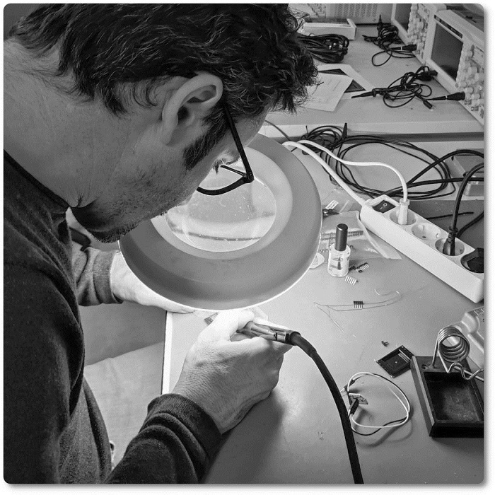
Another week to learn more about PCBs. This week I am going to use the same electronic board made for week 10. When I made this board, I did it with the aim of doing the practices on "Input" and "Output". Although I will make it again, the one before I tried it I broke it. After doing it I will try some devices that are closer to my final project. On this board I have placed an ESP32 Microprocessor with Wi-Fi input, to this I will also add a light sensor and a voice sensor.
The sensors will be coupled to the nema 17 motors that I will use in my final project.
| Day | Wenesday | Thursday | Friday | Saturday | Sunday | Monday | Tuesday |
|---|---|---|---|---|---|---|---|
| 09:00 | |||||||
| 10:00 | Meeting CT | Assigments | Assigments | Local Review | |||
| 11:00 | Meeting CT | Assigments | Assigments | Local Review | |||
| 12:00 | Assigments | Assigments | |||||
| 13:00 | Assigments | Assigments | Regional Review | ||||
| 14:00 | Assigments | Assigments | Regional Review | ||||
| 15:00 | Fabacademy | Practice | write Documents | ||||
| 16:00 | Fabacademy | Practice | write Documents | Review Documents | |||
| 17:00 | Fabacademy | Practice | Assigments | write Documents | Review Documents | ||
| 18:00 | Fabacademy | Practice | Assigments | write Documents | Review Documents | ||
| 19:00 | Practice | Assigments | write Documents | Review Documents | |||
| 20:00 | |||||||
| 21:00 | Assigments | write Documents | |||||
| 22:00 | Assigments | write Documents | Write Documents | ||||
| 23:00 | write Documents | Write Documents | |||||
| 24:00 | Tutorial | Tutorial | write Documents | ||||
| 01:00 | |||||||
| 02:00 |
In this practice the objective, apart from the weekly objective, is to continue learning the programming and manufacturing of the electronic boards built by myself. There are several things to learn and of course it is important to repeat to go deeper.
REFABISHING THE PCB WITH IMPROVEMENTS
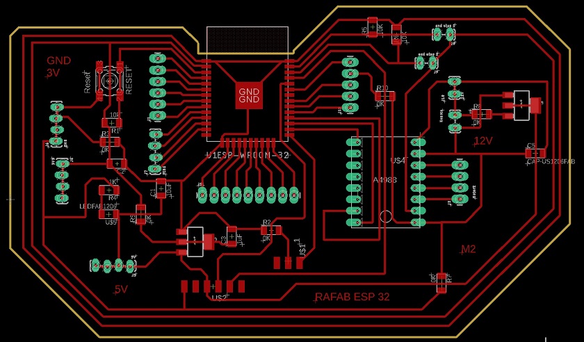
In week 10, the PCB layout was done. For ease of work, the Eagle software was used.
Design is important but there are more important things. My instructors Gustavo and Héctor told me that it was advisable to build a platter that has multiple connectors to the microprocessor to couple different inputs and outputs. That is why I am going to put a connector to all the outputs of the ESP 32. In this way I will be able to use inputs and outputs at the same time.
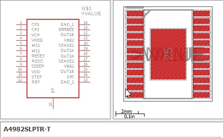
In my final project, the light sensors and sensors, bluethouth and voice are going to power the NEMA 17 motors, which need the DRIVERS A4982 SLPTRT and then I will upload it to the library. I'm going to leave the library link by clicking Here.
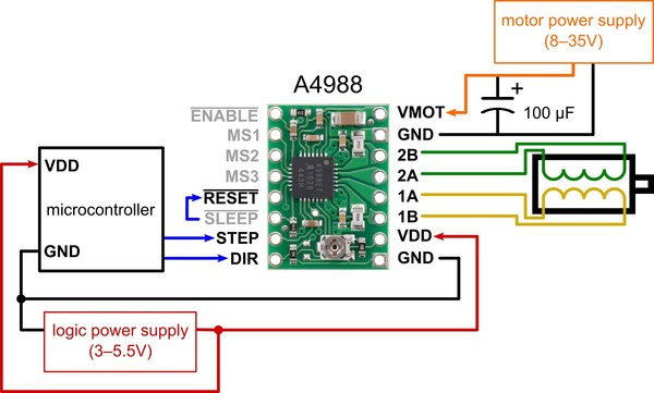
In the image above you can see the operation of the driver and which pins are necessary for its operation.
Here I leave the address to search for the files I have seen by clicking Here.
Once we have selected the components that are going to make up the PCB, we will have to install them in the board design software. To do this, I'm going to repeat the steps I've done in the previous week. I leave a brief list of steps to follow and their corresponding images.
- Step one, search the internet for Eagle libraries.
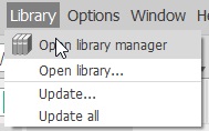
- Step two, I go to Library in the store menu and look for library manager.
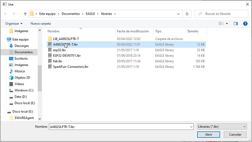
- Step three in the "available" section I load the libraries that I am going to use.
First I download the libraries from the internet
I go to Library in the store menu and look for library manager
In the menu and the available section I look for the library
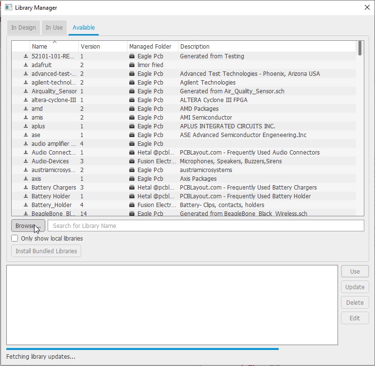
I check that the library is green.
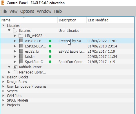
All set, I can continue with my work
To make my board, I will use the esp32 as a microprocessor. The goal is to learn more about this device. I think I'm going to use it on my PCB for my final project and I like the idea of knowing it.
Among the characteristics that most make me think of using this microprocessor, are the following.
- The ESP-WROOM-32 is a powerful module that integrates WiFi and Bluetooth. In my smart lamp I will use Bluetooth to communicate with it.
- The ESP-WROOM-32 module works at 3.3V in power supply, pin inputs and outputs, so it should NOT be powered with 5V. It is recommended to place a 100uF capacitor in parallel with the power supply to filter current spikes. The input/output pins (GPIO) work at 3.3V, so for connection to 5V systems it is necessary to use level converters such as: 3.3-5V level converter.
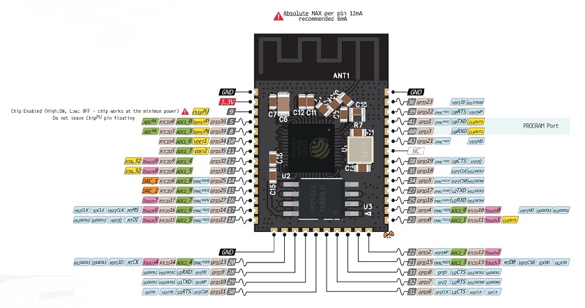
For more information about pinout, clicking Here.
For more information about datasheet, clicking Here.
For more information about webpage, clicking Here.
For more information about Wiki, clicking Here.
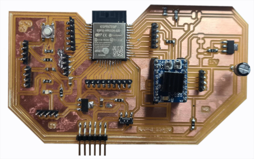
DESIGNING THE PCB WITH ESP 32
The design idea of this PCB was to have many pins and thus be able to introduce inputs and outputs on the same card.
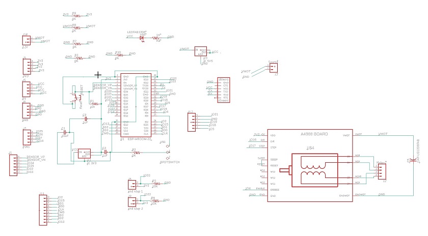
For the realization of this scheme I had to use 5 jumpers since there were many lines that were impossible to join.
To be able to work with esp in arduino it will be necessary to carry out a series of previous works. I leave a link where I found some instructions.
For more information about Wiki, clicking Here.
After having finished the design of the plate I will manufacture it.
For the realization of the board we have had to wait for the ESP32 Microprocessor. It hangs up due to gasoline has delayed the delivery 15 days, so now to work hard.
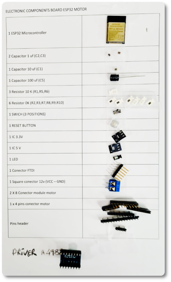
After having searched for the necessary components I am going to carry out.
Some connectors on the board were not in stock. I made minor modifications to fit them together.
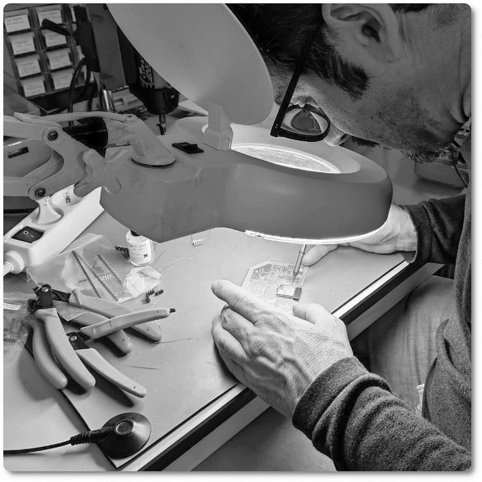
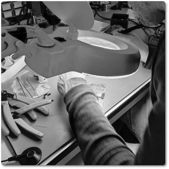
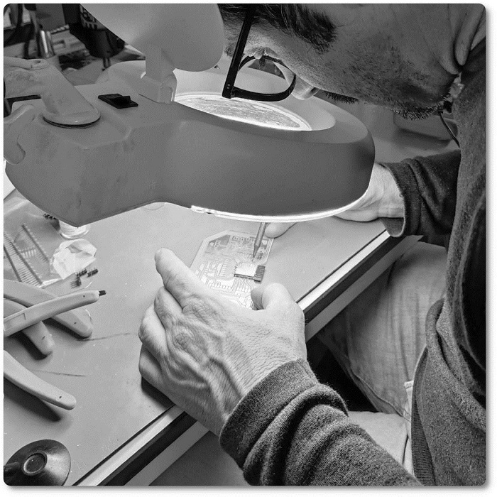
Just need to test it :), to see if everything works as it should.
SENSOR PT15 (FOTOTRANSISTOR)
As in my final project, I am going to adopt a phototransistor, I think it is convenient to try with it and understand its programming. The fact of manufacturing a PCB and a light detection system does not guarantee success, so I will test myself and my instructors :)...
There are two versions of this phototransistor, the PT15 21B and the PT15 21C. I chose the PT15 21B.
The 21B works in the invisible IR range, while the 21C works in the visible range.
For more information about PT15-21B, clicking Here.
For more information about PT15-21C, clicking Here.
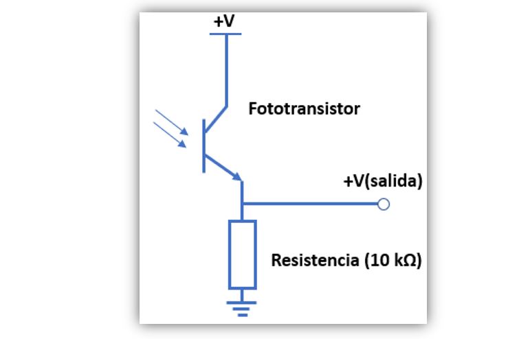
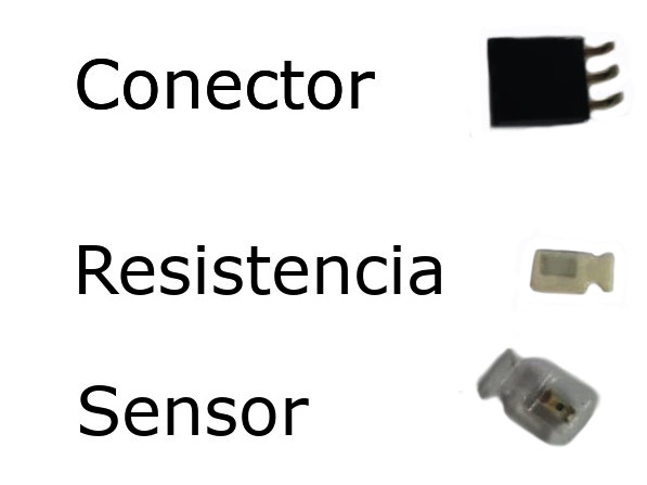
To connect the phototransistor to the board I will need to make the schematic in the image, a 10K resistor will be needed. The emitter is directly connected to VCC and will be powered by it. The collector to the resistor and this node to the signal. The other side of the resistor to GND. I leave the schematic below.
The scheme to be carried out in Eagle is in the following image.
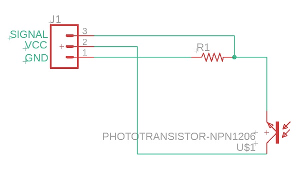
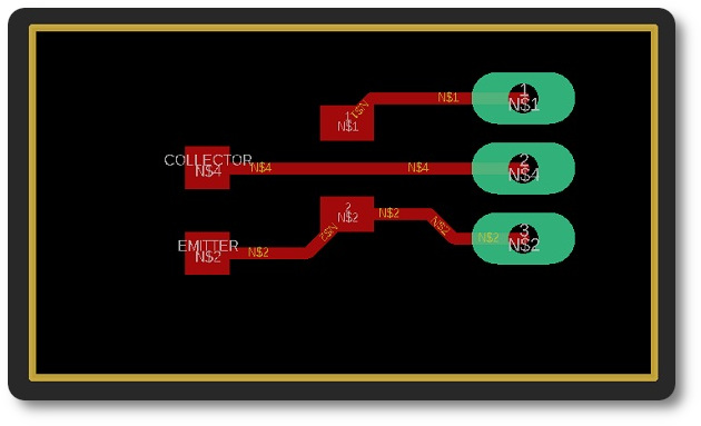
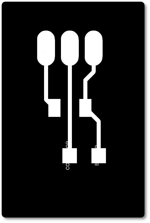
As always from Eagle export two images to work on Mods.

It's tiny!!!!!!!!!
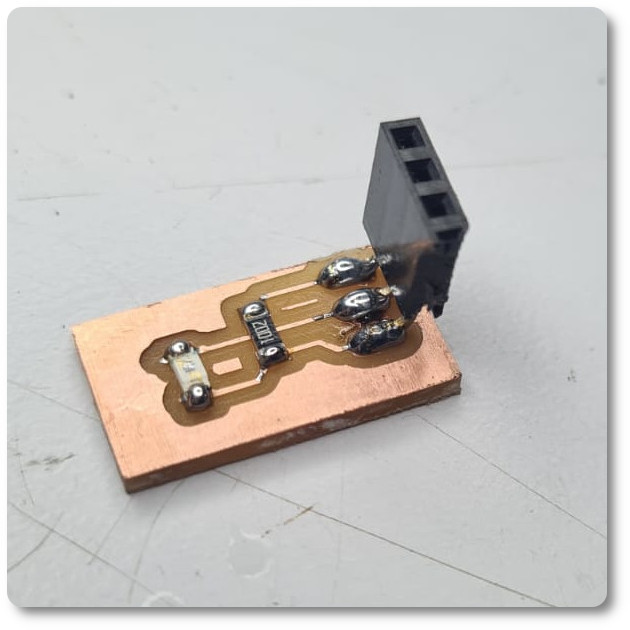
Component schematic.
To the montage!!!!!!!
Voice sensor or microphone
Like the previous one in my final project adopt a microphone. I will take the opportunity to understand its operation and programming.
There are several types of microphones, in my case I have tried two, one with an amplifier and one without. The one with the amplifier has a much better reading. The one that does not have an amplifier, although it works very well, is not sensitive and I like it less.
The first micropone was: KY-038
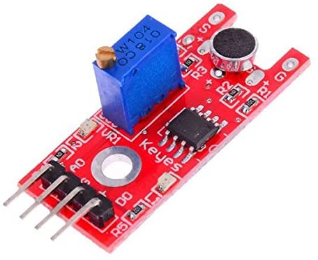
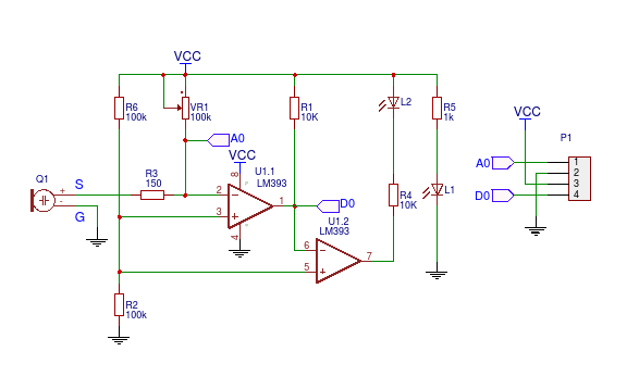
If we wanted to make a KY-038 microphone we should operate this scheme.
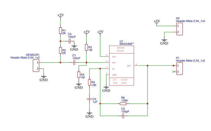
The second micropone that I test was: MAX4466
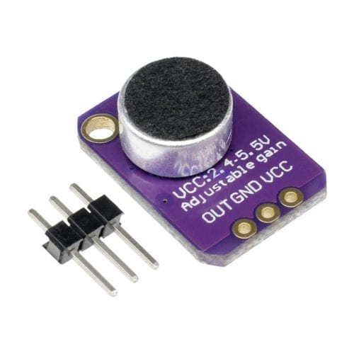
For more information about MAX4466, clicking Here.
If we wanted to make a KY-038 microphone we should operate this scheme.
PROGRAMMING SENSOR PT15
I will work with Arduino IDE. In case you need to download:
For more information Arduino ID, clicking Here.
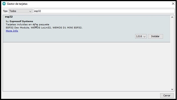
First of all, I need to install the libraries for the microcontroller.
For more information esp32, clicking Here.
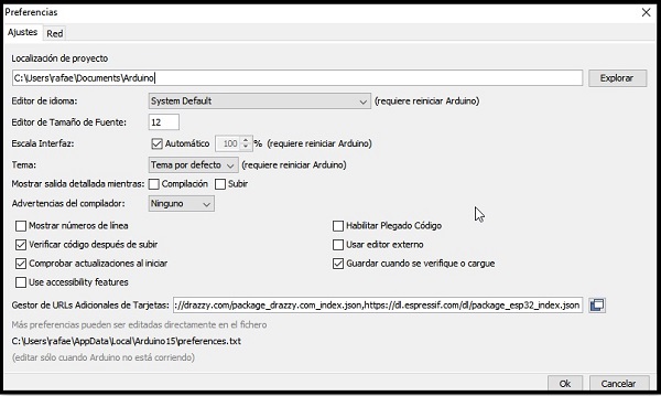
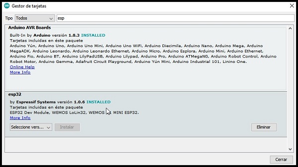
Find the ESP32 and install it.
Configure Board Manager:
Find the ESP32 and install it.
installed.
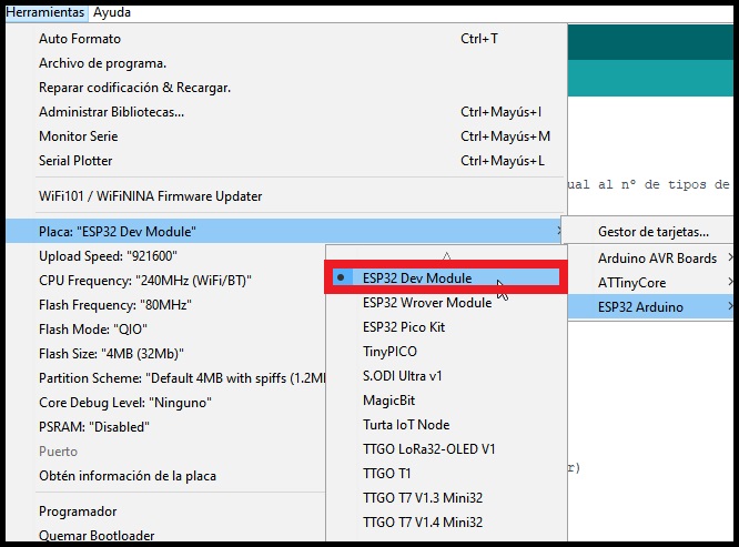
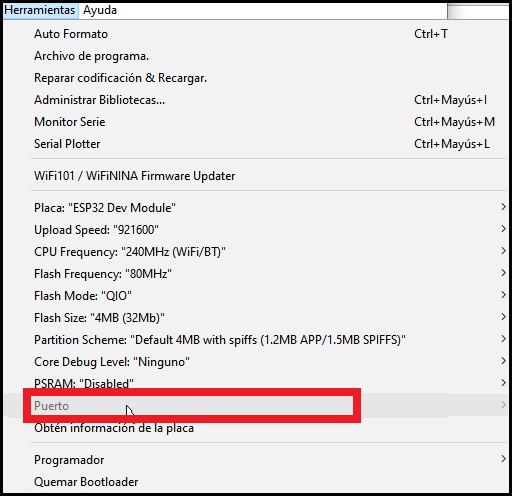
1. Select your board in Tools > board
2. Select the port that will appear by default in the tab
Programming the test
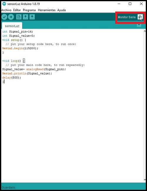
I am going to compile the programming language to carry out the test and check that everything works correctly.
- int Signal_pin=14;
- int Signal_value=0;
- void setup() {
- // put your setup code here, to run once:
- Serial.begin(115200);
- {
- void loop() {
- // put your main code here, to run repeatedly:
- Signal_value= analogRead(Signal_pin);
- Serial.println(Signal_value);
- delay(500);
- }
I am going to use an Arduino tool to measure the sensitivity of the sensor. To this end, the Arduino IDE software monitor itself can read me.
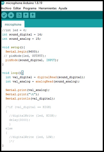
PROGRAMMING MICROPONE KY-038 AND MAX4466
Unlike the previous programming, I already have the Arduino ready, so I just need to insert the programming and test.
- int sound_digital = 14;
- int sound_analog = 15;
- void setup() {
- // pinMode(led, OUTPUT);
- pinMode(sound_digital,INPUT);
- {
- void loop() {
- int val_digital = digitalRead(sound_digital);
- int val_analog = analogRead(sound_analog);
- Serial.print(val_analog);
- Serial.print("\t");
- Serial.print(val_digital);
Here I leave a screenshot in Arduino
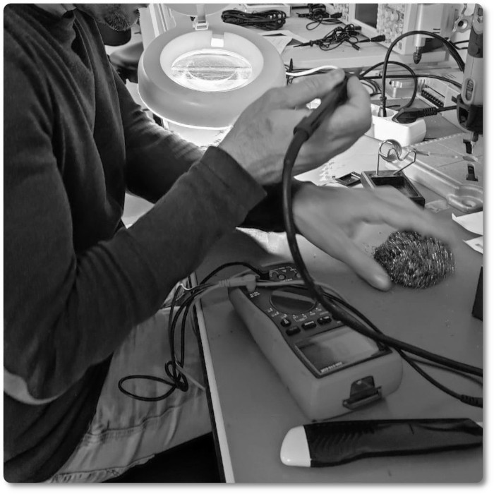
TESTS
Two tests have been developed, one on a light photosensor and the other on a voice detection module.
The first test has been carried out with the photosensor manufactured and the ESP 32 plate.
We start with the configuration ESP 32 for Arduino:
Well, here I leave the tests carried out with the KY-038 microphone:
And here I leave the tests carried out with the max4466 microphone:
CONCLUSIONS OF THE WEEK
A week where I can improve my electronic board manufacturing skills
Everything has seemed too concentrated to me, it's cool to try and the trial and error method is the only one that resolves doubts and helps to understand things.
I love that you can work things out and think it's just the beginning.
“What went wrong”: The time, the time. Everything runs very fast.
“What went well”: It's a fascinating world, I think there are cases where technology can save human lives.
“What will you do differently next time?”: I would make it mandatory, first to program with arduino and accessories and then to manufacture. It is much more useful.
MY FILES
Here I am uploading the files that I have been making this week


