WEEK 07
ON THIS PAGE WE WILL FIND A BRIEF DESCRIPTION OF MY JOB THROUGHOUT THE SEVEN WEEK
GENERALITIES
This week we have worked with large milling machines. The goal is to understand how milling machines work by exploring their possibilities. As an architect I was very attracted to the possibility of making something related to furniture. It will be because in the course of our training, we have always been watching the development of the BAUHAUS. The architects who studied at that school have always been manufacturing in laboratories.
| Day | Wenesday | Thursday | Friday | Saturday | Sunday | Monday | Tuesday |
|---|---|---|---|---|---|---|---|
| 09:00 | |||||||
| 10:00 | Meeting CT | Assigments | Assigments | Local Review | |||
| 11:00 | Meeting CT | Assigments | Assigments | Local Review | |||
| 12:00 | Assigments | Assigments | |||||
| 13:00 | Assigments | Assigments | Regional Review | ||||
| 14:00 | Assigments | Assigments | Regional Review | ||||
| 15:00 | Fabacademy | Practice | Practice | write Documents | |||
| 16:00 | Fabacademy | Practice | Practice | write Documents | Review Documents | ||
| 17:00 | Fabacademy | Practice | Practice | Assigments | write Documents | Review Documents | |
| 18:00 | Fabacademy | Practice | Practice | Assigments | write Documents | Review Documents | |
| 19:00 | Practice | Practice | Assigments | write Documents | Review Documents | ||
| 20:00 | |||||||
| 21:00 | Tutorial | Tutorial | Assigments | write Documents | |||
| 22:00 | Tutorial | Tutorial | Assigments | write Documents | Write Documents | ||
| 23:00 | Tutorial | Tutorial | write Documents | Write Documents | |||
| 24:00 | Tutorial | Tutorial | write Documents | ||||
| 01:00 | |||||||
| 02:00 |
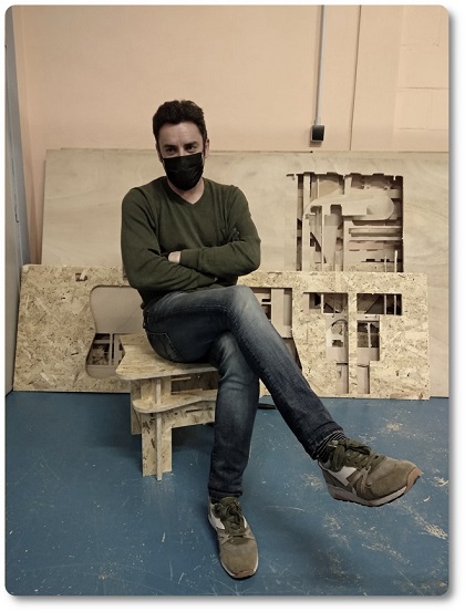
I have never used large format milling, but I love the possibility of seeing the result of a job done by myself. I would like, even if it were a simple job, that it had some added possibility. I've been thinking of a piece of furniture that would have more possibilities. I am going to try to make a chair that can be easily transported.
DESIGNING A CHAIR
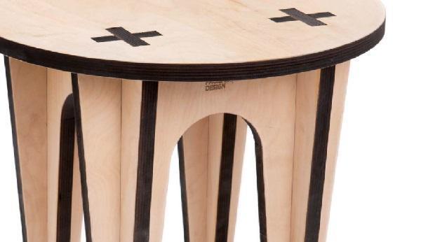
To carry out the task, the first step that I have followed has been the study of the files of the weekly repository. So i look for more information on the internet. As there is a lot of information on the internet, I have seen some types of knots that could be adapted to my case very easily. In particular, there is one page that I really liked. You can see some furniture that inspired me by clicking HERE.
In particular, there is a knot that I really liked. I see it very safe and it seems to work very well in my case. The production of this furniture is by Mario Pagliaro and the effect is very amazing.
After having obtained the inspiration for the design of the furniture that I wanted to manufacture, I only had to establish a series of requirements that my artifact would have.
- That the wood could be used well
- That it was truly safe
- Intuitive assembly
- Transportable
After having understood very well what I was going to make, I went to the drawing software to start making the chair.
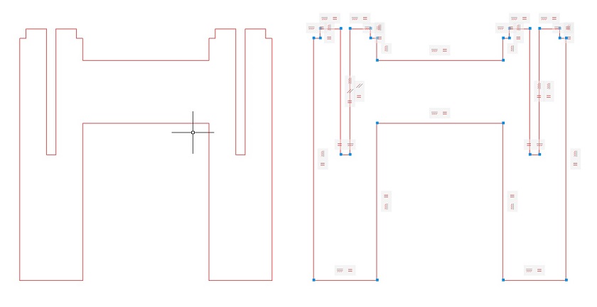
To obtain a good result and to be able to modify the design instantly. I made a parametric drawing, in the figure on the left you can see the profile of the chair while on the right the geometric and dimension restrictions.
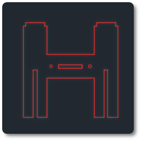
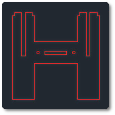
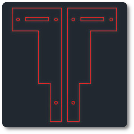
Above, the planes of the lateral profiles, the seat, the backing and a reinforcement structure have been placed.
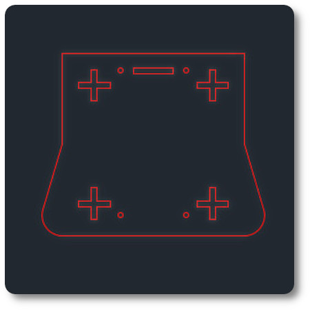
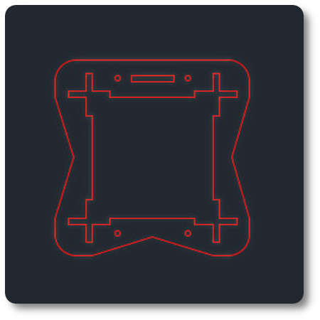
In the views below, I have made a 3D model of the structure assembled and coupled for transport.
CREATING THE CODE FOR THE MILLING MACHINE
To perform the milling after having done the parametric drawing and three-dimensional modeling, I'm going to download Vetric's Aspire software.
If you want to download it, you just need to click HERE.
It is logical that to make the file for milling, several steps have to be carried out.
After you have downloaded, installed and opened the program.
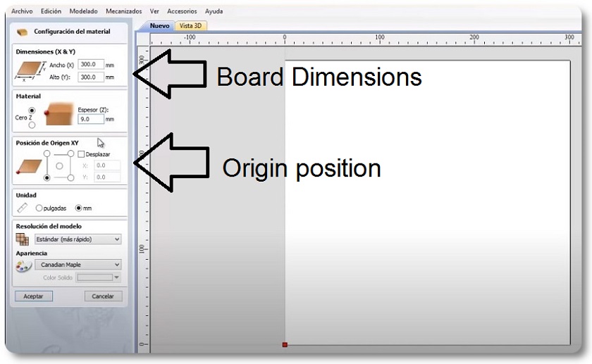
Step 1: Set the dimensions of the wooden board.
Step 2: Then, as I created it with Autocad, I click on import and open it as .DXF, after having imported it I got an error, the file had drawings on the second layer that I had to delete. Clean and import again.
Step 3: Now it is very important to place the drawings and the board at the origin. We will do this with the origin button "posición de origen XY"in the left panel.
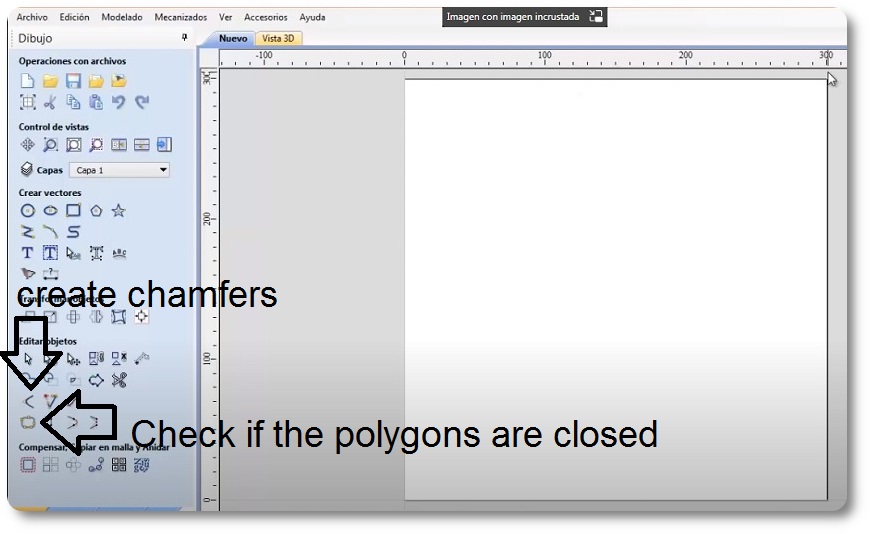
Step 4: Another important step is to verify that the figures are closed polygons. The software has a command that automatically analyzes and closes them, "check open vectors and with this tool close them".
Step 5: Another step is to add the chamfers in some corner. Not all the corners need them, only where the angles are interior and the proca is unable to leave them challenges. This would lead to a manufacturing problem.
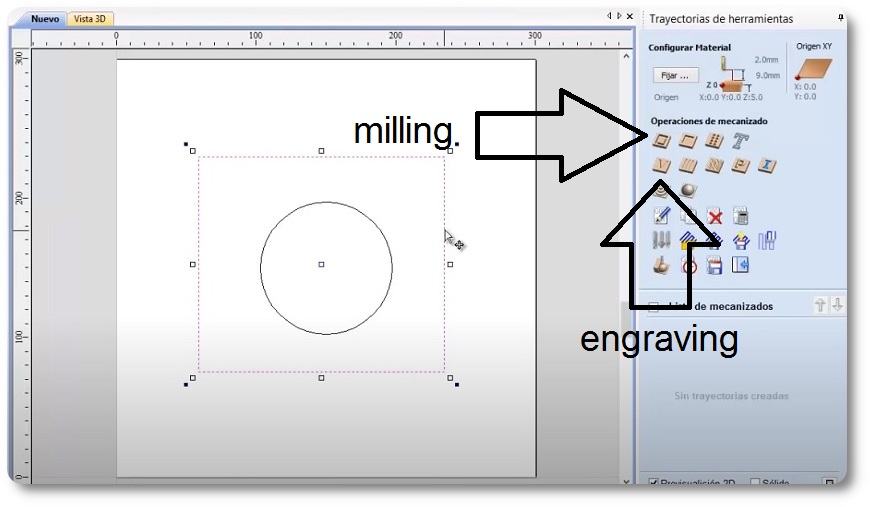
Step 6: Another fundamental step is to choose the type of machining. In my case it is a milling and this is chosen in the menu on the right in the first button.
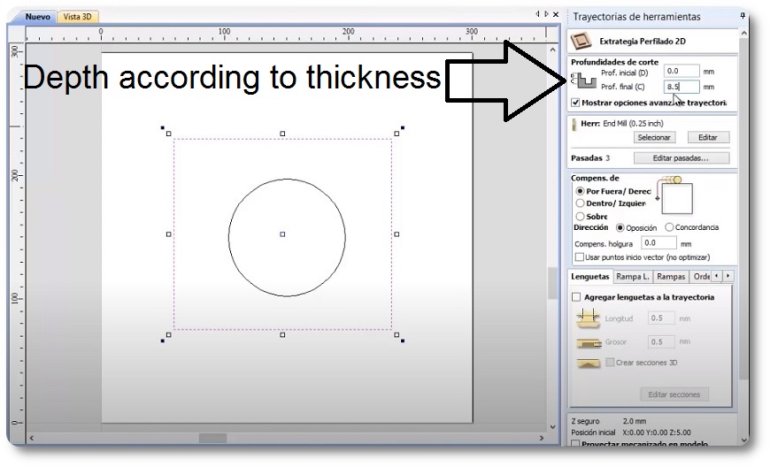
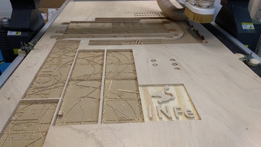
Step 7: Once I have reviewed and adapted the design to the machine I will start with the milling parameters. In my case the board is 15 mm thick, I am going to make a milling with a depth of 18 mm. I am going to use a different depth (I add 3 mm depth, in a photo below you can see the tracks or marks left by previous work) to ensure that the pieces separate when milling with the machine. To do this, below the panel that I am going to mill I have placed another lost board of wood.
Step 8: After having created the milling track, I am going to make the clamps, the internal cuts of the figures would allow the pieces to move and could damage the drawing.
Step 9: Another fundamental step is to choose the type of machining. In my case it is a milling and this is chosen in the menu on the right in the first button.
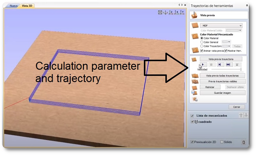
Step 10: So that the machine does not break the board, I am going to indicate that it starts with a ramp approach and I give it to calculate.
Step 11: I notice that all the milling appears in blue in the image simulating the trajectory.
Step 12: To finish I save the file in “G code Arcs (mm) .tap” format.
choice of wood
For my work I am going to use oriented strand board
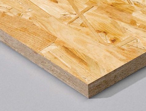
OSB boards or oriented strand boards (English: oriented strand board) are boards formed by successive layers of chips of several centimeters, where each layer is pressed with the chips oriented in the same direction, and the layers are joined, as than with plywood panels, perpendicularly to achieve greater stability and resistance, which makes them an alternative to solid wood in many areas.
During the manufacturing process of osb boards, different types of wood can be used, the most common being pine and fir (fast-growing species), poplar being one of the most common in quality osb boards, and also different types of adhesives or glues. Depending on the materials used, the characteristics of the OSB boards may be different. They are commonly classified into 4 groups, with OSB-3 being the one that has been standardized from the point of view of consumption:
- OSB-1: Interior use, basically furniture. It is the most basic range and its commercialization is currently very limited.
- OSB-2: Load applications in dry environments.
- OSB-3: Load-bearing applications in relatively humid environments. It is the most common type of OSB board today and the one with the best value for money.
- OSB-4: High load performance in relatively humid environments.
In terms of measurements, since it is marketed in a board format, it conforms to industry standards. The most common size is 244×120 centimeters. The most common thickness is 15mm, but we can easily find it between 10mm and 40mm.
Advantages and characteristics of osb 3 boards:
- A comparatively lower price. In comparison, the price of OSB 3 would be approximately one third of solid wood and half of plywood.
- Great resistance to breaking and torsion.
- Absence of knots, which facilitates machining and cutting.
- Greater use of forestry, so its manufacture has less impact on the environment. On the other hand, it is not necessary to use specific species, and even fast-growing or even small trees can be used.
- Reciclaje muy sencillo.
- No suele ser atacado por insectos.
Perhaps the biggest drawback of this type of board is that in the face of adverse humidity conditions and without the corresponding treatment, they deform to a greater extent than plywood. It is also worth mentioning that it is somewhat heavier and slightly less rigid. Although on the other hand the resistance is practically the same at all points. In plywood boards this does not happen if two nodes of the different veneers coincide in the same place. At these points the resistance is significantly reduced, well below that of an OSB.
MILLING THE CHAIRK
After having built and edited the file with Aspire (milling machine software). I save the file on a flash drive to insert into the router control knob and turn on the router.
The first step to follow is to establish a zero point in XYZ, which we will call HOME. Any 3D machine needs to set a HOME.
On the Sedicup CT machine, home plate is positioned in the lower left corner.
To do this, I bring the cutter to the corner of the corresponding wooden board, carefully make x = 0 y = 0 and slowly go down until I make z = 0, my machine has a tool that detects when it makes contact with the cutter the zero of Z.
Then I'll go to the router and set the speed parameters. My instructors advise me to use 7000 rpm.
Then I look for the file and I give it to start.
When the machine has started, I turn on the wood chip extractor and wait.
 Milling machine before laying the board
The milling machine has a lost board so that the milling cutter can go down without damaging the machine.
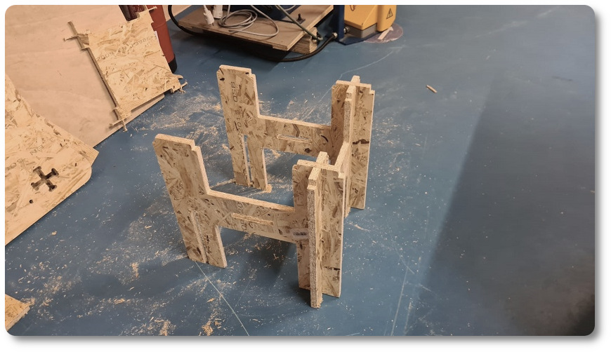
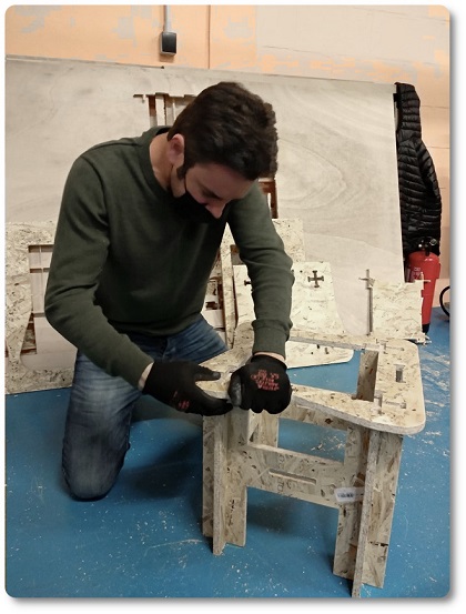
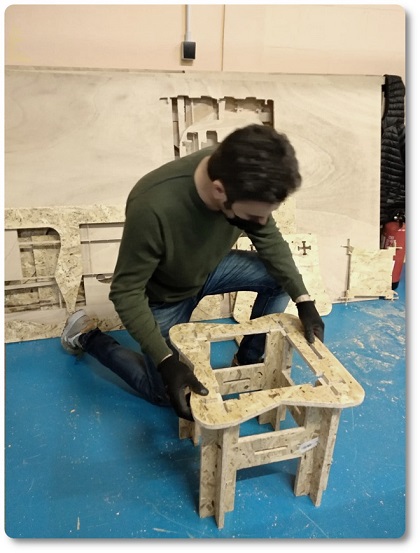
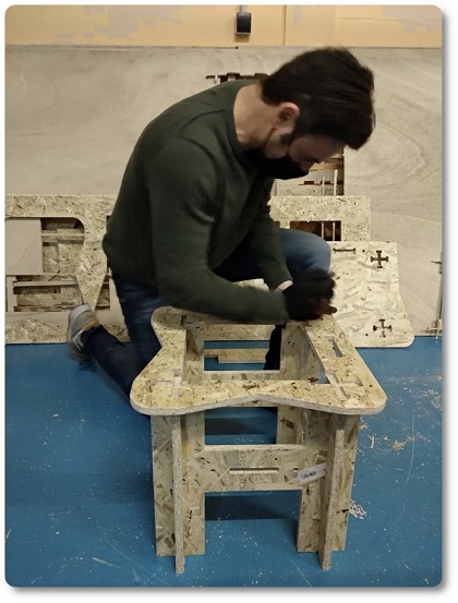
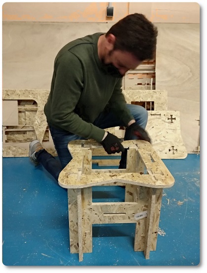
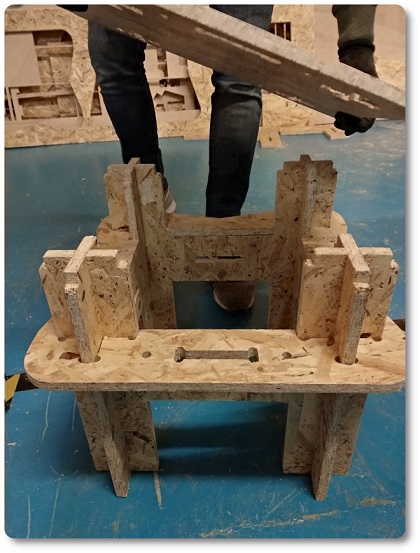
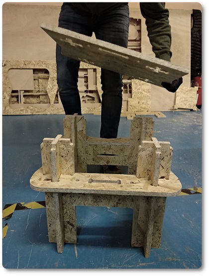
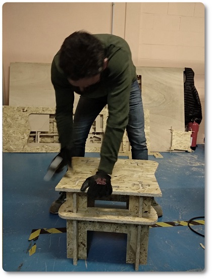
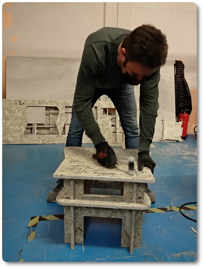
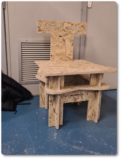
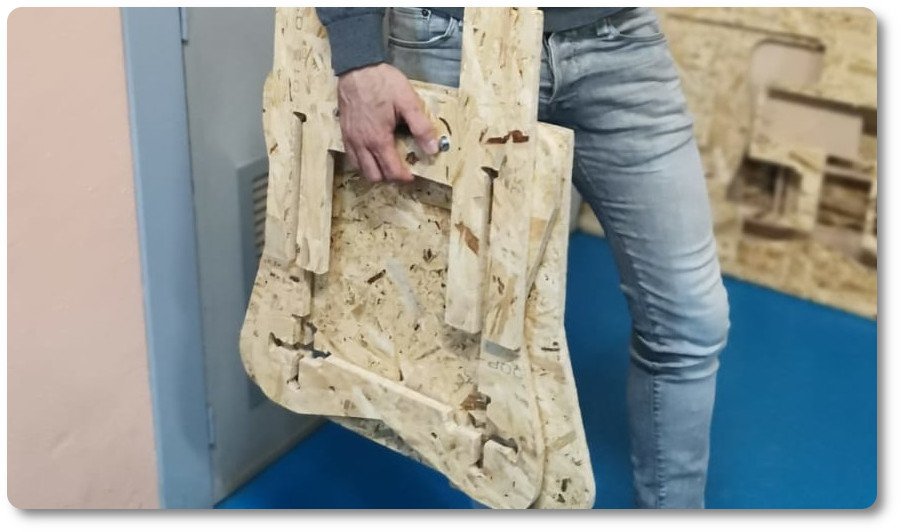
ASSEMBLING
Once we have milled all the pieces, it only remains to assemble them. It is a chair that does not need screws and glue. It is assembled and disassembled cold.
CONCLUSIONS OF THE WEEK
I have really enjoyed working with the milling machine. I have always worked with the pantograph and never with the milling machine. With this machine you can do a lot of things very well done.
I really liked the documentation on the internet about furniture with cold knots.
“What went wrong”: I didn't like putting the circles so that the piece would fit. I like that they are challenges even if you have to finish them by hand.
It is a week where you can learn many things about milled boards.
“What went well”: I liked a lot of what I have made. It would be spectacular to be able to choose suitable wood for this type of machine.
“What will you do differently next time?”: Choose wooden betas. The curving of the milling on the betas has to be spectacular.
MY FILES
Here I am uploading the files that I have been making this week


