WEEK 11
ON THIS PAGE WE WILL FIND A BRIEF DESCRIPTION OF MY JOB THROUGHOUT THE ELEVENTH WEEK
GENERALITIES
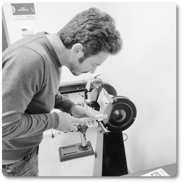
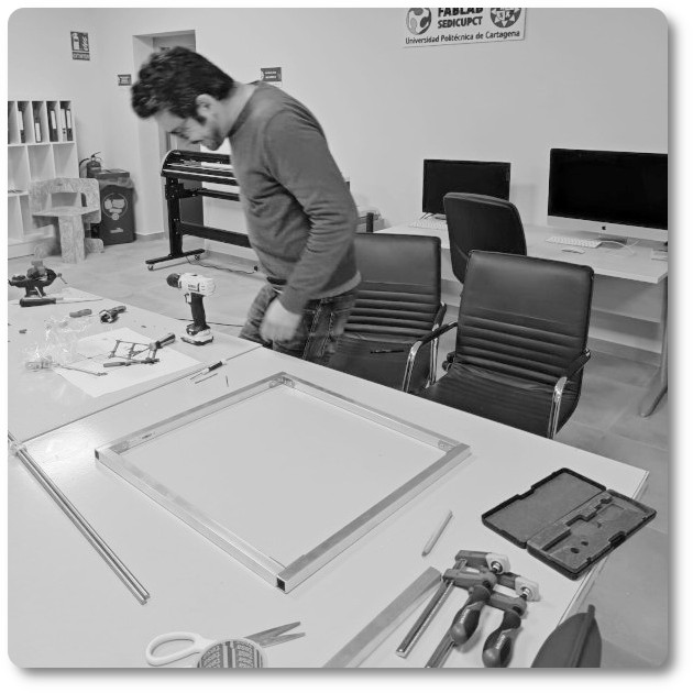
This week I am going to work to learn from the bottom how CNC machines work. I am going to take advantage of this week on the design and manufacture of a machine to understand each of the parts that make up an automatic machine. I believe that once I have learned one, the others work in a similar way.
I have always had a desire to achieve machines that can be installed on site. My training is an architect and I believe that since laptops, tablets and mobile phones are already essential tools in a work, machines must also start to be there.
My Instructor, Lola Ojadas proposed to me to make a hot wire machine to cut polystyrene. I thought it was a very interesting idea. I'll make a walking hotwire trimmer. That it can be moved on site and that it can be checked right there if the repeated product is suitable to be able to continue manufacturing and not have to travel numerous times for verification.
In order to achieve this, I first need an example that I managed to help understand how it works and then modify the parts and make it portable. In general, from what I have understood, hot wire machines have an indispensable role in a manufacturing laboratory, but very limited to specific needs. For these reasons, it would be opportune to design one that can be assembled and disassembled in a short time to occupy the space when needed.
THE PROGRAM
I will try to do the best I can even though I am alone and there are many things that have to be done, to achieve this I will have to work hard and daily. There will be a way to rest later.
METHODOLOGY
The flow of the work methodology has been as follows:
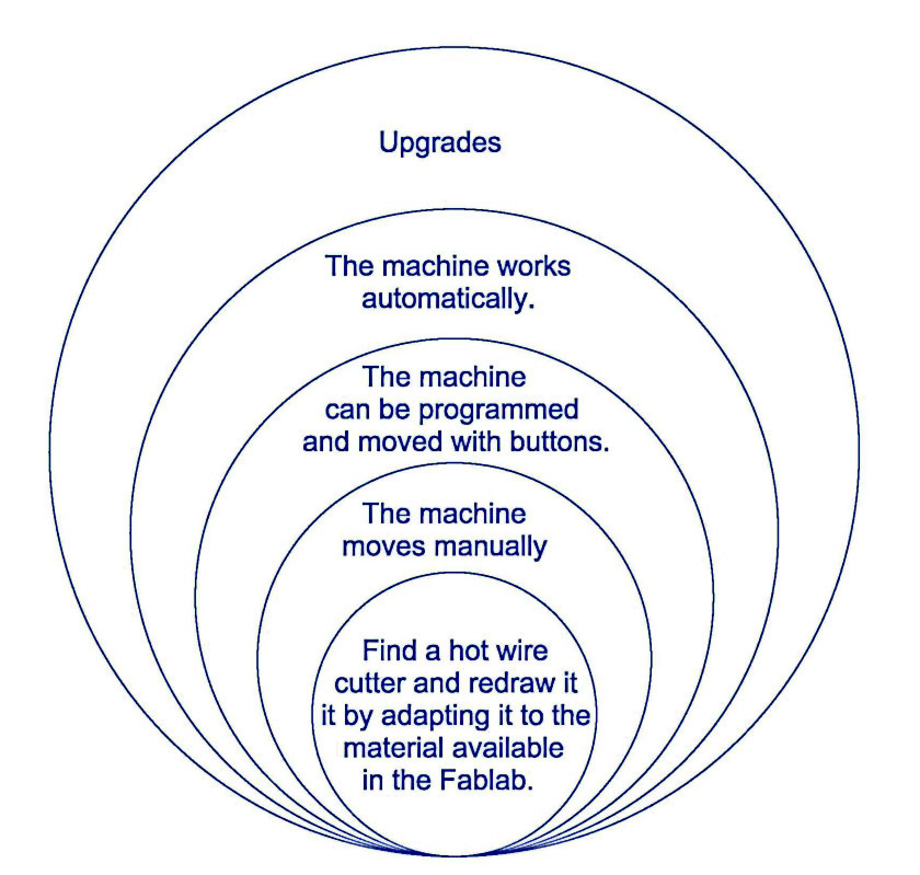
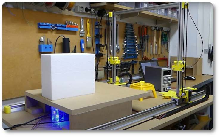
- In the first place, we have chosen a model that could inspire us to be able to design and manufacture
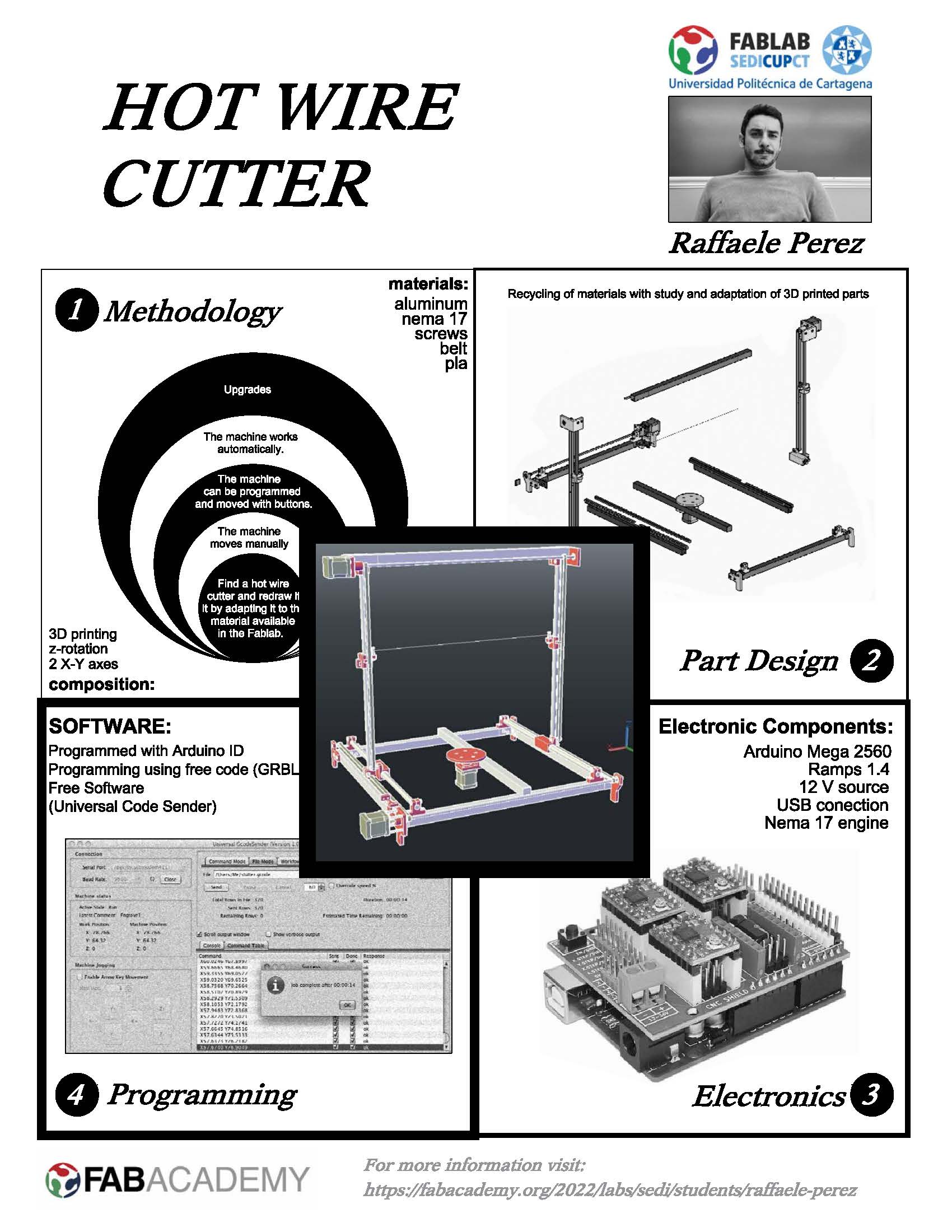
- We have established a scheme of 5 spirals, to mark the objectives of the machine
With the objectives, we have begun to make some first sketches and ideas, to identify the shape of our machine and the possible materials to be used.
inspiration machines
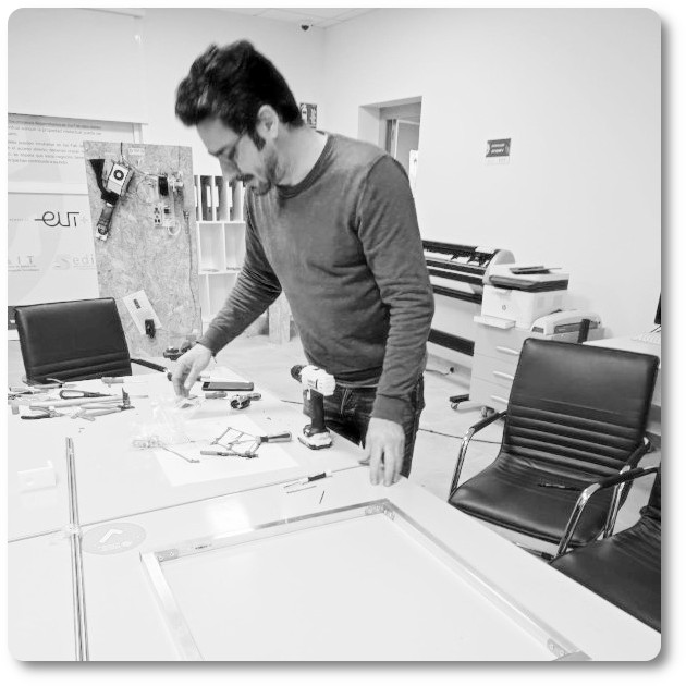
Not being able to distribute the tasks with my colleagues I have had to do the work in this order:
- Selection of the model of inspiration
- Selection and purchase of material for the machine
- Design of the pieces in 3D cad
- Study of the hardware of the reference machine and, depending on the availability of the material, the choice of the one that best suits the device.
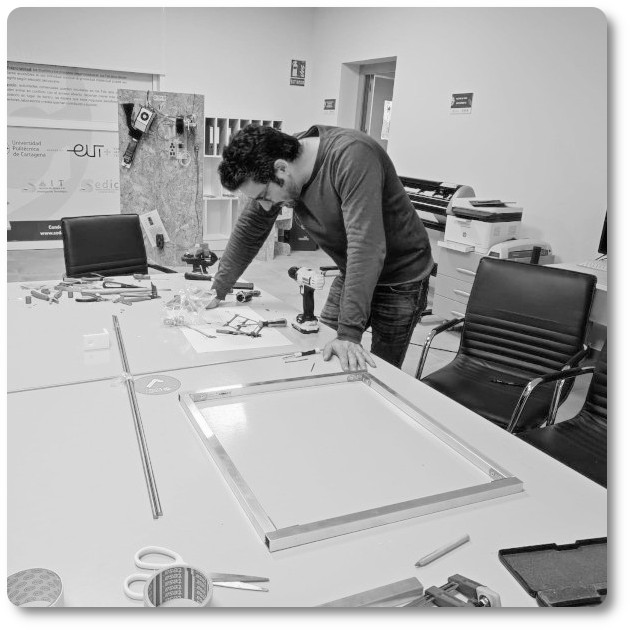
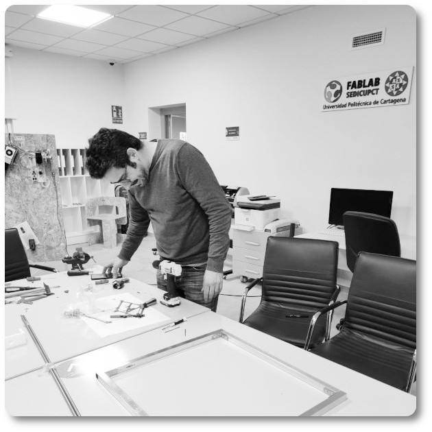
- Assembly of the machine
- Hardware assembly and check
- Study of software operation: Arduino, G-code and Working
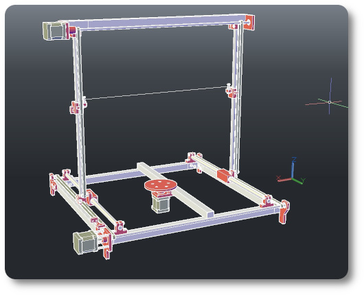
Mediante el uso de Autocad se han desarrollado las partes de la máquina. Todas las piezas han sido adaptadas a los materiales disponibles en la oficina, modificadas y no diseñadas desde cero. Aunque el modelo STL era disponible, se han vuelto a rediseñar para entender todas auqellas partes que no se aclaraban en el proyecto. La ventaja de diseñar todas las piezas es la posibilidad de conocer todas sus dimensiones y poder realizar un montaje para comprobar su funcionamiento (digitalmente).
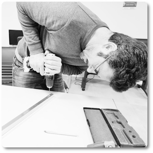
Para poder tener el mejor modelo de piezas, primero se han impreso y probado las partes mecánicas y después se han realizado las modificaciones para que el material a disposición no tuviera problemas para ser ensamblado.
Parallel to the design of the pieces, the Arduino programming and the operation of the motors have been worked on to verify that they communicate via USB and work correctly.
Finally, the Hot Wire Cutter has been assembled, tested manually and with computer controlled movement before testing the automatic working mode.
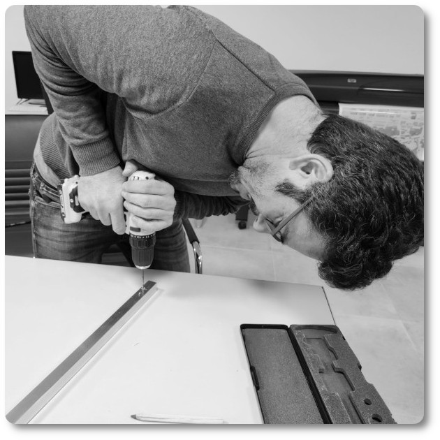
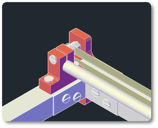
REDESIGN AND ADAPTATION OF PARTS
All joins have been redesigned. The goal was to understand the distances that are key to the proper functioning of the machine.
There were wrong measurements.
The complete structure is made of aluminium, steel and PLA with the minimum placement of screws.
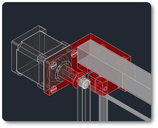
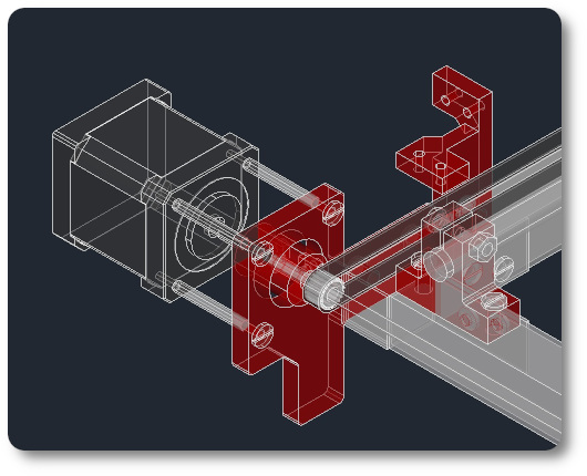
The anchors to the motors have been redesigned in order to keep the transversal distance of the belts.
The slider bars as the mechanism to slide have another size respect to the original. In the case of bars, they go from 8 mm to 6 mm in diameter. In the case of the sliders, they have a larger diameter with respect to the original.
I check that the library is green.
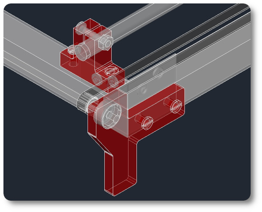
The anchor brackets have been changed for material purchased at the hardware store.
At the end the material used apart from the printed parts has been the following
- 5 uds de rectangulares de aluminio de 20*20*1*500mm
- 1 uds de rectangulares de aluminio de 20*20*1*575mm
- 4 uds de barras redondass de acero de 8*500mm
- 6 uds soportes de esquina de perfil
- Tuercas 50x M5 para perfiles con ranura en T
- Correa GT2 + Polea dentada + Polea loca
- Alambre caliente
- 4x Rodamientos lineales 10mm
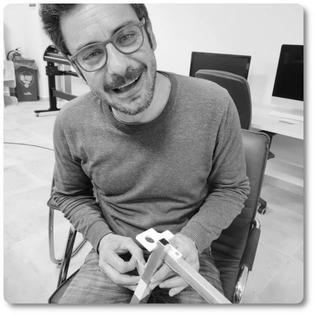
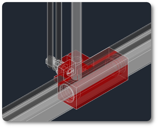
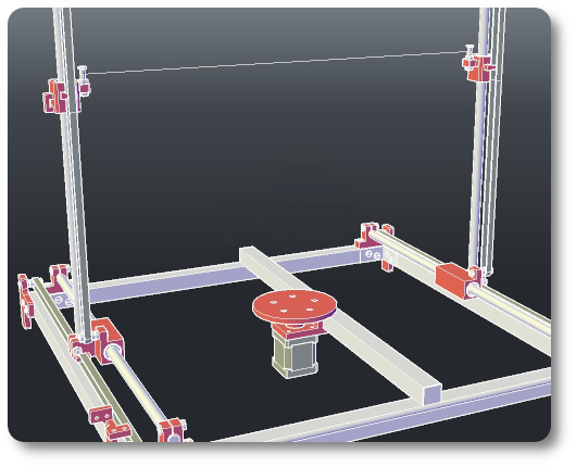
The hot wire cutter has a rotating base that will give us spectacular curved pieces. The rotating base is printed in thermoplastic, using 3D printing. A motor is attached to it so that it rotates while the thread goes down.
Render of the hot wire cutter. To take a first look at the finish of the machine.
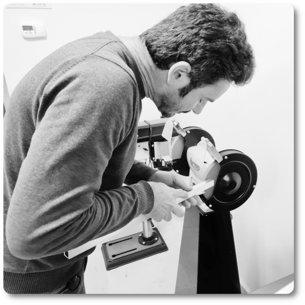
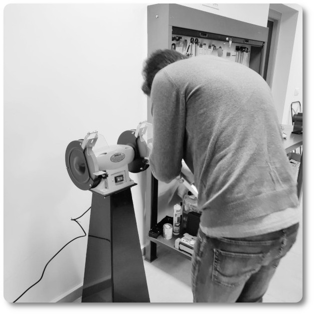
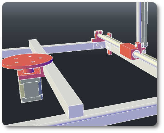
The mechanics of the cutter
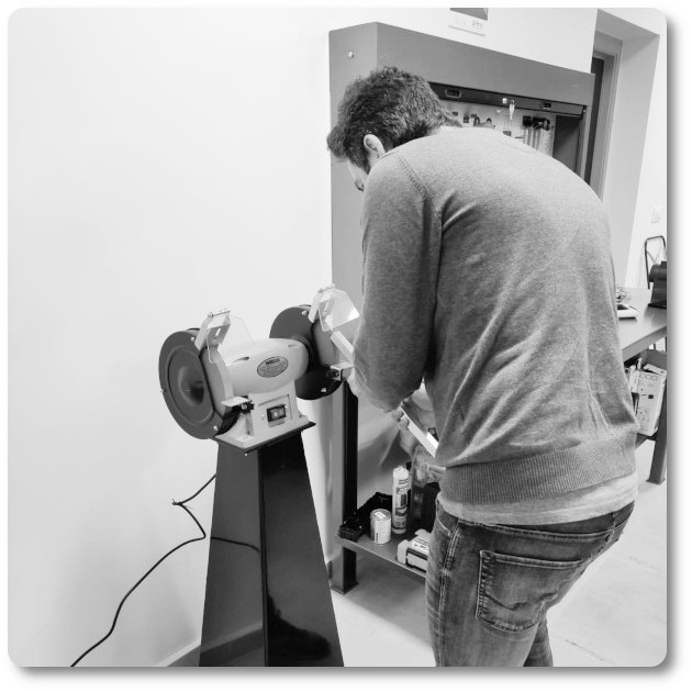
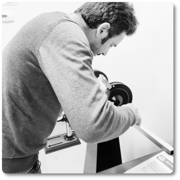
To make everything work as it should, after having assembled the whole machine I am going to check its movement. It is noted that in the x the shooting does not flow as it should. To solve the problem, I insert another bearing into the support. When I try the machine again everything flows as it should, I'm going to make a video so you can see it.
I see that everything works as it should, the bearing on the x axis, the bearing on the y axis and the egir on the z axis work very well. I'll try my luck with the electronic part.
electronic components
In order to carry out the electronic part, I have selected the following elements.
- 1 Arduino Mega 2560 board.
- 1 Ramps 1.6 / 1.5 board.
- 3 stepper motors nema 17.
- 3 A4988 drivers.
- 1 12 Vdc power supply.
- Correa GT2 + Polea dentada + Polea loca
- Alambre caliente
- 1 USB cable (A to B).
Arduino Mega 2560 is a board based on the ATmega2560 microcontroller. It has 54 digital input/outputs (of which 15 can be used as PWM outputs), 16 analog inputs, 4 UARTs, a 16Mhz crystal, USB connection, DC power jack, ICSP header, and a reset button. It is ideal for moving any CNC, so I will use it.
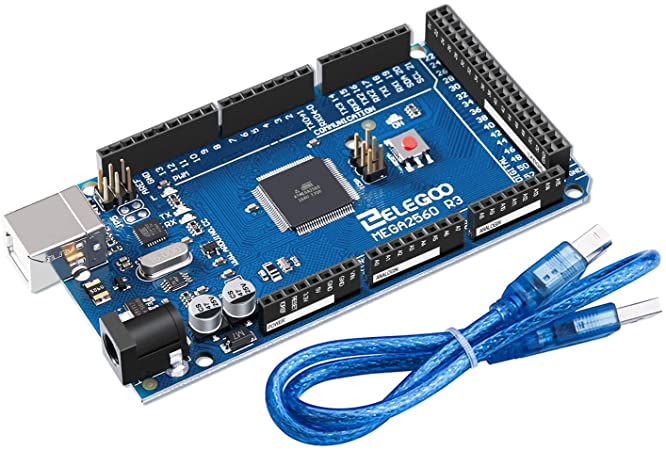
If you want to know more about this fabulous plate you just have to click Here.
Also, if you want to go deeper into the scheme and its assembly, you can click Here and the scheme will open.
The RAMPS "Raprap Arduino Mega Pololu Shield" are shields for Arduino MEGA designed to control stepper motors, usually NEMA, using POLOLU A4988 or DVR8825 drivers. They are widely used to control 3d printers, since in addition to stepper motors, we can manage all the peripherals that printers usually make up: fans, limit switches, power outlets, LCD screen. In our case we will only use it to control stepper and z motors in rotation.
In the end, the RAMPS 1.5 model was used.
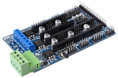
For the assembly I have followed the Ramps 1.4 connection manual, if you want to take a look at it you can access it by clicking Here.
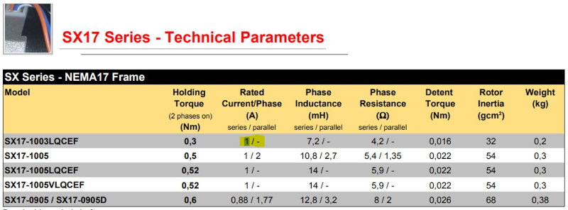
I have used three NEMA 17 motors. The Nema 17 according to characteristics have 200 steps per shift. This means that with each step we obtain a movement of 1.8º per step.
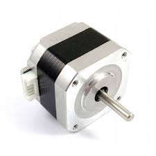
Here is a link to consult the technical sheet.
The DRV8825 is a stepper motor driver board that has a DRV8825 chip that allows control via arduino-like programming software and firmware. The DRV8825 board can supply a maximum output current of 2.5A or 1.75A RMS (with a suitable 24V 25°C heat sink).
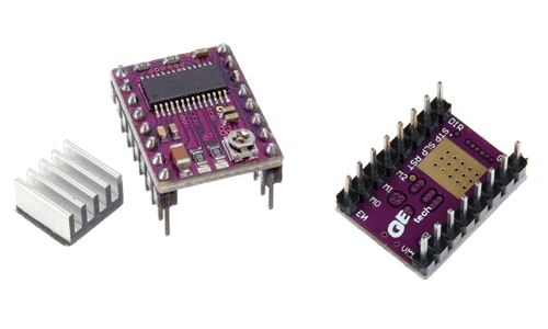
I leave two links, the datasheet and the description.
The VDC POWER SUPPLY has the mission of converting the alternating voltage into a direct voltage. In our CNC, the power supply is in charge of transforming the current from the electrical network (220V50Hz) to direct current. It is a switching power supply. It has terminals for making the AC (L, N and GND) and DC connections (3 -V terminals and 3 + V terminals).
.jpg)
Driver Adjustment
After having connected the motors, we see that they did not roll. The problem is that you have to adjust the voltage values so that they can rotate. I leave a brief description for the adjustment of the drivers.
The equation to find the driver voltage value is as follows.
Example:
If a 0.25-Ω sense resistor is used and the VREF x pin is 2.5 V, the full-scale (100%) chopping current will be 2.5 V/(5x0.5Ω) = 2A
As we are going to use complete steps we will use 70%.
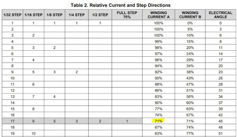
let's adjust the DRIVER.
And now to test the engine
How to build an Arduino CNC foam cutter circuit
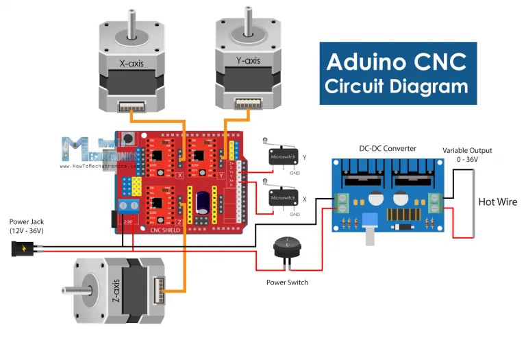
In this chapter we will build our laser cutter step by step, we will connect the electronic components. To make everything clearer I am going to leave an image so that you can see the connections between the devices.
When placing controllers make sure their orientation is correct, the potentiometer can be an indicator of what should be oriented towards the bottom side of the shield.
- First we look for the 12v power supply.
- I then connected all three stepper motors to the Arduino CNC shield, as well as the two limit switches to the X+ and Y+ end stop pins.
- At the DC converter input I added a switch so I can turn the live wire on and off separately.
- At the output of the DC converter, I simply connected the two wires from the two ends of the resistor wire.
- Finally, we can connect and power the Arduino through the USB port and power the Arduino CNC board and stepper motors through the DC power plug.
What software to use?
After having achieved its mechanical operation, having tested the motors together with the drivers and having assembled the devices as explained in the previous paragraph, it is time to generate the file that will serve as a test to verify its operation.
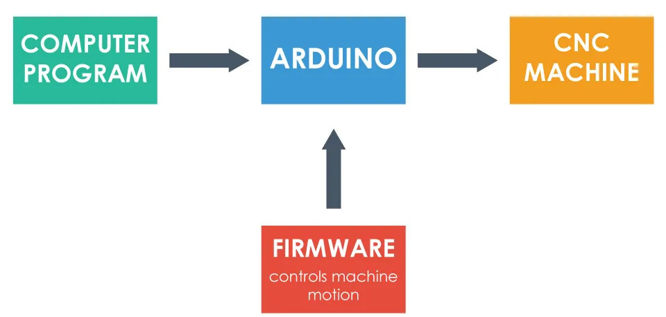
The first thing to do is look for a firmware for Arduino in order to control the machine. For this purpose, we can use the GRBL firmware. If you want to download it, just clicking Here.
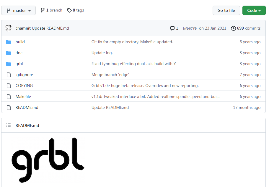
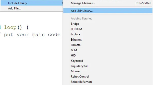
It is open source and we can download it from GitHub.com. Giving the download by clicking on "CODE" a .zip file will open. We have to extract it and paste it into the Arduino directory.
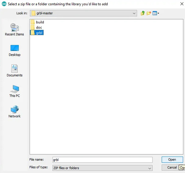
We look for the "grbl-master" folder, select it and click on the open file. We now have the GRBL in the Arduio library examples. That's cool that you don't see!!!
Next, we look at File > Examples > grbl > grblUpload. A new sketch will open which we will upload to the Arduino board. As always, we just have to select the Arduino board, the COM port and press the load button and that's it.
I forgot something. We have to configure the library to our machine, as this code is free, it is prepared for many machines, drivers and engines. We have to adjust it to our case. It is possible to do it with the arduino serial monitor, we open it and a message "Grbl 1.1h ['$' for help]" will appear. If the message does not appear, we must adjust the transmission speed to 115200.
If we type “$$” we will get a list of current commands or configurations, and it appears something like this:
- $100=250.000 (x, step/mm)
- $101=250.000 (y, step/mm)
- $102=3200.000 (z, step/mm)
- $110=500.000 (x max rate, mm/min)
- $111=500.000 (y max rate, mm/min)
- $112=500.000 (z max rate, mm/min)
- $120=10.000 (x accel, mm/sec^2)
- $121=10.000 (y accel, mm/sec^2)
- $122=10.000 (z accel, mm/sec^2)
All of these commands can or should be adjusted according to our CNC machine. For example with the first command, $100=250,000 (x, step/mm), we can adjust the steps per mm of the machine, or we can specify how many steps the motor must take so that our X axis moves 1 mm.
However, I would suggest to leave these settings as they are. There is an easier way to adjust them according to our machine using the controller software, which we will explain in the next section.
Universal G-code Sender
So once we have installed the GRBL firmware the Arduino knows how to read the G-codes and how to control the CNC machine accordingly. However, to send the G-code to the Arduino we need some kind of interface or driver software that tells the Arduino what to do, we will use the Univarsal G-code Sender.
The first thing to do is look for a firmware for Arduino in order to control the machine. For this purpose, we can use the GRBL firmware. If you want to download it, just clicking Here.
Once we download it, we need to extract the zip file, go to the "bin" folder and open any of the "ugsplatfrom" executable files. This is actually a JAVA program, so in order to run this program, we must first install the JAVA Runtime Environment.
The first step is to configure the machine or configure the GRBL parameters shown above. For that purpose, we will use the UGS Configuration Wizard.
The second step is to set a baud rate, which should be 115200, and the port our Arduino is connected to. Once we connect the Universal G-code sender with the Arduino, in the next step we can check the direction of movement of the motors.
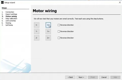
If needed, we can reverse the direction through the wizard, or by manually flipping the connection of the motor on the Arduino CNC Shield.
Now, although the speed and movement parameters have been adjusted with the Arduino monitor, we can do it again. Here it is much easier to understand how to adjust it because the configuration wizard will calculate and tell us what value we should update the parameter to.
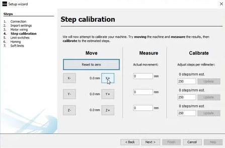
The default value is 250 steps/mm. This means that if we click on the move “x+” button, the motor will take 250 steps. Now, depending on the number of physical steps the motor has, the selected step resolution, and the type of transmission, the machine will move a certain distance.
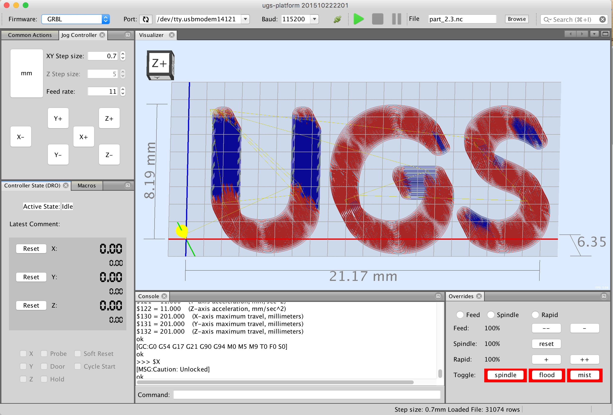
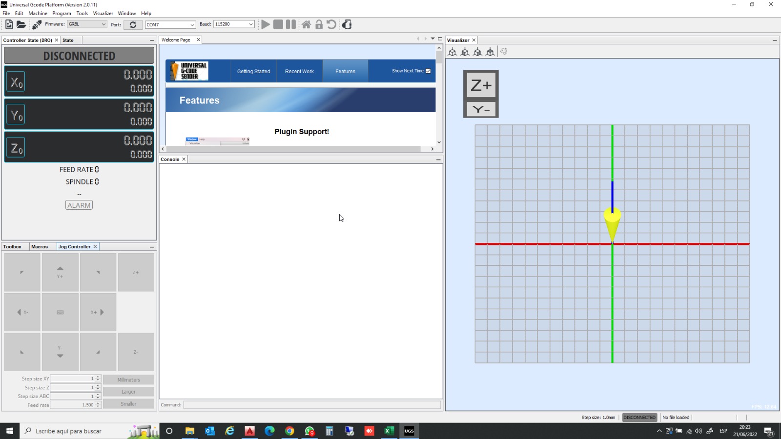
Once I have entered all the parameters, the program interface will have the following appearance
Now I am going to load the file that I have made to cut with the hot wire cutter.

Now I am going to load the file that I have made to cut with the hot wire cutter.
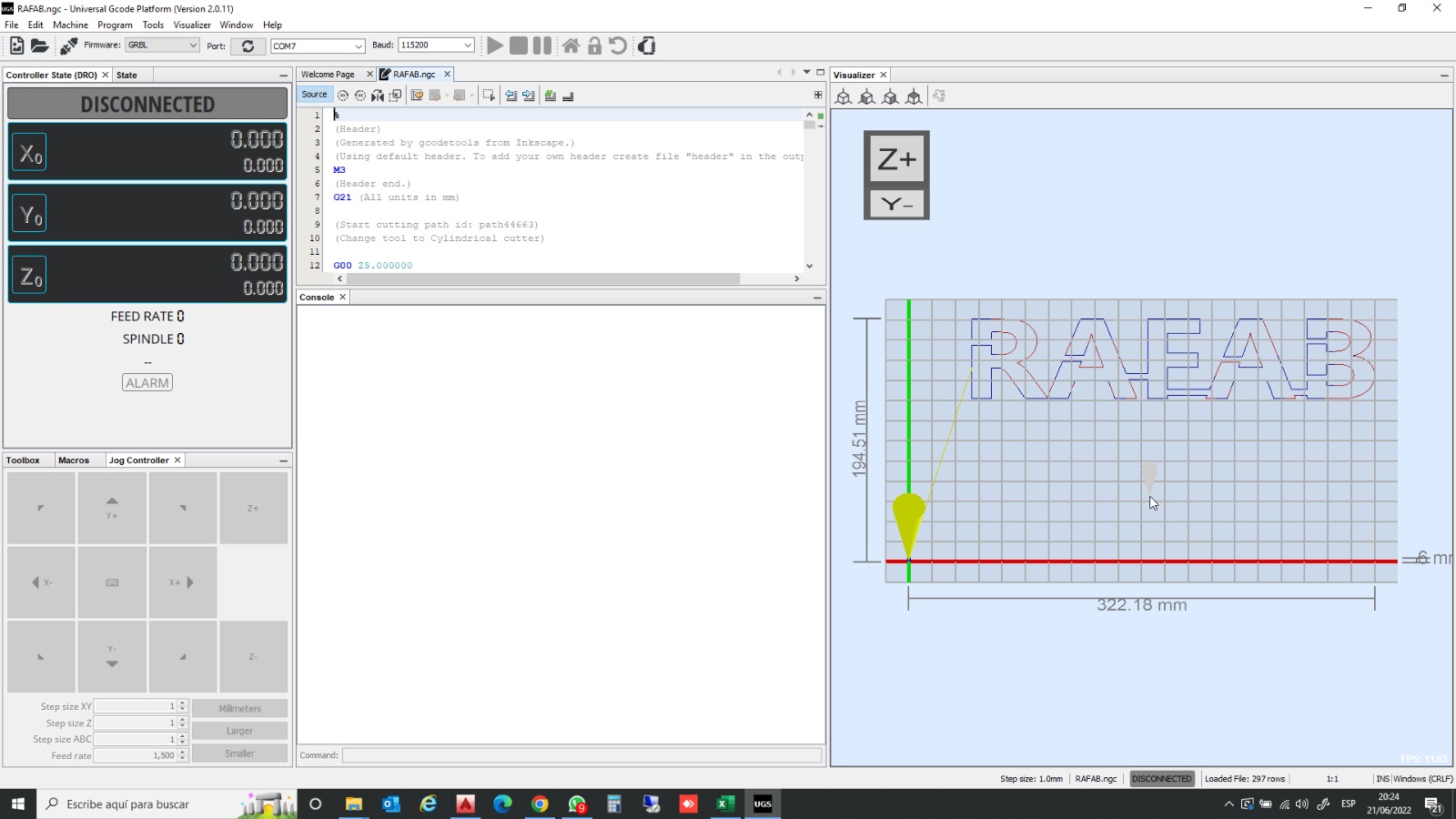
Once loaded into the program, it will look like the following. I just have to hit play and you know, I've left the video above!!!!!!
CONCLUSIONS OF THE WEEK
It has been two very hard weeks, I have run out of Easter holidays but I have enjoyed it a lot. Seeing that a machine starts from scratch and works is a blow to self-esteem!!!!!
Everything we have asked for the manufacture of the machine has not. arrived, so I had to go to the San Leroy Merlin to solve the problem. In the end I have built a laser cutter with construction parts!!!! hahaha!!
“What went wrong”: The order, nothing arrived. Many hours to adapt the pieces to the purchased ones.
It is a week where you measure yourself with time and your ability to solve problems.
“What went well”: Everything, I don't even know how I managed it.
“What will you do differently next time?”: Review the available material with much more time.
MY FILES
Here I am uploading the files that I have been making this week


