FINAL PROJECT
On this page I will write the previous questions that have helped me prepare the final project and all the documentation about the final project.
THE FIRST IDEAS ABOUT MY FINAL PROJECT
In the final scheme, visual impact has been prioritized over documentation of little interest or that is within reach of everything. I also made an outline as the cover image of my first week.
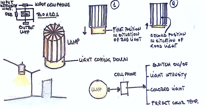
My intention is to build a lamp that is capable of adapting and communicating with the outside. I really liked the lamp made by Elena Cardiel. In my case, I would like it to be able to interact with the user to provide light without the need to get up to turn it on. Also that it is programmable depending on the type of light that I need.
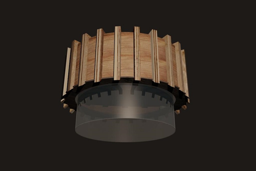
In my second week I made some renders and animation, showing the exterior design of the lamp.
Below is the rendered image of the object.
In this section we have proceeded to animate the lamp object. The idea is that all the elements are deposited from top to bottom for assembly and at the end some reinforcing structures close the lamp.
At the end of the video you can see the glass go up and down. This is a move I would like the lamp to make.
GENERALITIES
This week I am going to try to adopt some technique to take advantage of it in my final work. In the end I will do my final work on the manufacture of a lamp. In the previous weeks I had proposed a design for my lamp according to the types of input and output that I would have liked to put on it.
But I didn't like design very much, so I had been looking for some inspiration for a month, something that would have fascinated me and pushed me to work harder. An interesting project.
I needed some advice and I spoke with my friend Pedro Garcia, professor of architecture at the University of Cartagena. He told me that he really liked a lamp, a lamp designed by the Catalan architect Coderch. My reaction was immediate, I needed to look for it and know what could be cool in the design of the lamp.
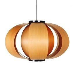
I really liked the design, it was simple and effective. From what I have been able to find out on the internet it seems that the source of inspiration is a pumpkin.
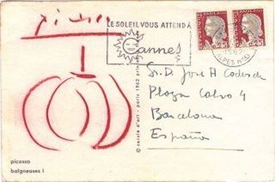
Among the stories that are told, there is one that deserves to be told. It seems that the architect, after having finished the manufacture of the lamp, sent a copy to mount to his friends and architects and artists of the time.
He also sent a copy to Picasso. The artist sent him a postcard with the design of the lamp as recognition.
Well, I'm going to post the weekly schedule and I'm going to work on the weekly homework. I have thought of making a petal of the lamp with the thermoformer. We hope everything goes well for me!!!!
Building the smart lamp
The objective of my final project, Diva codeSearch, is to find new functionalities for a famous lamp created by the architect COderch. Respecting its design, it has been redesigned again so that it incorporates functionalities that make it current and intelligent because it adapts to the environment and the people who live with it.
The operation of the first version is simple; It has a bluetooth input so that intensity can be configured from the smartphone and the segments that make it up can adopt a posture to reveal its luminous interior and add luminosity to the most demanding environments.
The design of its components makes it unique since they have been designed to be attached to it without the need to use glue. a rail is embedded within a curved rail creating fastening.
Many details have been taken care of, such as the exterior segments that are made of flexible wood.
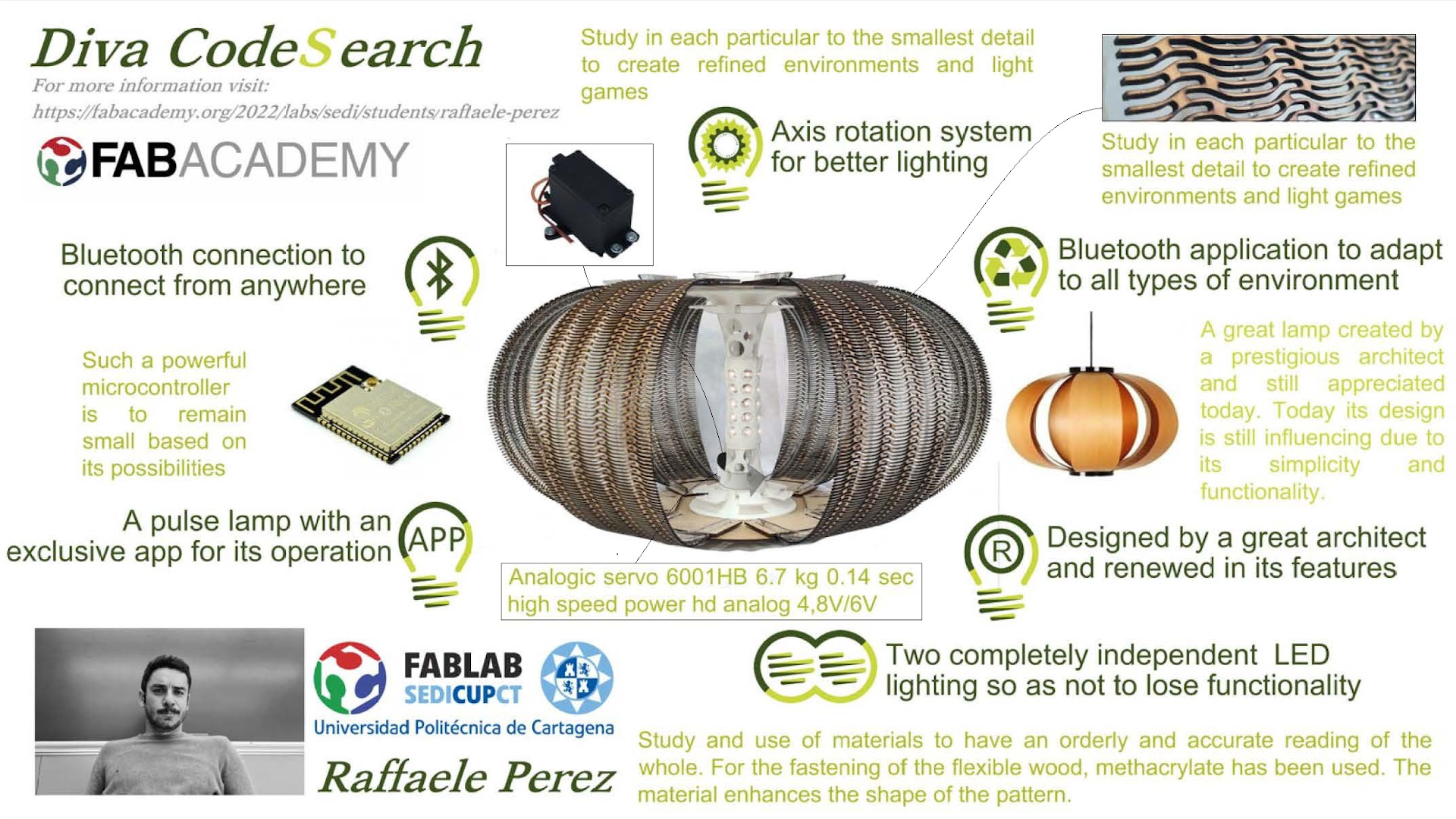
By pressing a button or using the slider on the phone to, the stepper motors are activated to go to the desired level, turning the dial of each having a different setting.
Apart from the presentation, a video has also been made to understand how it works. In it you can see a series of things although many are hidden.
For example, not all the techniques that have been carried out throughout the academy and that have been used in the manufacture of the lamp are appreciated.
For these reasons, I will name them here:
- WEEK 02: COMPUTER-AIDED DESIGN
- WEEK 03: COMPUTER-CONTROLLED CUTTING
- WEEK 04: ELECTRONICS PRODUCTION
- WEEK 05: 3D SCANNING AND PRINTING
- WEEK 06: ELECTRONICS DESIGN
- WEEK 08: EMBEDDED PROGRAMMING
- WEEK 09: MOLDING AND CASTING
- WEEK 10: OUTPUT DEVICES
- WEEK 11: MECHANICAL DESIGN, MACHINE DESIGN
- WEEK 12: INPUT DEVICES
- WEEK 13: NETWORKING AND COMMUNICATIONS
- WEEK 14: INTERFACE AND APPLICATION PROGRAMMING
Here, we have de video
HOW MUCH WILL THEY COST? / WHERE WILL COME FROM?
These two responses are defined in the following table
| PART | MATERIAL AND COMMENTS | PRICE | FONT |
|---|---|---|---|
| Axis of rotation and clamping of the lamp Base | PLA 850 White (22 hours and 36 minutes) 251.40 gr [Ender 3pro printer] | 5,34 € | click here. |
| Axis of rotation and fastening of the lamp Top part | PLA 850 White (22 hours and 25 minutes) 245.89 gr [Ender 3pro printer] | 5,21 € | click here. |
| Top cap | PLA 850 White (7 hours and 50 minutes) 82.32 gr [Ender 3pro printer] | 1,75 € | click here. |
| Bottom plug | PLA 850 White (7 hours and 45 minutes) 78.30 gr [Ender 3pro printer] | 1,66 € | click here. |
| 14 pcs Inner Segment Closure units | PLA 850 White (2 day 2 hours and 28 minutes) 14x45,87 gr [Ender 3pro printer] | 11,75 € | click here. |
| Threaded rod | 1x (8mm x330mm) | 15,99 € | click here. |
| Nema17 motors | NEMA17 1.3A 40mm | 17,84 € | click here. |
| flexible fixation | (6 x 8 x 25) mm, Diameter: 19 mm | 8,99 € | click here. |
| ESP32-WROOM-32D | MODULO WIFI 32MBITS SPI FLASH | 2,42 € | click here. |
| Power supply | 240W 12V 21A | 21,15 € | click here. |
| LED transformer 12V 24V 6W 9W | 12V 9 W | 10,69 € | click here. |
| 5V regulator | 5v; 1 A | 0,83 € | click here. |
| 3V regulator | 3,3v; 1 A | 0,70 € | click here. |
| 8825 DRV driver modules | DRV8825 18 pins | 1,37 € | click here. |
| 100uf capacitors | Aluminum electrolytic capacitors (with radial leads) | 1,66 € | click here. |
| 3 0K resistors | BRIDGE RES SMD 0 OHM 1/4W 1206 | 1,21 € | click here. |
| 2 1uF capacitors | CER PLUG 1UF 50V X7R 1206 | 0,48 € | click here. |
| 10uf capacitor | CER PLUG 10UF 35V X5R 1206 | 0,43 € | click here. |
| 1K resistor | RES SMD 1K OHMIOS 1% 1/4W 1206 | 0,10 € | click here. |
| 1 smd led (blue) | LED AZUL TRANSPARENTE CHIP SMD | 0,46 € | click here. |
| Reset button | TOUCH SWITCH SPST-NO 0.05A 24V | 0,42 € | click here. |
| Switch | Slide Switch, SPDT, Through Hole, SSSS9, 100 mA | 1,20 € | click here. |
| 4 pcs Male Connecting Pin | 40POS 2.54MM SMD HEAD CONNECTOR | 4,87 € | click here. |
| 32-pin female connection for controller | CONN HDR 8POS 0.1 TIN PCB | 12,80 € | click here. |
| 2-pin square power connector | TERM BLK 2POS SIDE IN 3.5MM PCB | 1,07 € | click here. |
| 6 pcs MDF boards | Raw MDF board 61x122x0.3 cm (width height thickness) | 31,14 € | click here. |
| Polyurethane foam for mold | High quality Phenolic foam: | 9,60 € | click here. |
| Epoxy resin + hardener | epoxy resin + hardener | 17,99 € | click here. |
| 2 pcs natural linen fabric | 100x148 Cms linen | 17,95 € | click here. |
| TOTAL | 207,07 |
€ |
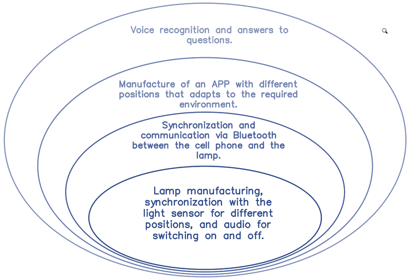
SPIRAL MODEL DIAGRAM
This scheme intends to structure the scope by stages. In the smallest spiral we will have the predetermined minimum objective and in the largest one the top of the scope of the project.
Intellectual Property Diva CodeSearch:
As I already said in week 17 about intellectual property, my intention is to use my project to make it Open Source, as I already explained, in my daily work I dedicate myself to helping the students of the architecture school to make prototypes and architectural plastics. I would love for my lamp to serve as an example and inspiration so that you can continue with my work.
I would like it to be used as a starting point to create new evolutions and experiment with electronics.
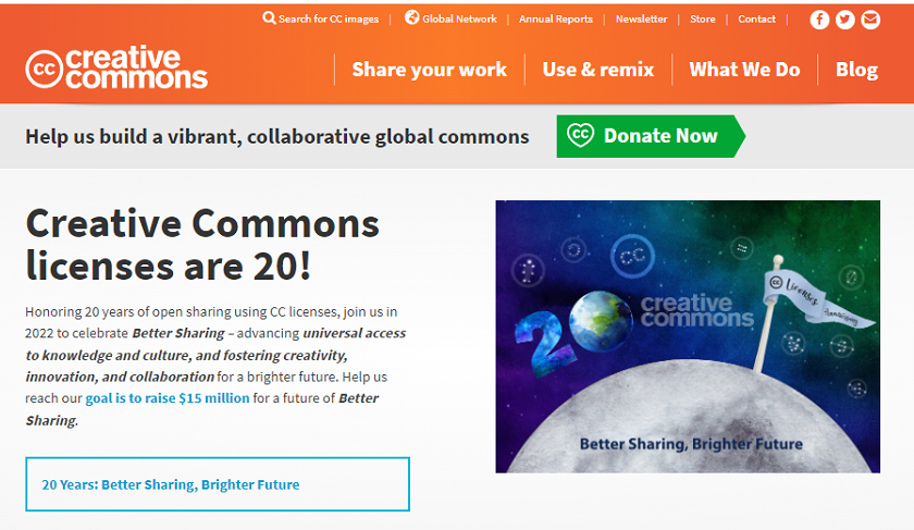
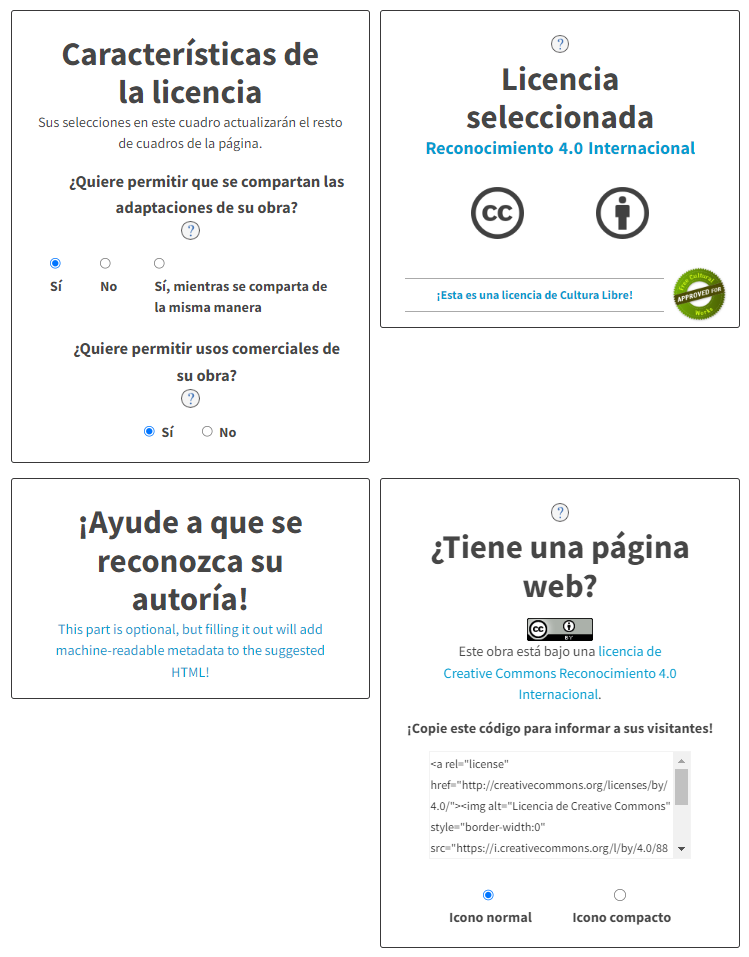
In the end I have chosen this page, it is a free license
I follow this steps recomended in the page
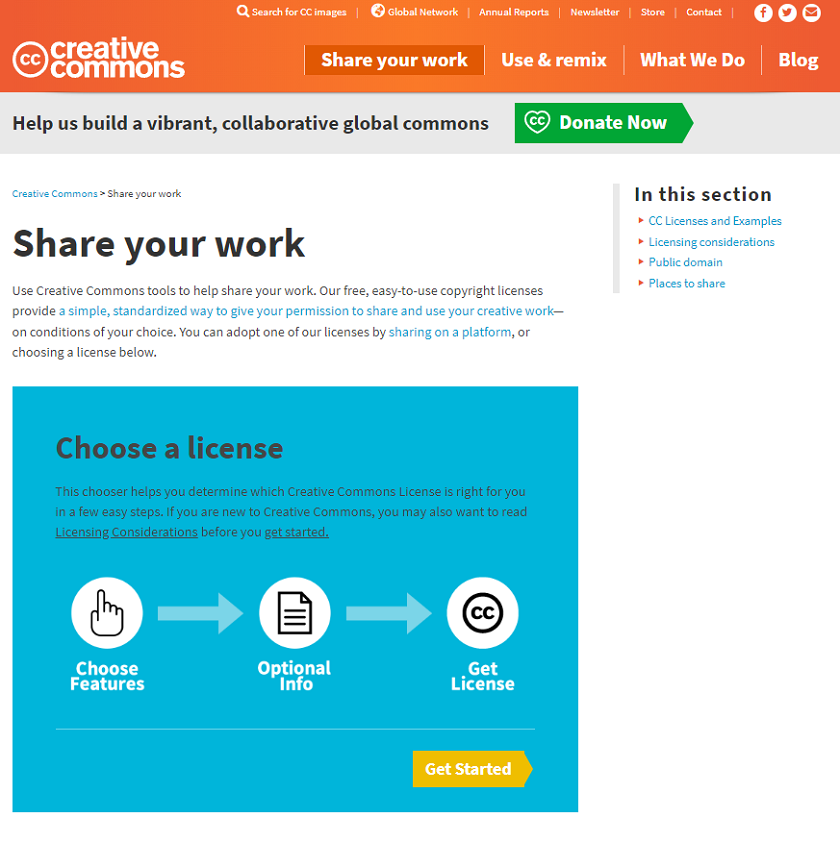
I have obtained a code that I have posted on my website
INSTRUCTIONS FOR MOUNTING THE LAMP
In this section, for those less used to dealing with digital fabrication projects, I will try to give graphic instructions and comments for the assembly of the lamp.
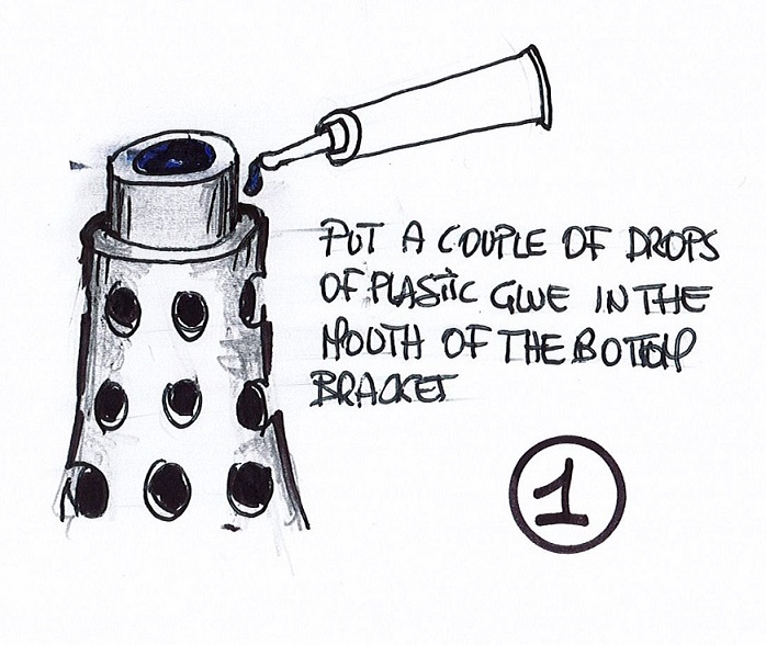
In the first image it is about joining the two supports printed in PLA with a male-female connection. It is advisable to give it a little glue for plastic or the fast one. Although there is no need, as each impression has its characteristics, it is good to ensure it.
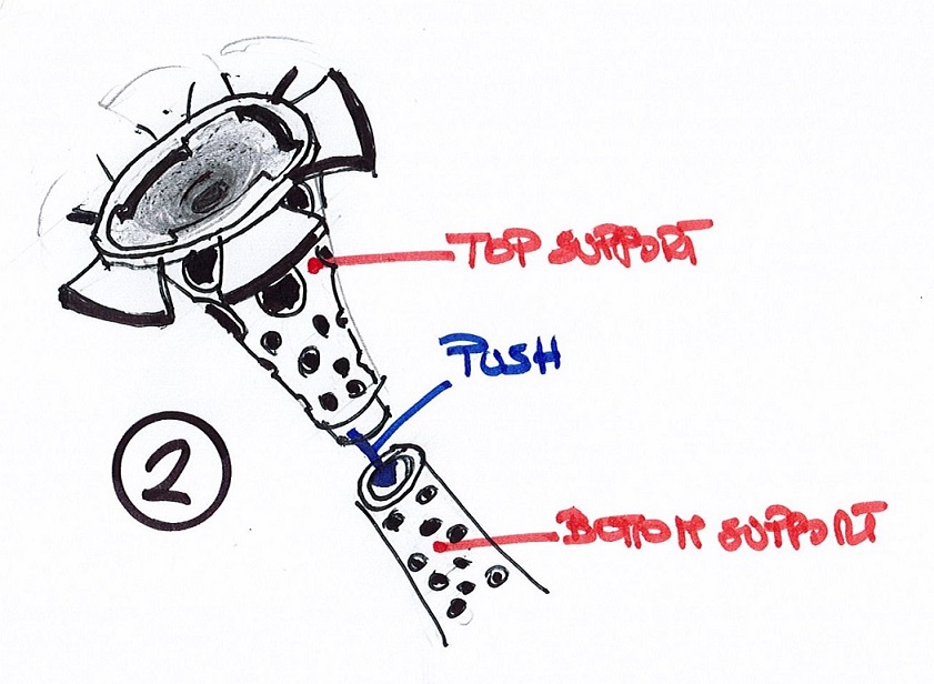
The second image makes us understand how the two supports are connected.
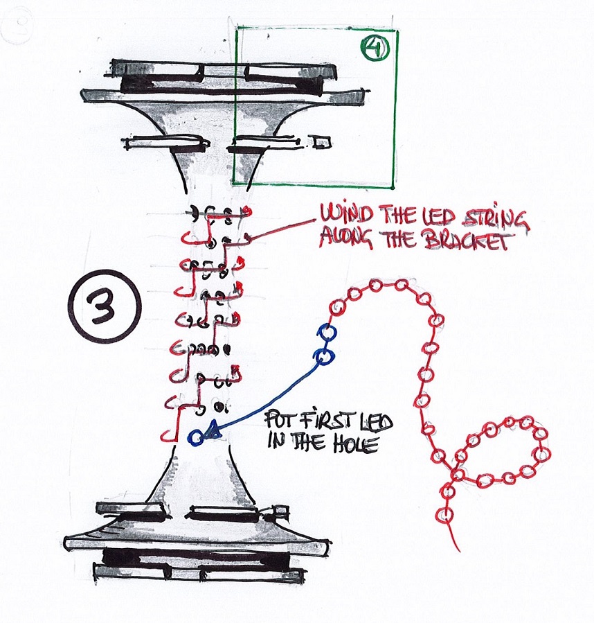
Image 3 explains that once we have created the chain of LEDs, we must adapt it to the holes left in the supports in a rotating way and going up a step.
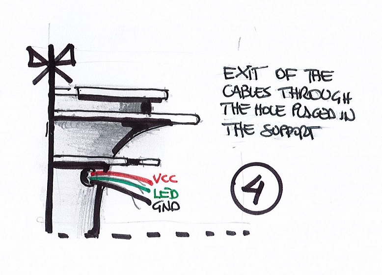
In the fourth image, it is explained that the excess cables are taken out through a hole so that they cannot move when the inner segments rotate
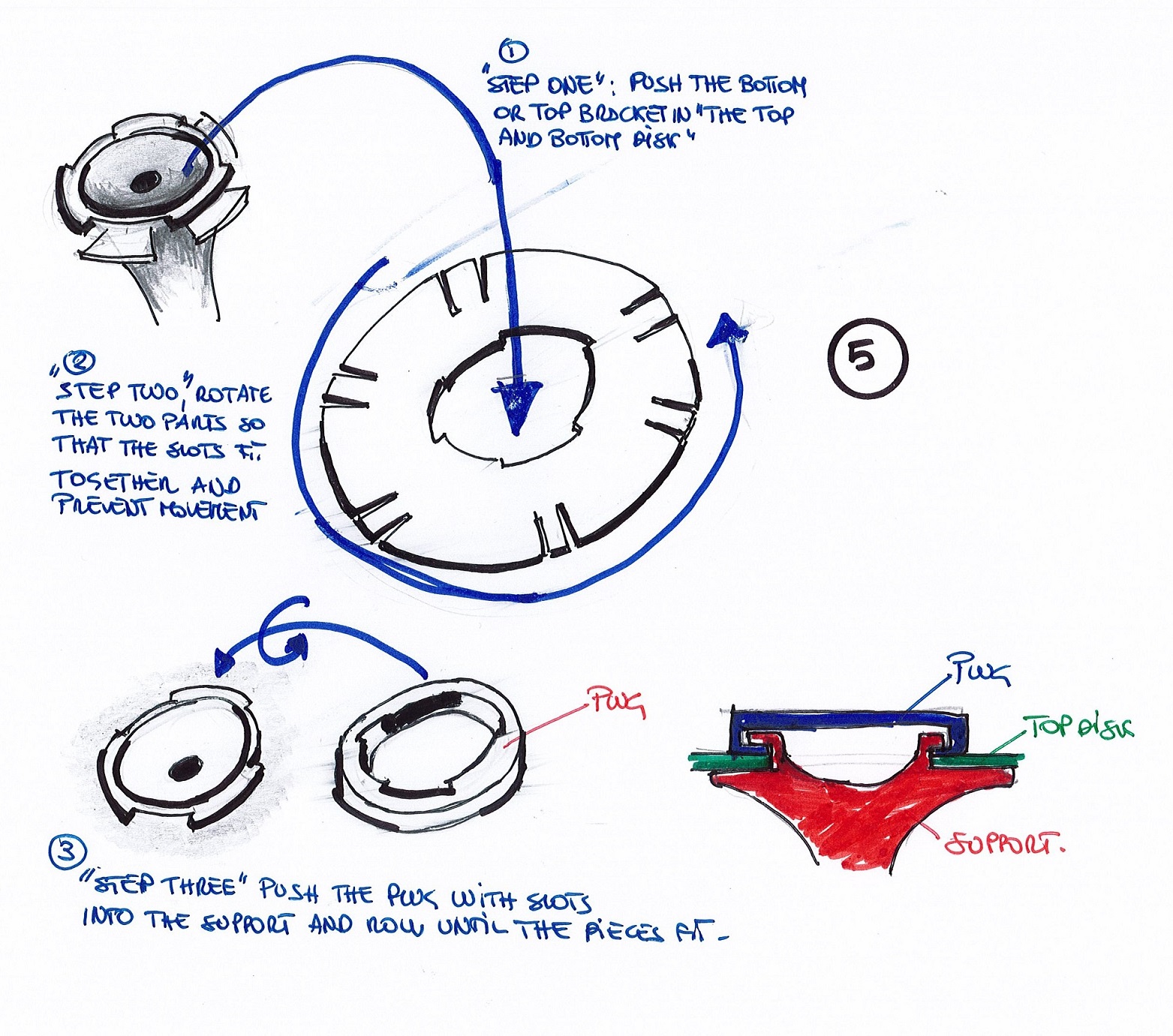
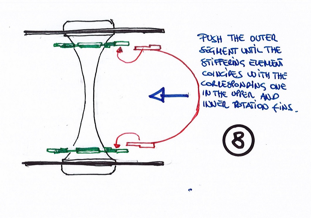
Image 5 explains that once we have made the support it is time to connect the upper and lower discs, as you can see for the connection they have been drawn so that once they are inserted a small rotation is applied and thus they do not come out again. To finish, a cap has been designed, its slots are crescent. When it is tightened, all one piece remains, the support, the disc and the end cap.
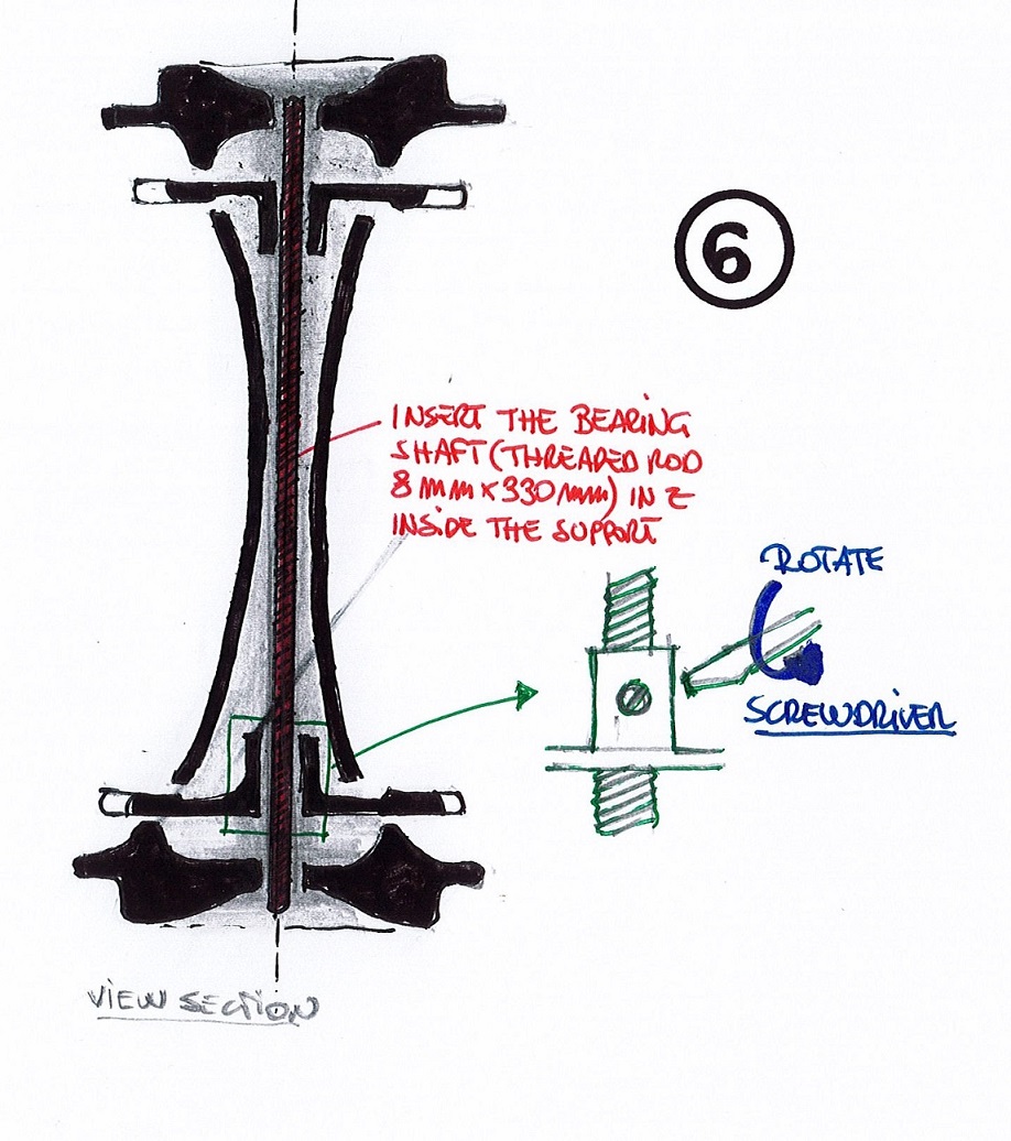
Another step is to introduce the bearing support that will connect the two upper and lower discs where the inner segments will be placed.
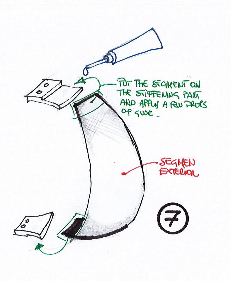
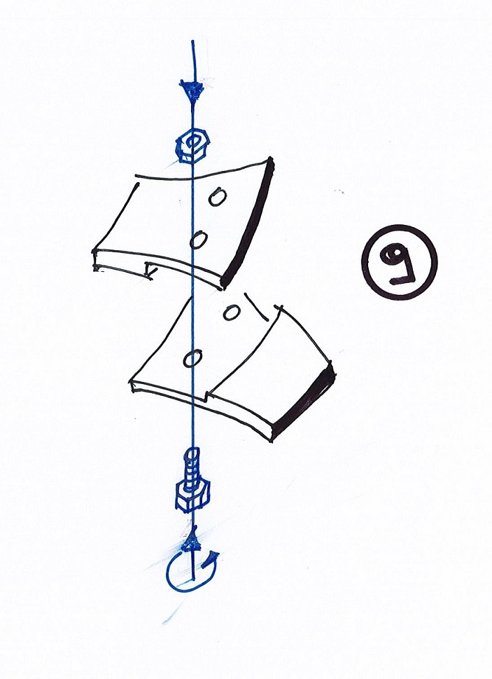
Now we finish the inner segment, to adapt it to the discs, some negative pieces have been designed that blend perfectly with the cloths.
Once the ends are positioned, we screw them
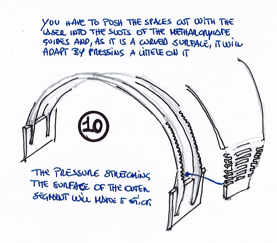
We push the shape cut with the laser inside the jagged methacrylate and the mosmo will be held by traction.
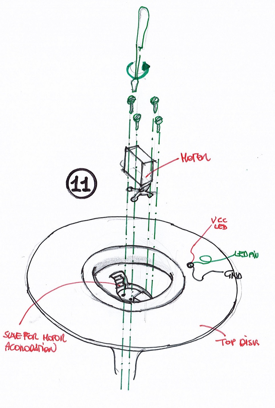
We proceed to mount the motor, in the upper part a hole has been left so that it can be coupled without problems, some holes have also been left to receive the screws of the blades.
As in the figure, all the components are assembled since the grooves have been left to receive them.
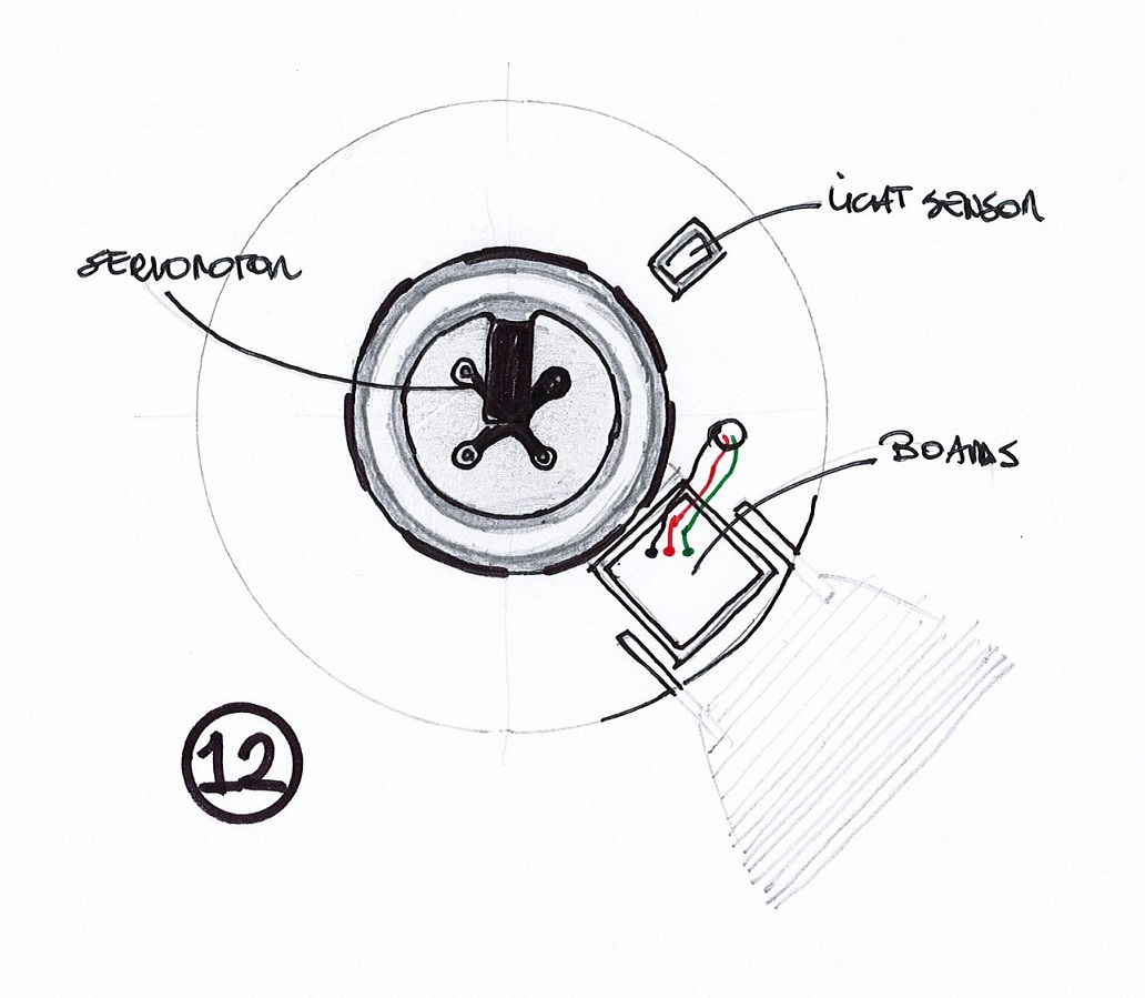
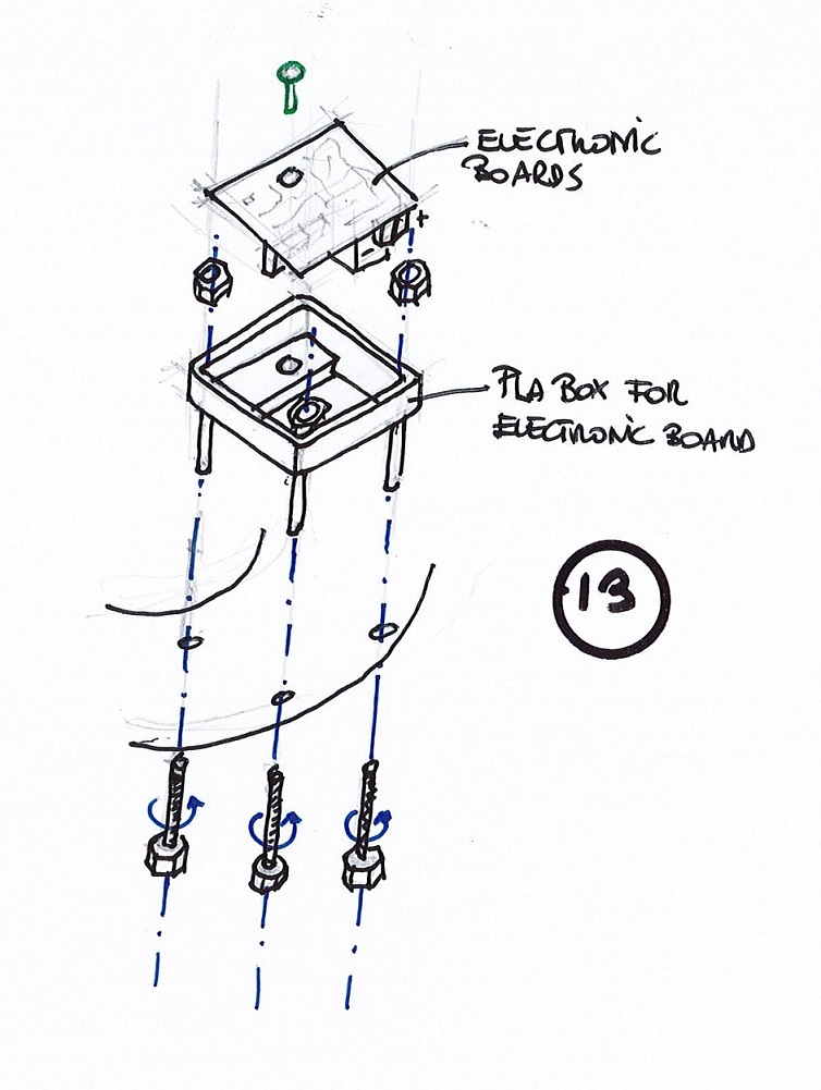
Assemble the base of the boardas on the external disk, then the boards is fixed to the prepared box. The base is empty at the bottom to mount the cables.
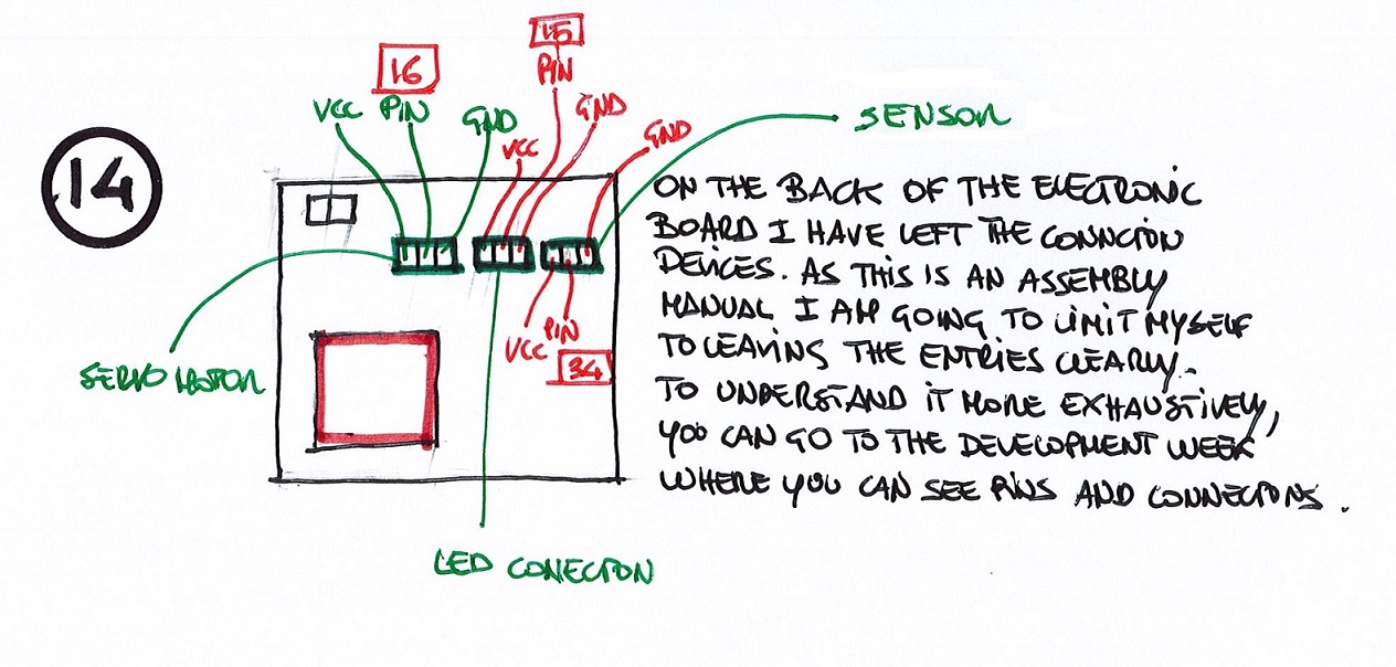
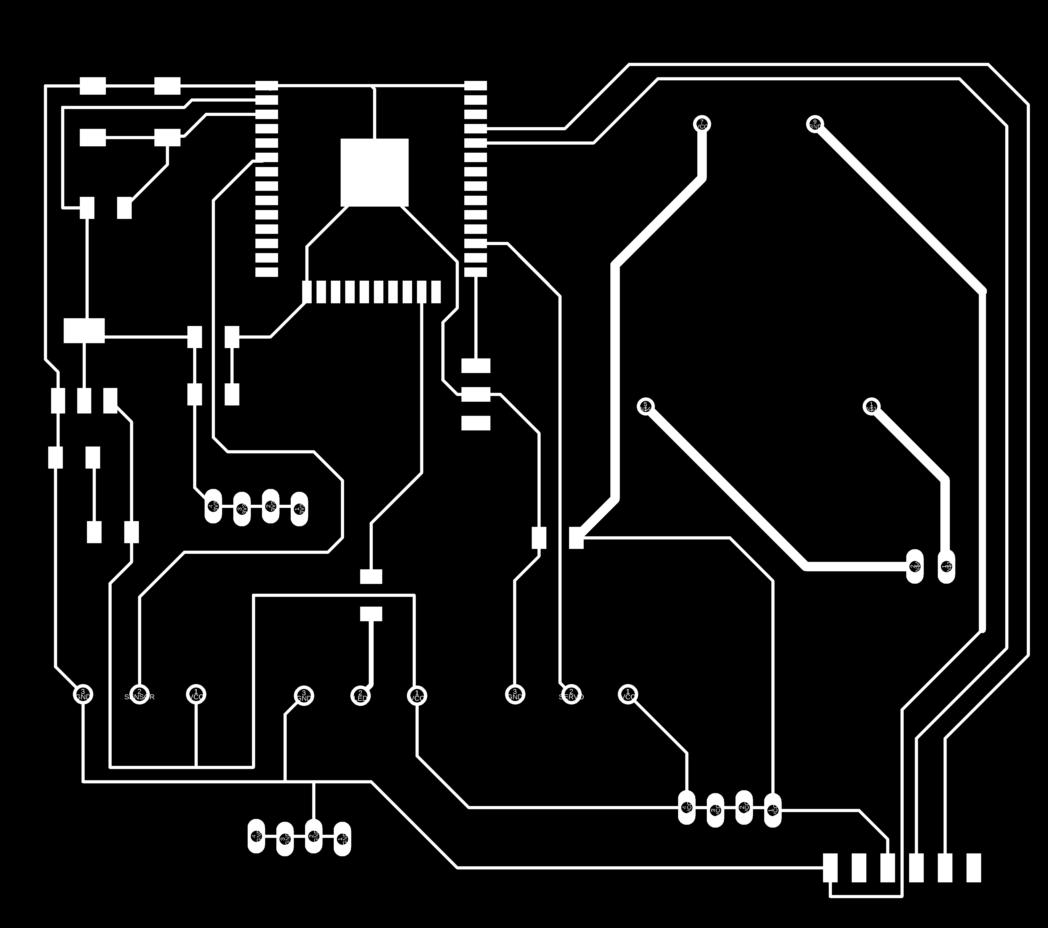
I leave a scheme of easy interpretation for the connection of the devices
With this is all, we just have to enjoy it.
CONCLUSIONS OF THE WEEK
A really hard week but full of satisfaction, seeing that things work out in the end is a huge pleasure. I am very satisfied
It is a week in which you work in the dark, you work from sun to sun and you have only one question in your head: will it work??
I love that you can work things out and think it's just the beginning.
“What went wrong”: Everything had minor adjustment issues but nothing really worked wrong. Perhaps the epoxy resin was an already used pot and the outer segment was not hard. I solved it by adding a folded plastic sheet to it.
“What went well”: That I have learned things and others are at the door to achieve it later. It is an evolving world.
“What will you do differently next time?”: Nothing, the experience is cool!!!!
MY FILES
Here I am uploading the files that I have been making this week
Main parts of this document
-
Introduction
-
Final project


