WEEK 04
ON THIS PAGE WE WILL FIND A BRIEF DESCRIPTION OF MY JOB THROUGHOUT THE FOURTH WEEK
GENERALITIES
This week, like the previous one, I will have to fight with my two tasks: individual and group. I have to confess that although I don't have much idea about electronics, I am very passionate about the subject and I really enjoy learning about it.
In individual work, the task is to make a PCB and also program it to work. The group work intends that we get to know more deeply the machine that I have used to manufacture the PCBs.
At the top right there is a link to enter group work.
I am going to try to document all the work done and therefore I will start by making a table with my weekly work divided by tasks.
| Day | Wenesday | Thursday | Friday | Saturday | Sunday | Monday | Tuesday |
|---|---|---|---|---|---|---|---|
| 09:00 | |||||||
| 10:00 | Meeting CT | Assigments | Assigments | Local Review | |||
| 11:00 | Meeting CT | Assigments | Assigments | Local Review | |||
| 12:00 | Assigments | Assigments | |||||
| 13:00 | Assigments | Assigments | Regional Review | ||||
| 14:00 | Assigments | Assigments | Regional Review | ||||
| 15:00 | Fabacademy | Practice | Assigments | Practice | |||
| 16:00 | Fabacademy | Practice | Assigments | Practice | Review Documents | ||
| 17:00 | Fabacademy | Practice | Assigments | Assigments | Practice | Review Documents | |
| 18:00 | Fabacademy | Practice | Assigments | Assigments | Practice | Review Documents | |
| 19:00 | Practice | Assigments | Assigments | Practice | Review Documents | ||
| 20:00 | |||||||
| 21:00 | Tutorial | Tutorial | Assigments | write Documents | |||
| 22:00 | Tutorial | Tutorial | Assigments | write Documents | Write Documents | ||
| 23:00 | Tutorial | Tutorial | write Documents | Write Documents | |||
| 24:00 | Tutorial | Tutorial | write Documents | ||||
| 01:00 | |||||||
| 02:00 |
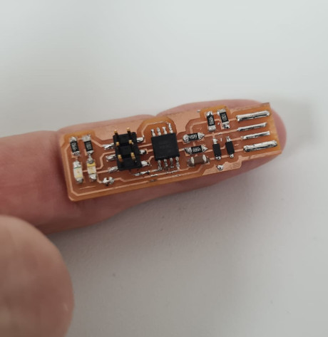
I was very afraid of making my board with SMD components, SMT technology. Not understanding much of this technology made me curious. I have to admit that although they are very small, everything is extremely cheap and they work wonderfully. If they are well made they are more resistant to having little weight (in my case they fell to the ground 2 or 3 times without breaking, well being so small I burned myself a couple of times).
PRODUCTION PROCESS
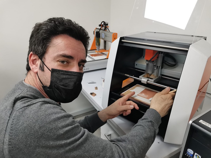
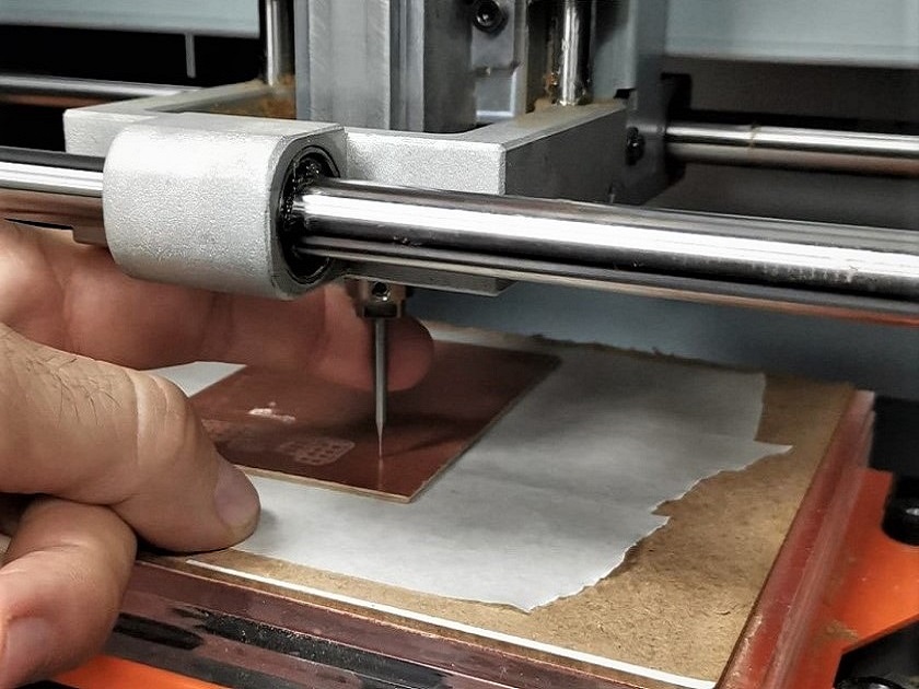
The first thing to do is to accommodate the copper board on the work surface of the machine. The stability must be well assured because the milling process can move it and the result would be a bad result.
Once we have secured the copper plate, we need to select the rods and the z-height. We will use a 1/64 cutter to draw the tracks and a 1/32 cutter for the outer cut. The machine does not have a sensor to help it calculate the height, so it will have to be done manually. To do such an operation we first select the 1/64 rod. The choice is mandatory, for quality reasons, the prints will be made first, and then the contours will be made.
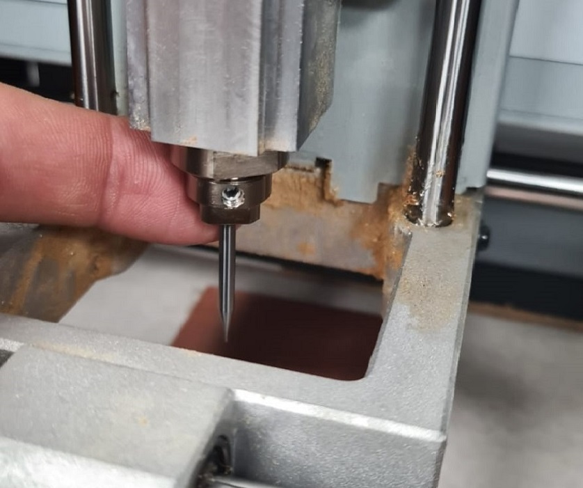 Milling tip setting
From the control software of the milling machine we lower the rod until it is very close to the board. Then we secure it with our fingers and release it. The rod will fall slowly until it touches the copper. With this we have the physical adjustment at the zero point and by pressing the z button in the milling machine software we also leave it fixed in the parameters.
After having adjusted the milling tip, we will go to the web to download the images of the plate that I want to manufacture. You can access the instructions by clicking here.
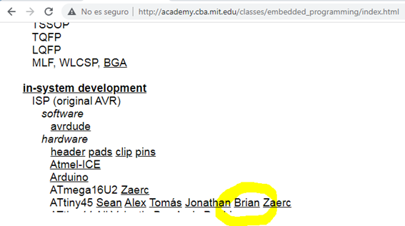 Step 1: Go to the link where the instructions are
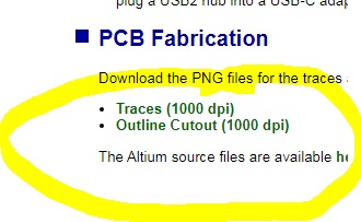 Step 2: Find the two images of the circuit
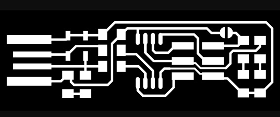 Step 3: Indoor Image
 Step 4: Outside Image
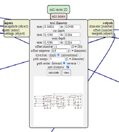
Another step is to look for the intermediate software that we need to introduce the images to be manufactured and introduce it in the machine software. In this case we will look for the software mods.
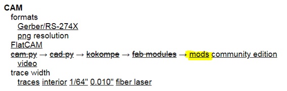
It is very simple, the environment works with several menus connected to each other, the milling, design, saving and milling menus. They are all connected to each other and you only have to enter the parameters of the printer and the model that will result in a file that we will pass to the milling machine.
 Software parameters mods
The model I have chosen for manufacturing is Brian's. To do this I download the internal and external images for manufacturing.
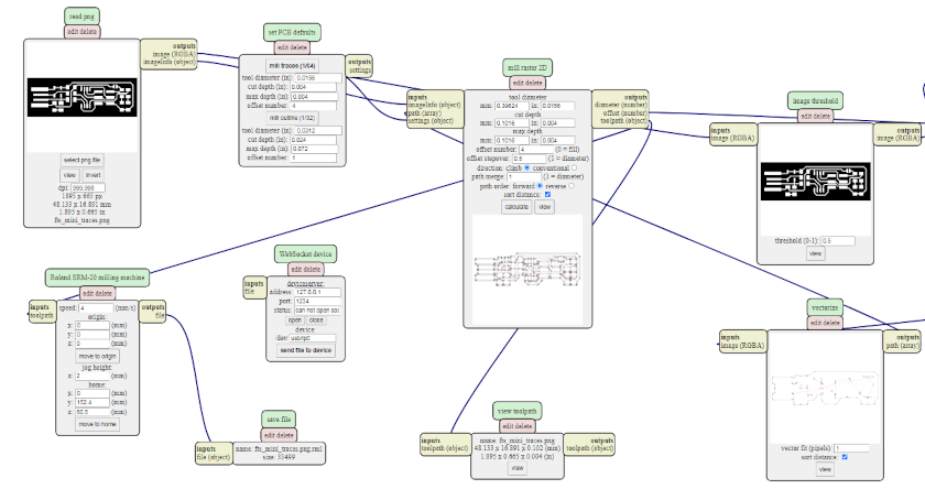
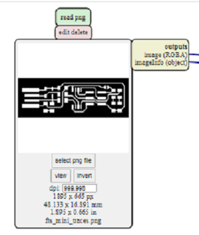 Selecting the png image
 Calculating and outputting the file
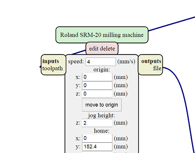 Setting the mill parameters.
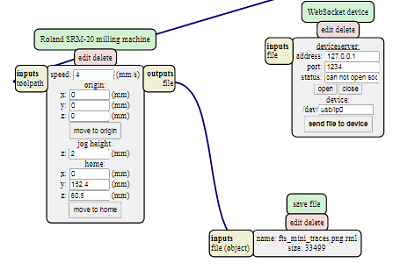 File saving parameters.
The first test I'm going to do to see if Mods really work is to grind the programmer. To perform the operation, I choose the mill 1/64, speed at 4 mm/s,. I send it to the machine and something goes wrong. My instructor Álvaro explains to me that you have to use a more recent mod file. To do this, check for the latest update and let's get started.
Fortunately everything is going well and the milling is spectacular, so we proceed to work with the outer cut. We repeat the same operation for the outer cut. I disassemble the 1/64 bit and when I put it in the box I mark it with a line to indicate that it has been used once.
 Changing the milling tip
I go to mods to insert the PNG image, I am going to adjust the parameters of the thickness of the cutter and the speed. Later I will see the image with the milling directions and the number of turns it will make. At the end I click save file and go to the milling machine software. We adjust Z again, I hit the CUT button and there I load the image and hit output.
The milling machine starts to work but we have not made a mistake with the height of z so we will repeat the operation. This time everything goes well, done. I can start the second part now. The welder.
 Adjusting the Z height
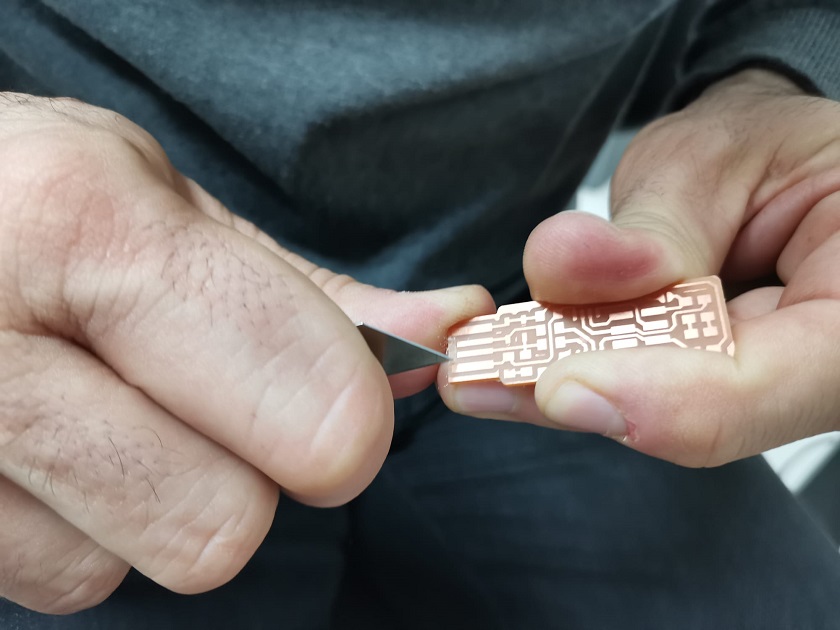 Finished boards
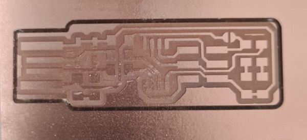 Boards before removal
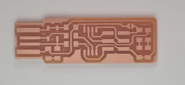 Boards almost finished
PREPARATION OF THE SMD COMPONENTS FOR THE BOARD
In order to make the plate, my instructor Gustavo Macián explains to me that the components that are extracted from the container must be secured with a tape. They are so small that many get confused and if they are not put on a tape with the name next to it, you could lose it.
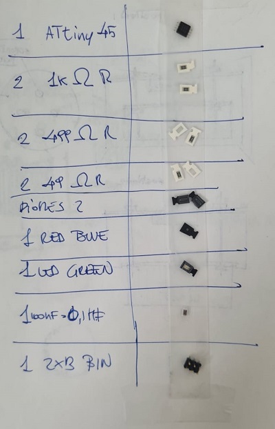
The only variant to the selected components has been to replace the red light with the blue one. I didn't like the red light that should give the power signal. Red gives an idea of errors and is not cool.
THE WELDING OF THE ELEMENTS
About welding I have learned the following:
- You do not have to be afraid.
- Tin does not stick to plastic.
- You have to give a point before inserting the component.
- Once welded it is good to carry out a test in case there are tracks that overlap.
- It is necessary to ensure if the component is welded to the track (check)
- You have to pay close attention to microprocessors, LEDs and diodes.
Now I'm going to post some photos of the welding work while I'm doing it.
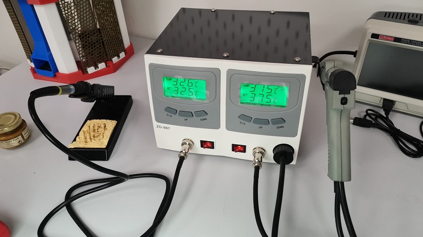 Welding machine that I have used
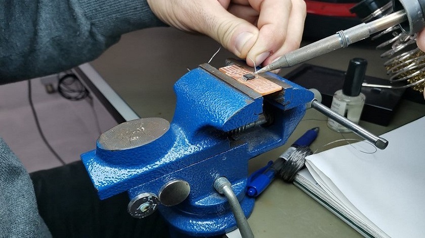 Starting to weld
 Soldering all the components
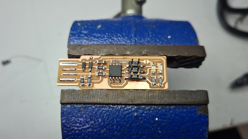 boards finished
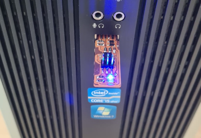 Boards tested and working
 Greetings from Cartagena, first part ends.
PREPARING THE CIRCUIT PROGRAMMER
In this section I will describe all the steps performed for the preparation of the programmer. It must be said that it has not been easy, although in the end the experiences of my instructors have helped me to overcome all the mistakes made.
After having made the electronic board, we started to program my device. For this operation, I will follow a tutorial.
Following the tutorial, the first step was to install the Atmel GNU Toolchain. It was a bit difficult to find because the tutorial file was not available and I had to find another one for Windows. I had a hard time finding it but in the end I managed it and installed it in the directory.
If you want the new link address, you can download them from here. It will let you download them after you have registered.
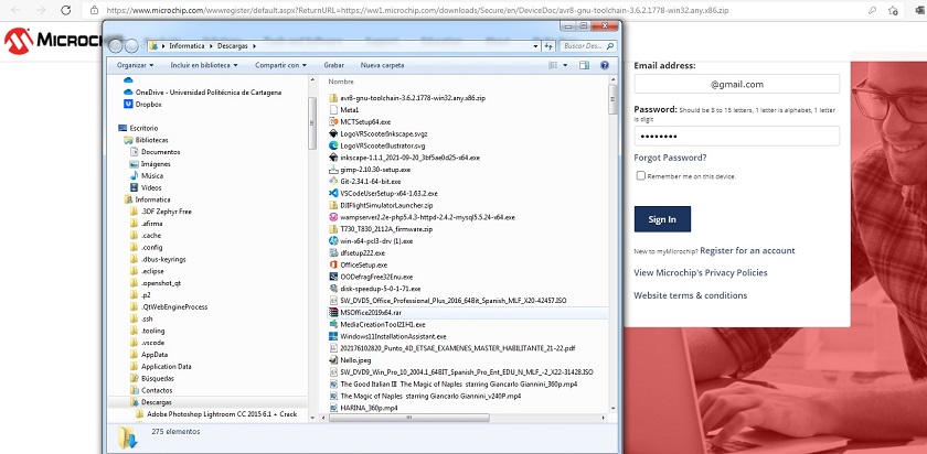 Download software Atmel GNU Toolchain
After installing the GNU Make software. This was the easiest to install.
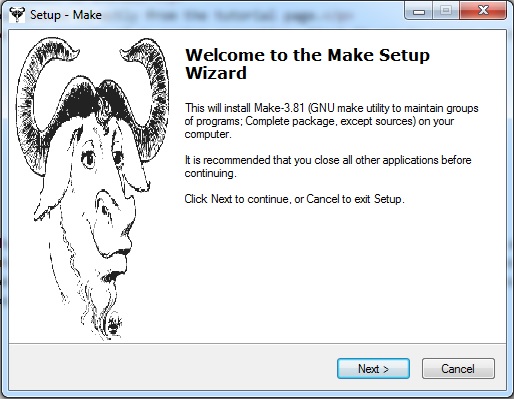 Installing gnumake
Another software to install was the avrdude that I downloaded directly from the tutorial page.
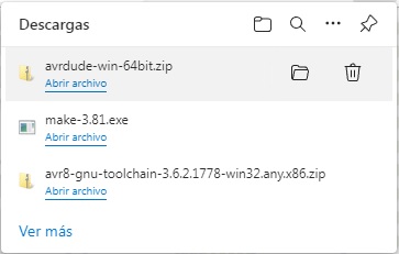 Download software avrdude
Now, before installing more software, I had to change some aspects of my system properties. First it was to access system preferences, go to system properties and enter in Environment Variables some paths in the computer.
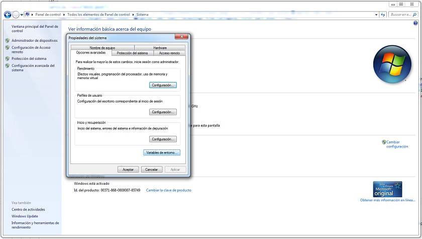 Introducing new paths in environment variables
- C:\Program Files\avr8-gnu-toolchain-win32_x86\bin
- C:\Program Files (x86)\GnuWin32\bin
- C:\Program Files\avrdude
Finally I must install the drivers for my programmer. To perform this operation I must download and install the Zadig software. If you want the new link address, you can download them from here.
After having performed the above operations, I just have to check that everything is working. For this purpose, I must write some commands in the GIT BUSH console.
- make -v
- avr-gcc --version
- Connect your programmer to a USB port and type: avrdude -c usbtiny -p t45 and press enter
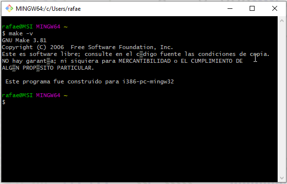 make -v
avr-gcc --version
make -v
avr-gcc --version
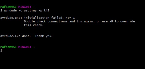 Connect your programmer to a USB port and type: avrdude -c usbtiny -p t45
 Connect your programmer to a USB port and type: avrdude -c usbtiny -p t45
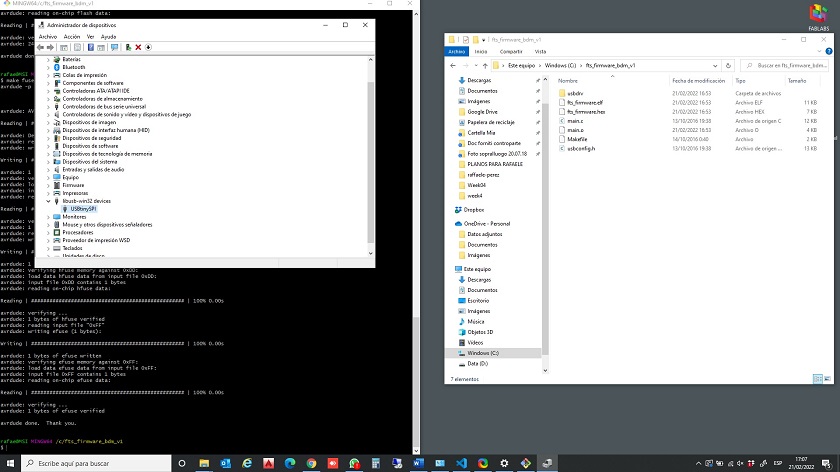
Once I have downloaded the programmer drivers, I connect the board to the usb and go to device manager. The controller appears and without problems, the electric plate is ready.
 Boards almost finished
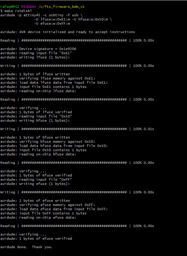
Check the fts firmware.hex file, to do so I change the extension and edit it with notepad.
Finally I will leave an image where you can see the two connected developers.
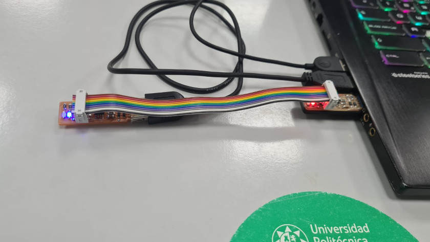 Programming from the old to the new
WORKING WITH ARDUINO
After I have installed the Arduino, I have to follow a few steps to get my programmer up and running. The first step is to install in the Arduino environment the type of processor of my electronic board.
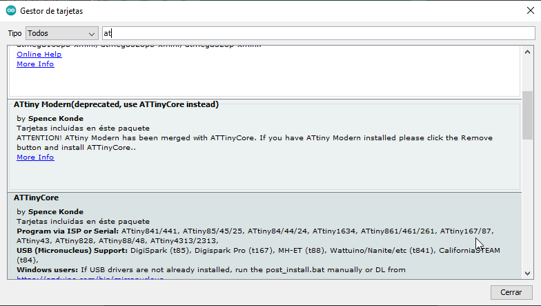 Programming card components
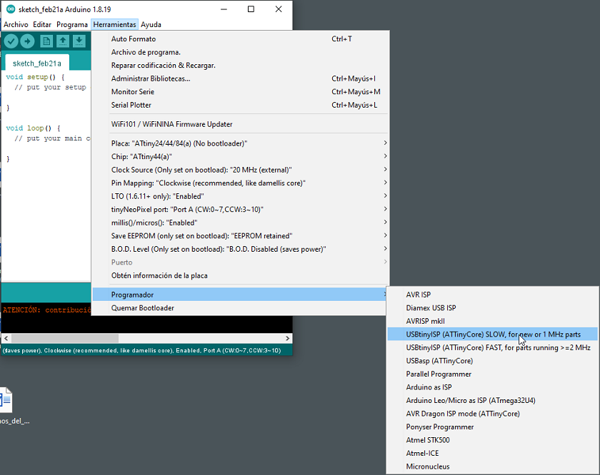
After having installed the components so that the arduino recognizes the processor, we have to set some parameters so that the Arduino is able to recognize the board.
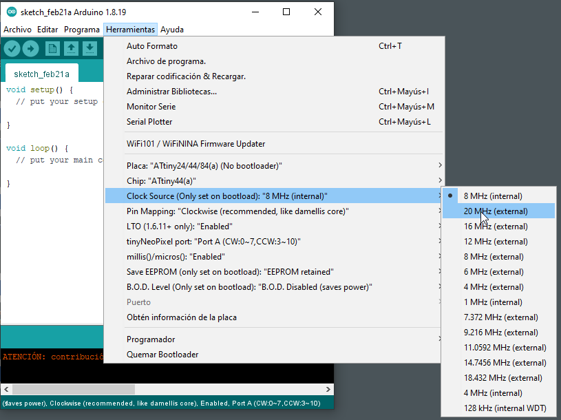 checking parameters
 checking parameters
At the end, we look for an example already pre-installed in arduino and we modify the parameters. In my case, it was to modify the blinking speed of the LED light that we lowered from 1000 to 500 to make it faster.
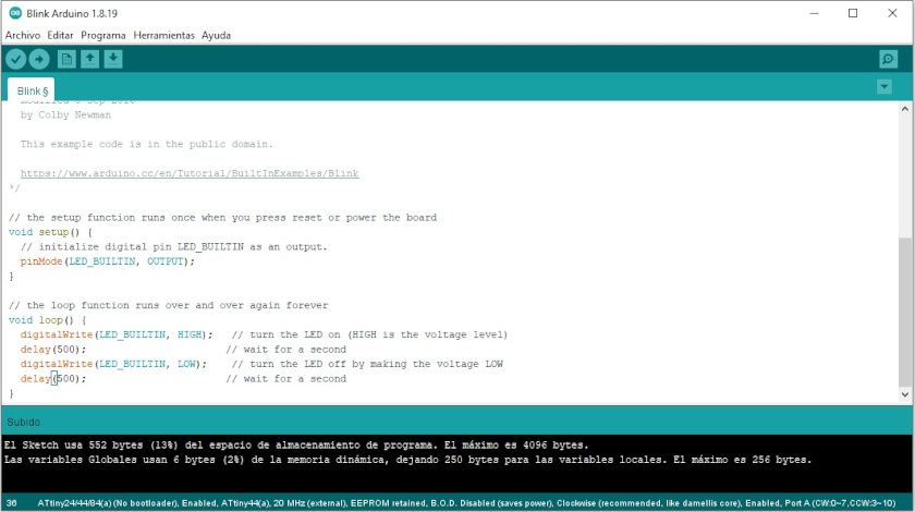 Programming in Arduino
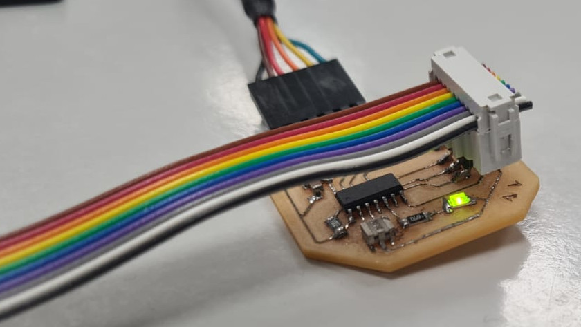 Programmed license plate led light
CONCLUSIONS OF THE WEEK
This week has been very complicated for me, I have gone from doing one task per week to two. Unfortunately I am alone and it is difficult to do individual and group work, but I think I have achieved it..
I really liked working with wood and making parametric models. Another thing that I liked is making the wood flexible with the design. There are an infinity of patterns and I would like to continue experimenting because it has a very nice design component.
It has also been very useful for me to experiment with the laser cutter, knowing these machines in depth helps to exceed the limits to improve manufacturing.
Well I hope that next week will be easier although I think it will not be like that.
MY FILES
All files used are available with direct download links.


