WEEK 03
ON THIS PAGE WE WILL FIND AN EXPLANATION OF THE DEVELOPMENT OF MY WORK THROUGHOUT THE THIRD WEEK
GENERALITIES
This week we had to work skills with "computer controlled cutting". More specifically, the work has focused on parametric design to then learn to manufacture with some of the most used machinery of a fablabs. Of course, to be able to work with these machines you have to know them in depth. For this, calibration and characterization tasks have been carried out on the devices with different materials.
In the end, CAD and CAM manufacturing work has been required. Software such as Fusion 360, which is capable of making three-dimensional parametric models, and AutoCAD, which is a well-developed software for 2D parametric work, have been used for CAD manufacturing.
| Day | Wenesday | Thursday | Friday | Saturday | Sunday | Monday | Tuesday |
|---|---|---|---|---|---|---|---|
| 09:00 | |||||||
| 10:00 | Meeting CT | Assigments | Assigments | Local Review | |||
| 11:00 | Meeting CT | Assigments | Assigments | Local Review | |||
| 12:00 | Assigments | Assigments | |||||
| 13:00 | Assigments | Assigments | Regional Review | ||||
| 14:00 | Assigments | Assigments | Regional Review | ||||
| 15:00 | Fabacademy | Practice | Practice | ||||
| 16:00 | Fabacademy | Practice | Practice | write Documents | Review Documents | ||
| 17:00 | Fabacademy | Practice | Practice | Assigments | Assigments | write Documents | Review Documents |
| 18:00 | Fabacademy | Practice | Practice | Assigments | Assigments | write Documents | Review Documents |
| 19:00 | Practice | Practice | Assigments | Assigments | write Documents | Review Documents | |
| 20:00 | |||||||
| 21:00 | Tutorial | Tutorial | Assigments | Assigments | Assigments | write Documents | |
| 22:00 | Tutorial | Tutorial | Assigments | Assigments | Assigments | write Documents | Write Documents |
| 23:00 | Tutorial | Tutorial | Assigments | Tutorial | Write Documents | ||
| 24:00 | Tutorial | Tutorial | Assigments | Tutorial | |||
| 01:00 | |||||||
| 02:00 |
PARAMETERIZE WITH FUSION 360
To begin with, as I have worked very little with fusion 360, I was looking at some tutorials to understand its parametric operation in three dimensions. I have been working with autocad for years and for me it is very difficult to make the leap.
It must be recognized that this software is very complete and is optimal for working parameterizing in 3 dimensions and not only. It has a number of tools that make it useful for showing the process of building a model.
I have used the following tutorial to understand how it works.
I was building a parametric model step by step. Here are some screenshots.
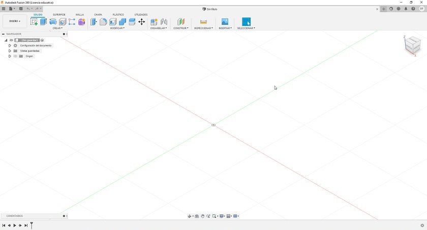 Step 1: We open the software and save the project
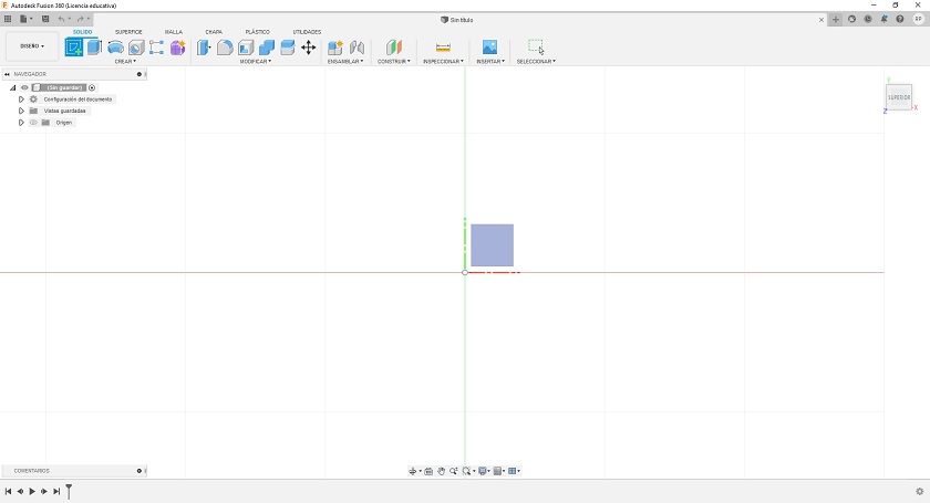 Step 2: We establish the construction plane of the sketch
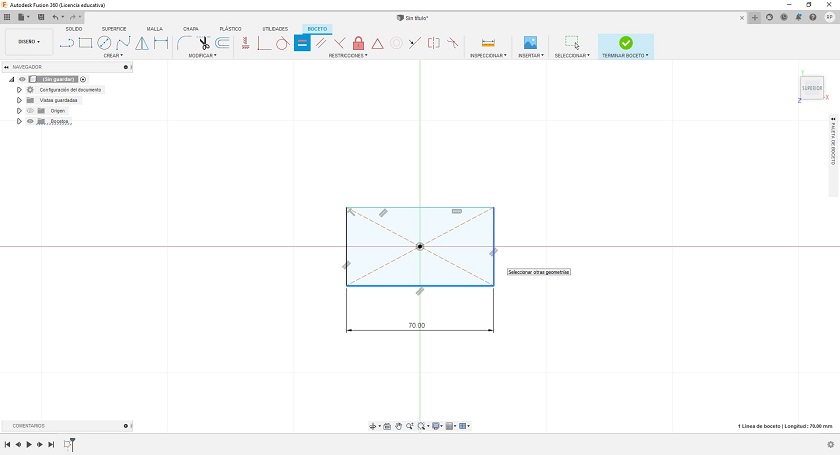 Step 3: Work on the plan sketch and establish the elevation parameters
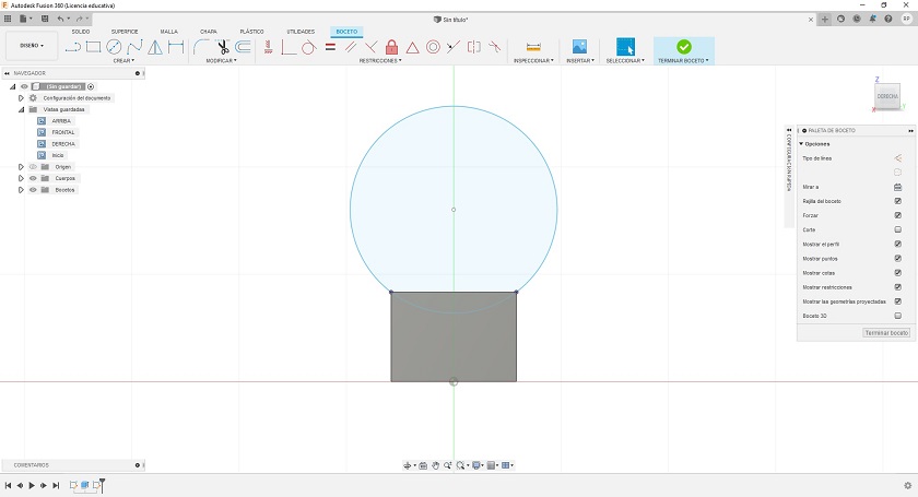 Step 4: Then we go to the vertical parametric plane
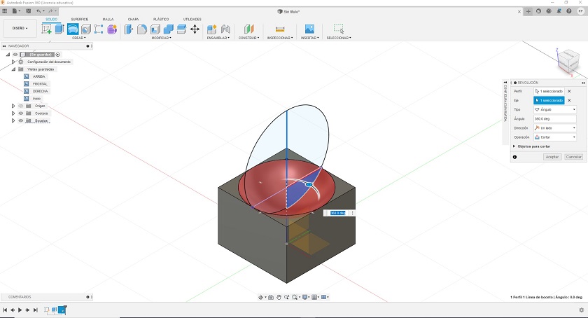 Step 5: We make a revolution to empty the sphere into the box
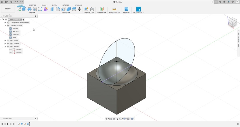 Step 6: We build the sphere
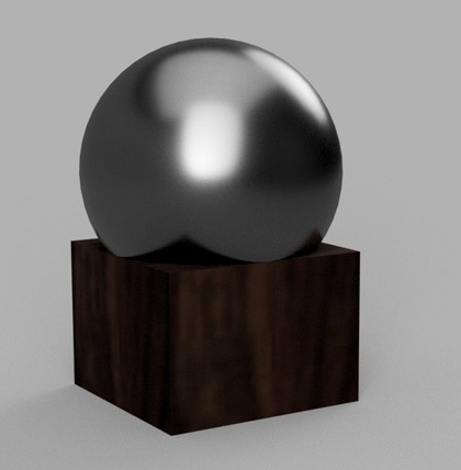
Here I am going to leave a render so that the finish of the solids can be appreciated.
Now I am going to give a few more explanations about how a drawing can or should be parameterized. Fusion 3D is a tool with many facilities on parameterization.
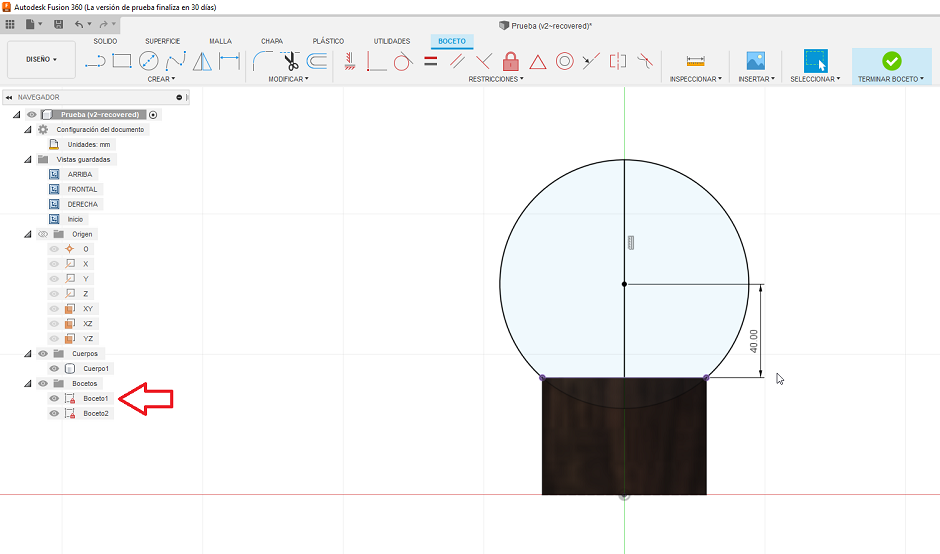
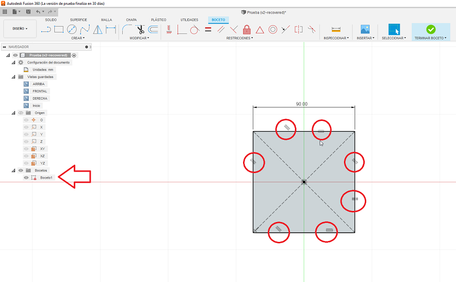
In the bar on the left there is a menu with all the steps for the elaboration of the design. To obtain modifiable parameters, some parameters have been elaborated on sketches. These coroquis are editable and at the moment they are edited, the 3D drawing changes.
Add that in the elevation two contact points have been imposed that do not distort the figure in the event that the measurements of the elements that make up the figure change.
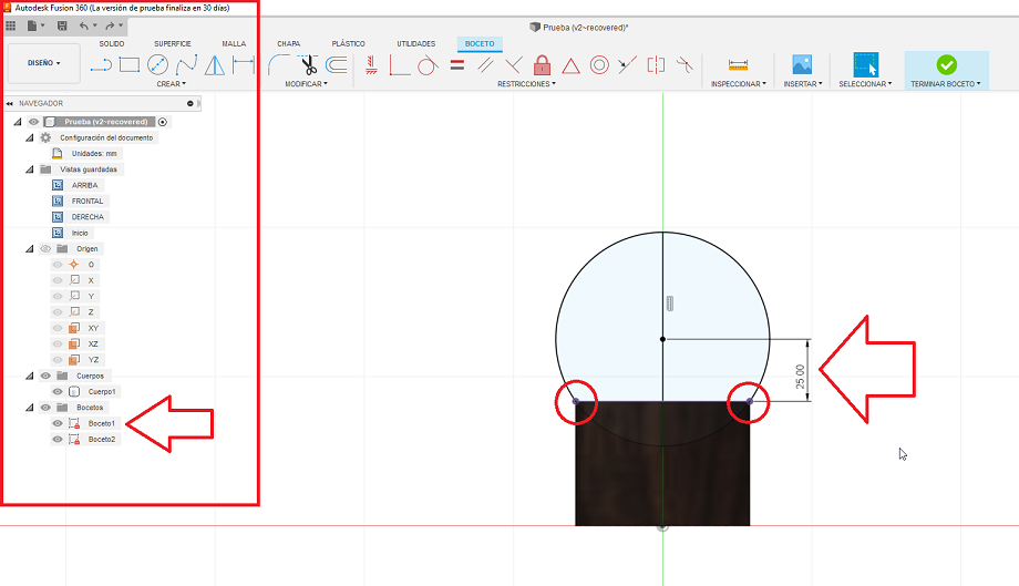
Clicking on the sketch does not open the sketch window where some dimensions have been established that I am going to edit so that you can see how the image changes.
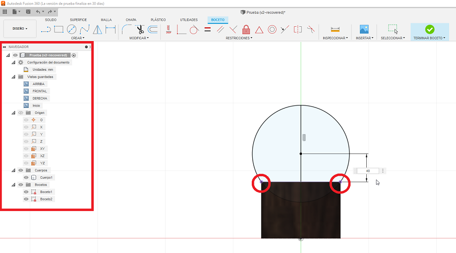
The sphere after having gone from 25 to 40 mm has become larger.
While we're at it, I'm also going to change the size of the base, as we can see from the initial drawing, the cube has a width of 700 mm plus a few parallelism and perpendicularity parameters. Like the previous example, I click on the dimension and transform it.
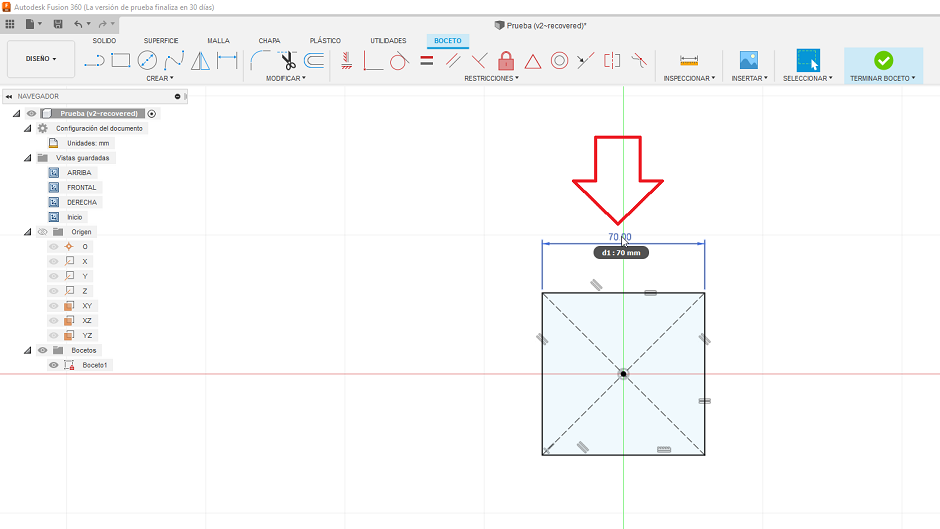
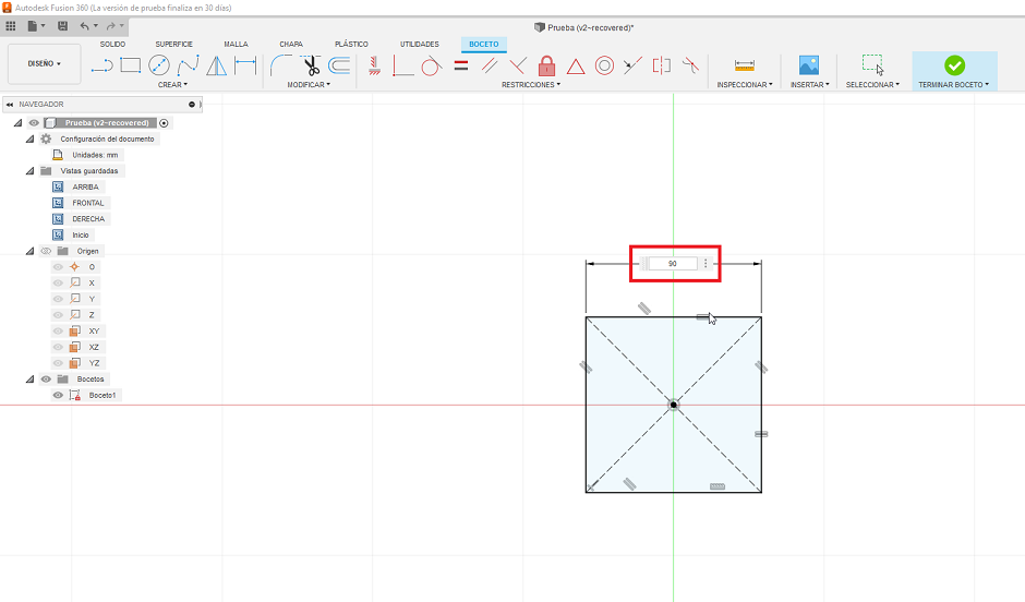
We already have our rectangle of 90 mm width and height, due to the conditions imposed in the drawing.
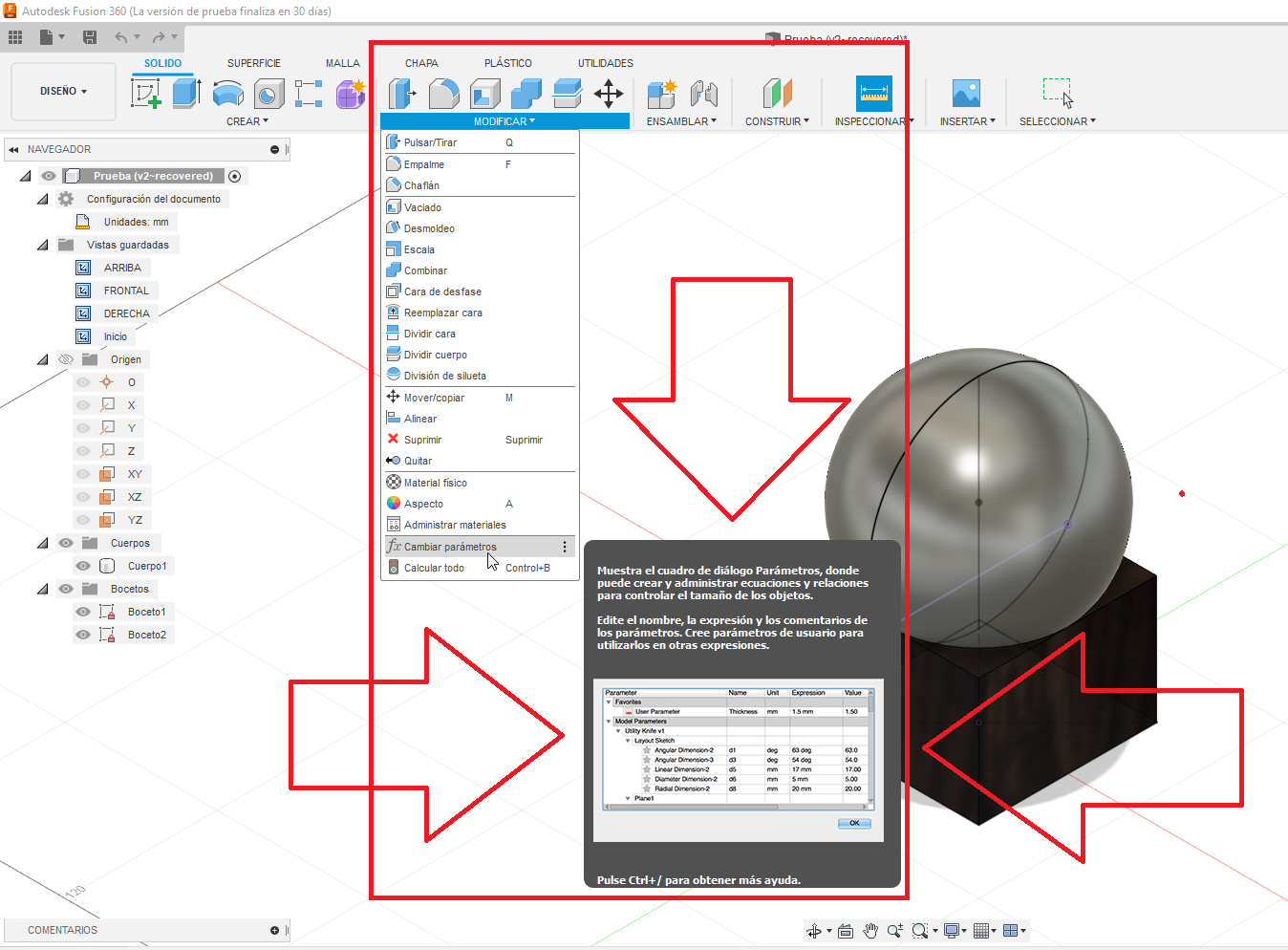
Another more fun way to work parametrically is to use the table of parameters found by looking for it in the modify menu and in the submenu modify parameters.
I will leave a video with the parts for the composition of the drawing
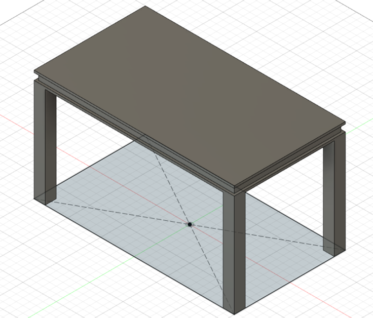
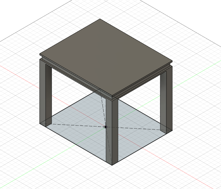
After having done the tutorial, this time I am going to make an example of my own. In this case I am going to model a dining table with a constraint in the XY plane. To do it I have to make a sketch. In this case I can modify the dimensions in the drawing as I wish.
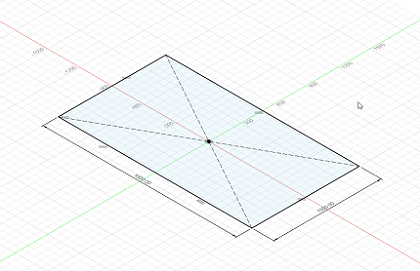
 Before: Original measurement
 After: Measures modified
I will leave a video with the parts for the composition of the drawing
In addition to the work described above, other types of work with parametric structures have been carried out. Shear tests have been carried out to establish the relationship between gedesic structures and others assembled with the cuttings inside. This is because the spheres are parametric figures where the function that generates them has the same relationship between the parameters.
I will leave a video with the parts for the composition of the drawing
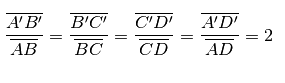
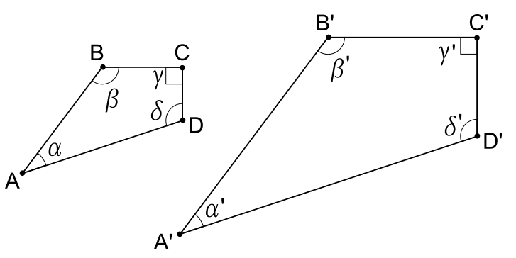
Similar polygons
We start from the definition: due polygons F and F1 with the same number of Latin if similar label is possible because of biunivocal correspondence and vertices of F with i vertices of F1
- The consecutive vertices of F correspond to the consecutive vertices of F1
- The corresponding angles are congruent
- The ratio between the measures of the homologous sides is constant, where homologous sides are meant the pairs of sides including the corresponding vertices.
More briefly, two similar polygons have neatly equal angles and the sides between them in proportion
In the following image you can see an example of similar polygons, where we have depicted two quadrilaterals such as to have neatly congruent angles
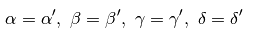
Sides proportional to each other. indeed
That the projection of figures in space on the plane have the same characteristics, I am going to leave the photo of a geodesic figure.
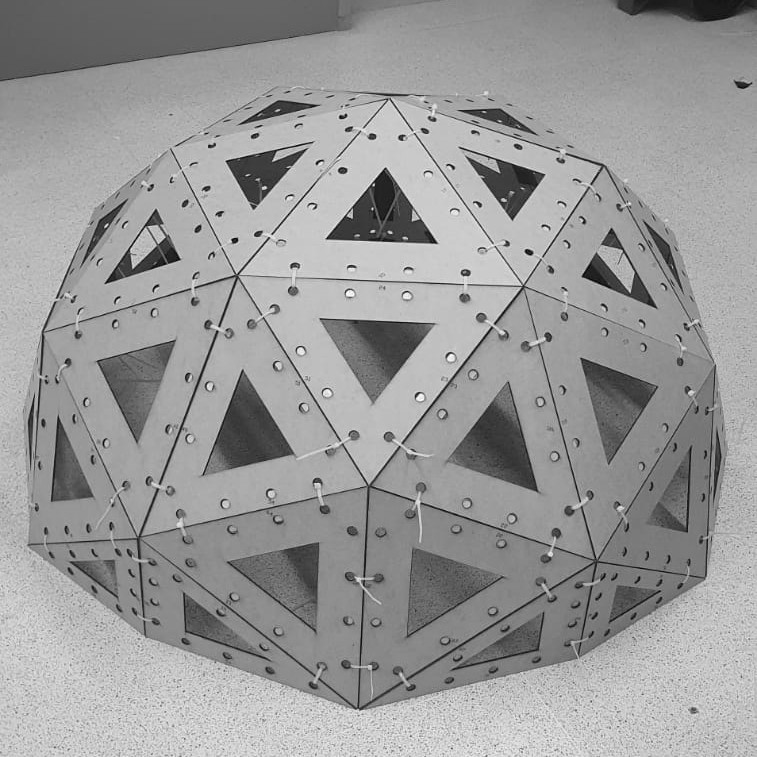 Outer sphere cut and mounted
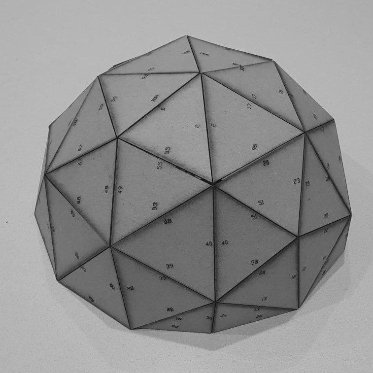 Resulting from the assembled outer sphere
After having seen the results obtained with the sphere, I have gone on to build a parametric Christmas ball. The idea is that it can be expanded but that the restrictions are kept so that once it is scaled, all the measures to be able to mount it are preserved.
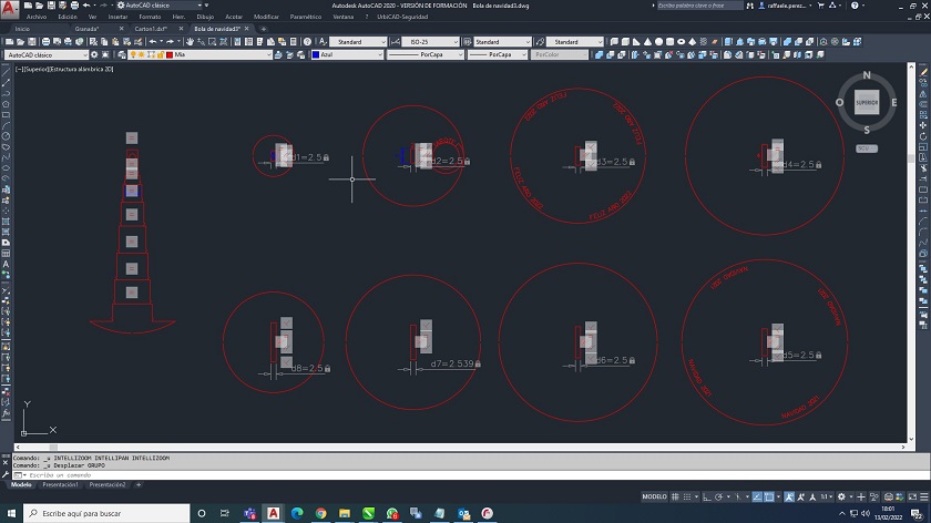 Parametric drawing of the Christmas ball
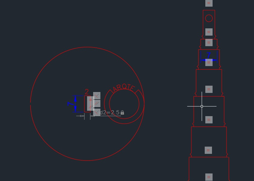 Drawing before being modified
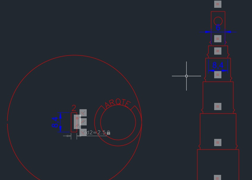 Drawing after being modified
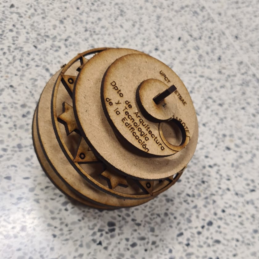
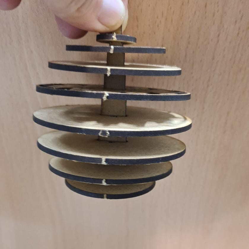
After having finished the drawing I have gone to production, and here I leave some images of the results obtained.
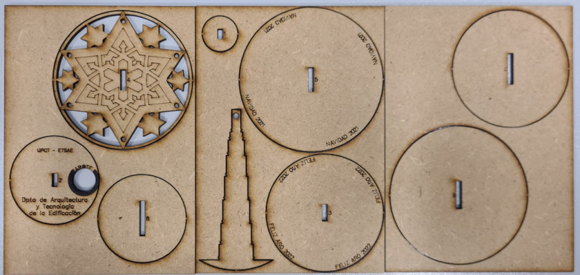 Christmas ball before being assembled
 Drawing before being modified
 Drawing after being modified
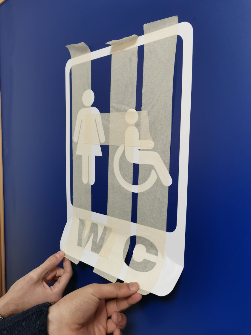
CUT LOGO ON THE VINYLCUTTER DESIGN
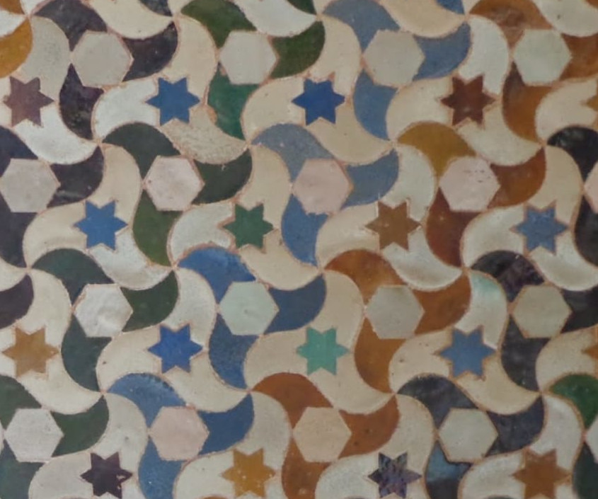
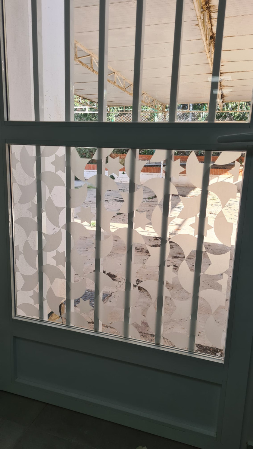
Another job this week was vinyl cutting. My instructor Lola Ojada suggested that she make a vinyl print and then apply it to the Fablab bathroom window.
She suggested that she use a pattern similar to the mosaics in Granada.
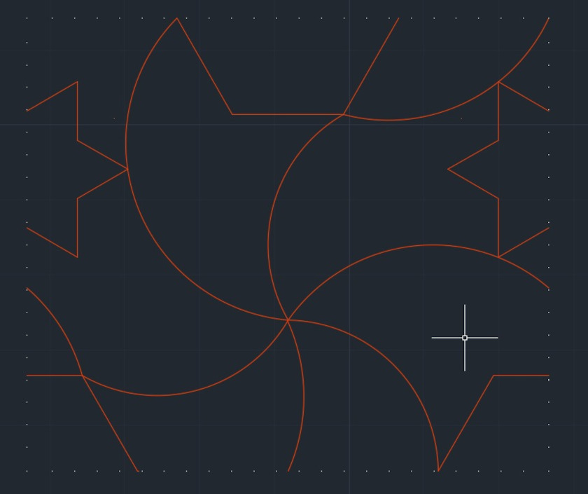
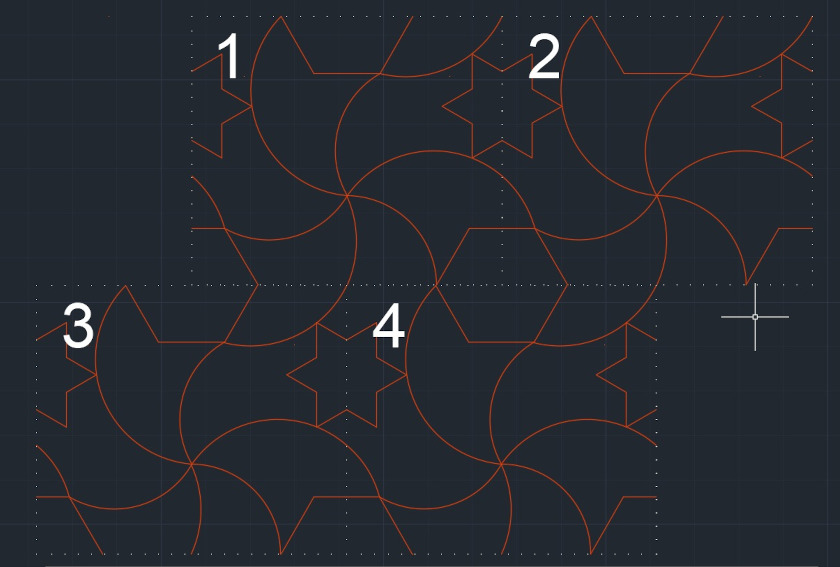
The first step was to choose the type of drawing, once chosen, I was investigating to replicate the geometric pattern of the drawing to compose the design.
 Step 1: We open the software and save the project
 Step 2: We establish the construction plane of the sketch
 Step 3: Work on the plan sketch and establish the elevation parameters
 Step 4: Then we go to the vertical parametric plane
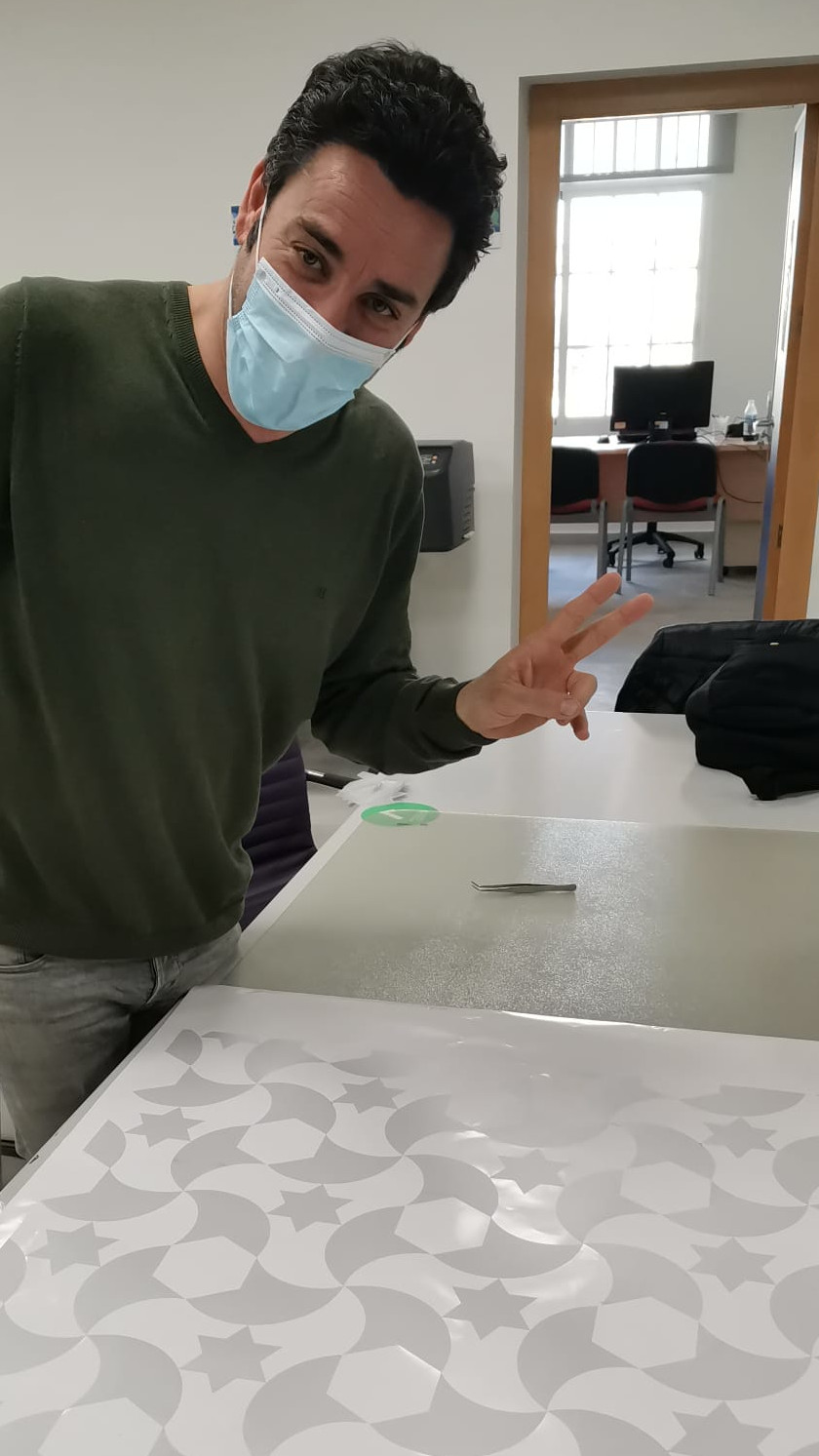
Well, in the end he uses the vinyl plotter to make the print. Since the drawing was very small, it was really difficult to transfer the print to the window.
To carry out the work I used the Great Cut 3 software, if you want download the software, click here
Actually it is very easy to use, anyway if you are interested in using it, I will leave you a link on youtube, for more information, please click here
however, I am going to describe the steps used to get the job done.
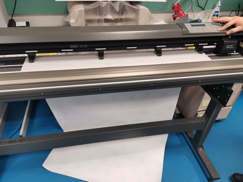
First step load the cut vinyl in the cutting plotter and have the plotter measure the vinyl.
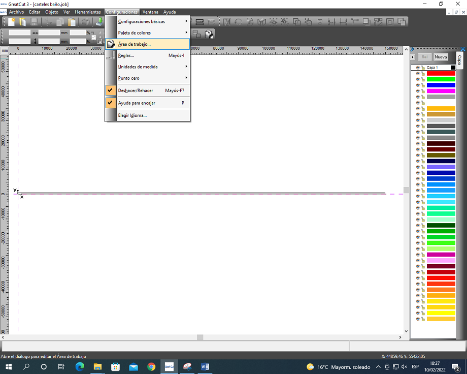
Run the Great Cut program and first configure the work area, making the program take the reading of the material measured by the cutting plotter to ensure that the design does not go out of format
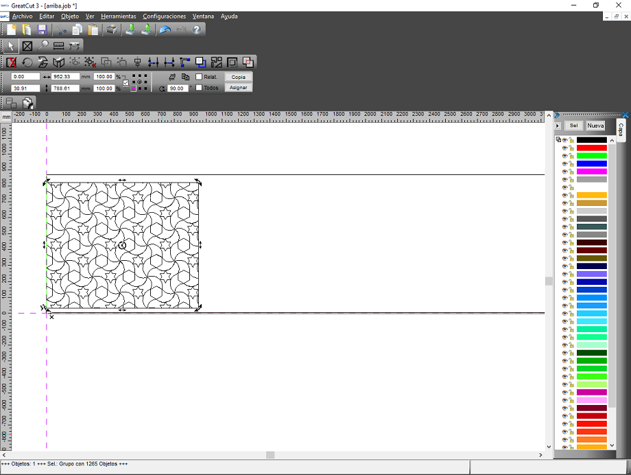
Once the vector lines of the design have been inserted, they are oriented, scaled and positioned in the area of the work area where they want to be cut.
As the design to be made is only for cutting, the vector lines must be imported.
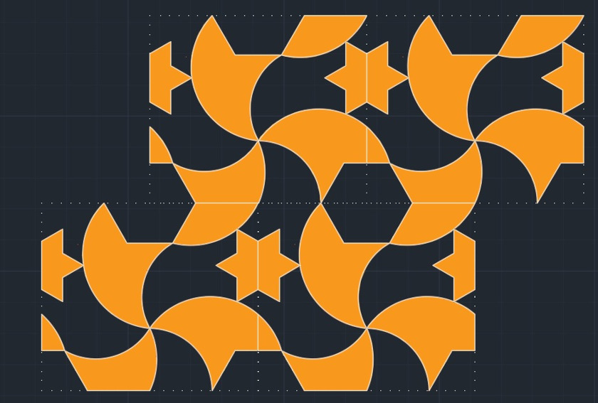
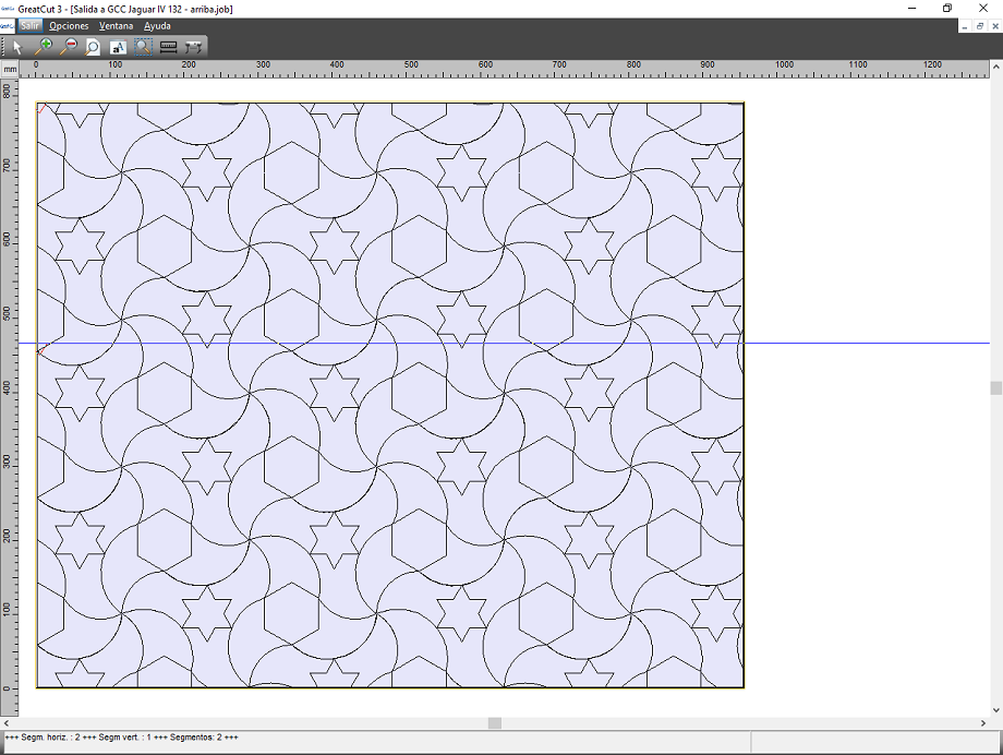
Positioned, we proceed with the preview to verify that the size of the design to be cut is perfectly adjusted to the dimensions of the vinyl placed on the cutting plotter.
In the event that Great Cut 3 detects that the design to be cut is larger than the vinyl, Great Cut 3 sections it to make it in the number of cuts it deems convenient.
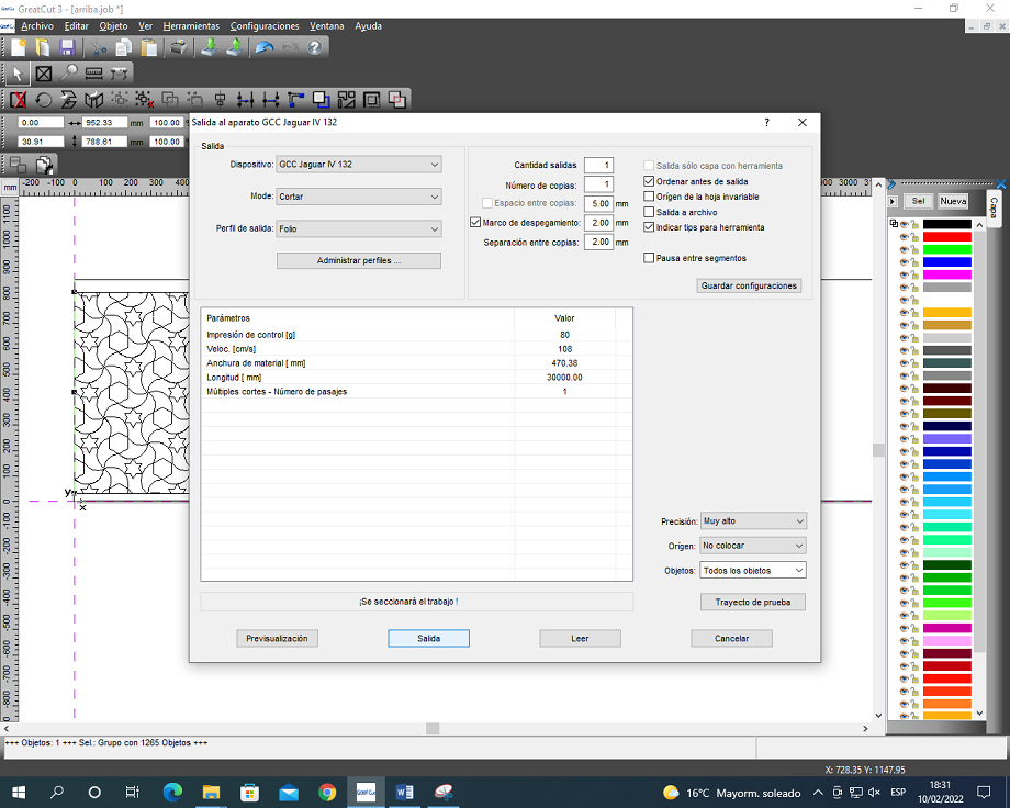
Verified, the job is launched, for this the force of the blade, the speed and the number of passes must be configured.
For the type of vinyl used, known as acid-etched vinyl, a speed of 120 cm/s with an Out of 100 has been used. It is only necessary to make one pass with this material.
In order to work with the vinyl machine I have consulted the parameters of the data sheet, if you want download the datasheet, click here
The work has been done with a Juagar IV vinyl plotter
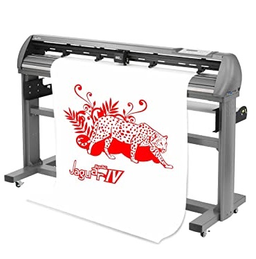
I will leave the most important data
| operating method | Max. cutting width | Max. Media loading width | Min. Media Loading Width | Number of pinch rollers | Max. paper thickness | Handle | Max. Cutting force | Max. shear rate | Acceleration | Make up for | memory size |
|---|---|---|---|---|---|---|---|---|---|---|---|
| roller type | 1320 mm (52 “) | 1594 mm (62,8 “) | 50 mm(1,97 “) | 4 | 0.8mm (0.03 inches) | Servocontrol DC | 600 grams | 1530 mm / sec (60 ips) | 3G (gravity) | 0 ~ 1.0mm (with an increase of 0.025mm) | 4 MB |
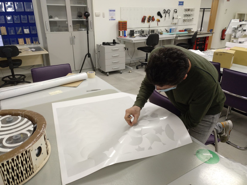
After having obtained the print job, I will move on to the paste operations.
 Step 5: We make a revolution to empty the sphere into the box
 Step 6: We build the sphere
In the images below you can see the work done.
 Before: Original measurement
 After: Measures modified
In addition to the work described above, other types of vinyl cutting work have been carried out.
 Outer sphere cut and mounted
 Resulting from the assembled outer sphere
FLEXIBLE CUT
In the next job this week, I have been testing the materials to make them flexible. I was curious to know which of the materials was the most suitable for the construction of my lamp. In the final project I would like to build, the outer skin is flexible wood. I have been researching on the internet the patterns that best fit my objective and in the end I have made some samples.
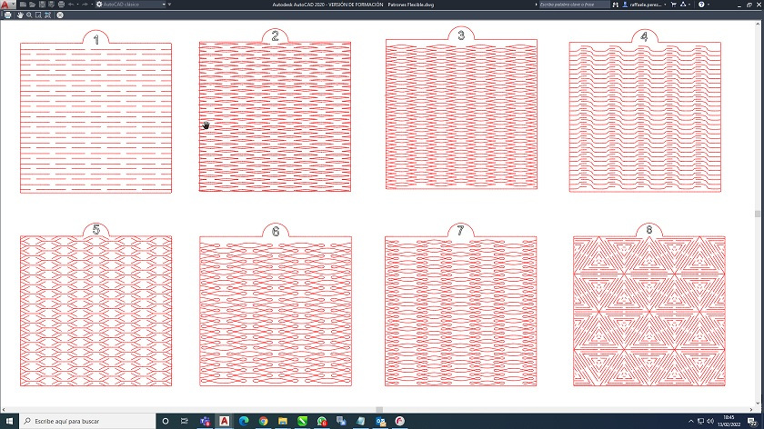 Selected Flexible Wood Patterns
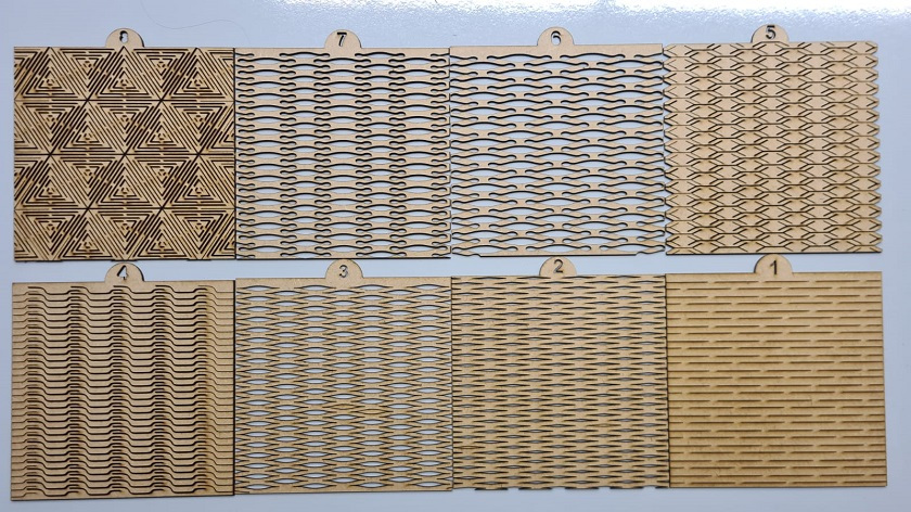 Manufactured Flexible Wood Patterns
Among the patterns that have been made, there are some that fold in one direction and others that fold in two directions. I leave here below some photos of what I think are the most adjusted to the manufacture of the outer layer of the lamp.
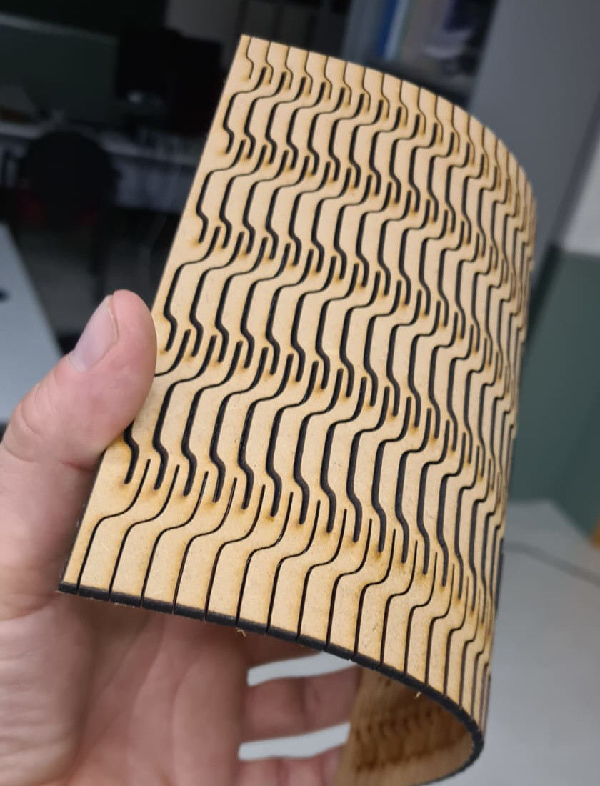 Folded in one direction
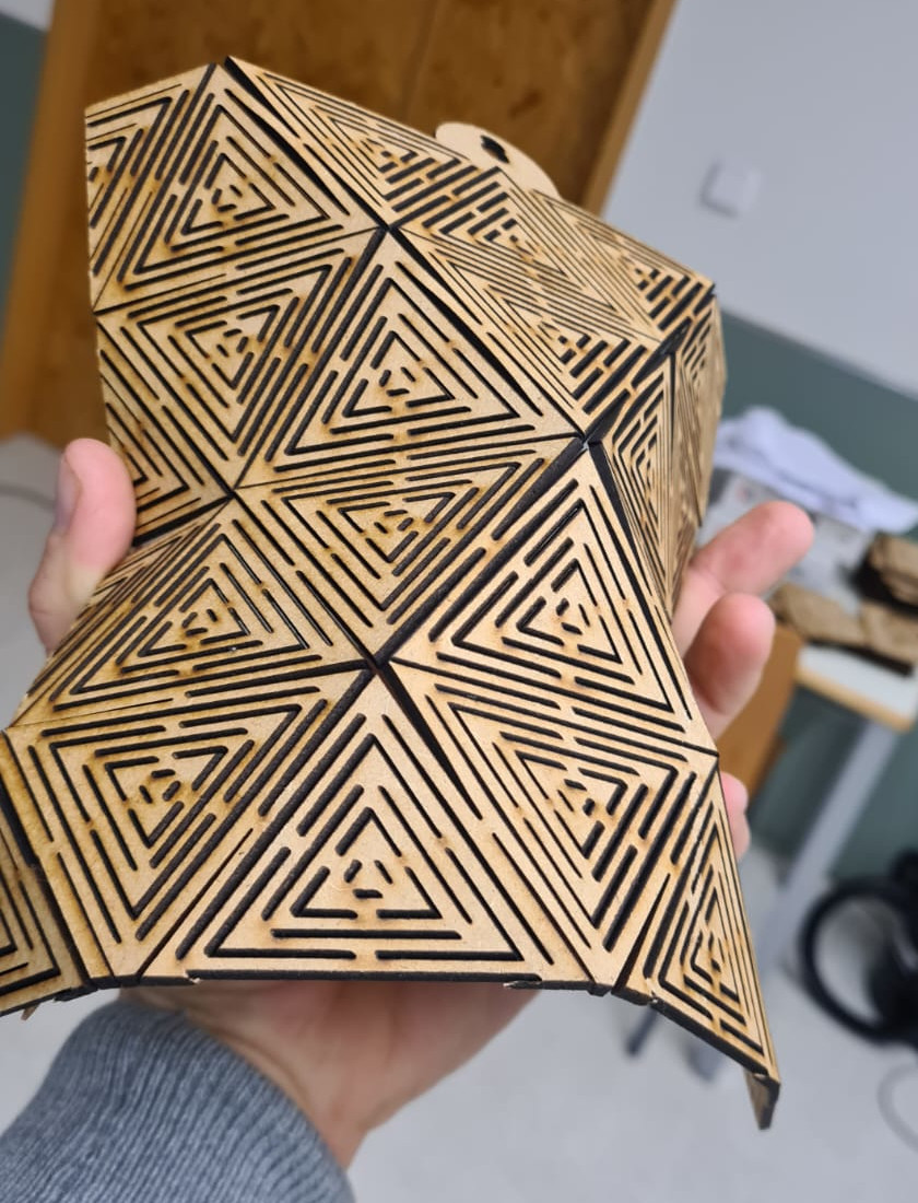 Folded in two directions
CONCLUSIONS OF THE WEEK
This week has been very complicated for me, I have gone from doing one task per week to two. Unfortunately I am alone and it is difficult to do individual and group work, but I think I have achieved it..
I really liked working with wood and making parametric models. Another thing that I liked is making the wood flexible with the design. There are an infinity of patterns and I would like to continue experimenting because it has a very nice design component.
It has also been very useful for me to experiment with the laser cutter, knowing these machines in depth helps to exceed the limits to improve manufacturing.
Well I hope that next week will be easier although I think it will not be like that.
MY FILES
Here I am uploading the files that I have been making this week
Main parts of this document
-
3.1 Introduction
-
3.2 Parametric Construction Process


