Computer-Controlled Cutting
Group Assignment 2022 (Raffaele Alone)
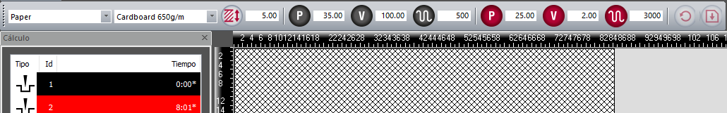
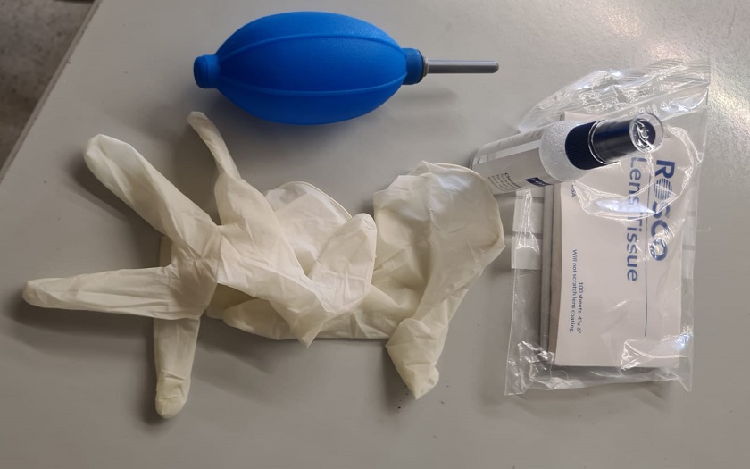
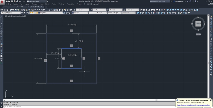
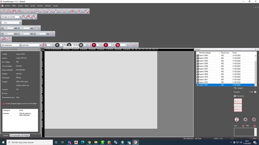
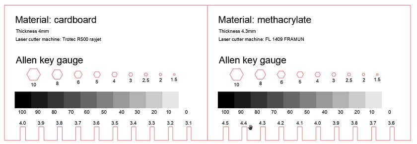
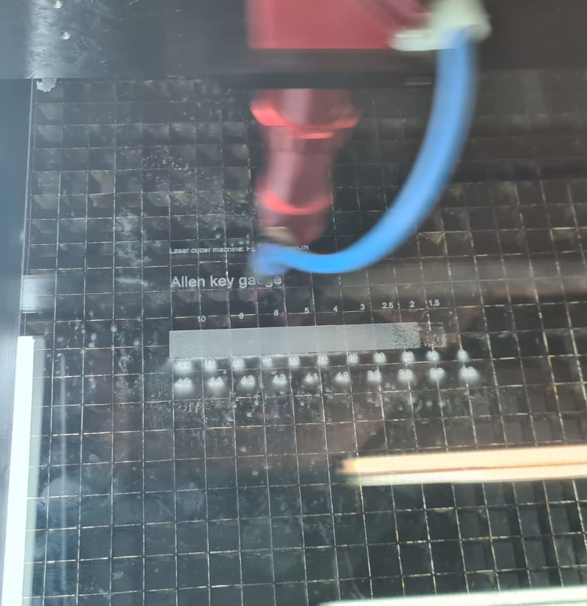
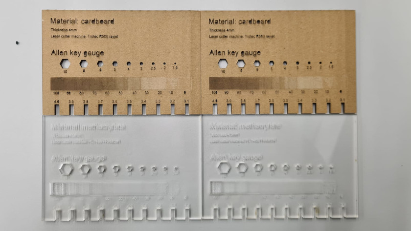
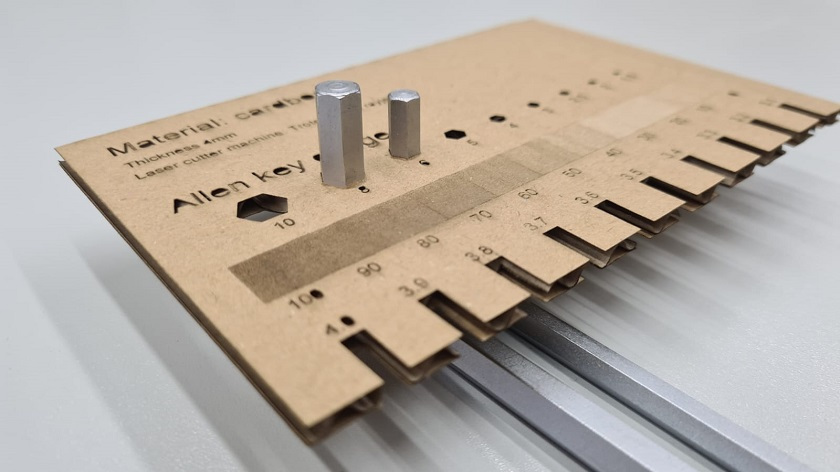
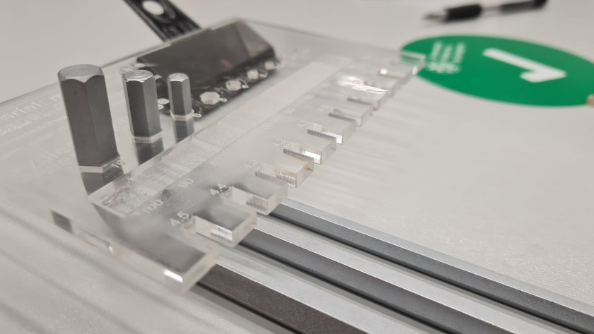
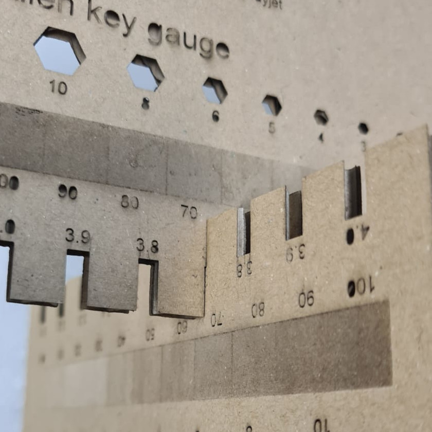
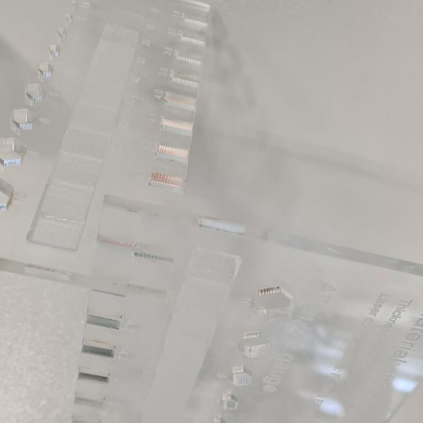
The group work has been carried out with the r500 laser cutter from the To be able to cut the materials I have used the parameters that the software has by default and they have worked perfectly for me. I will leave some screenshots. Laser cutting is a technique used to cut sheet metal parts characterized in that its energy source is a laser that concentrates light on the work surface. To be able to evacuate the cut material, it is necessary to supply a pressurized gas such as oxygen, nitrogen or argon. It is especially suitable for pre-cutting and for trimming excess material, being able to develop difficult contours in the pieces. Among the main advantages of this type of part manufacturing, it can be mentioned that it is not necessary to have cutting dies and to allow silhouette adjustments. Also among its advantages it can be mentioned that the drive is robotic in order to keep the distance between the electrode and the outer surface of the part constant. Due to the high energy levels available at low cost, laser cutting is the perfect method for the production of handcrafted artifacts and industrial prototypes. It is also perfect in the field of architecture in the CAM digital manufacturing process for corrections in educational classrooms. Power parameter The Trotec R500 is a laser cutting machine that offers power parameters for both cutting and engraving that range from 1 to 100%. It usually works in 2 layers, one for cutting and one for engraving. For the characterization work of the machine, a study has been carried out based on the color layers for engraving and a calibration for cutting. Velocity parameter From the specifications in the table above, we know that the speed of it is 1m per second. For engraving, another fundamental factor is speed, since at the same power with a lower speed, deeper cuts are achieved. Before proceeding to carry out the work we have cleaned the lenses. The objective was to adjust all possible parameters in order to achieve an optimal characterization of the machine. To clean the lens, a special detergent for lenses and foil have been used to remove dirt. Drying has been done with a manual air pump. The following photos show the dirt on the lens and after cleaning it. To use the laser cutter we can use any CAD or vector image editing program. We can also print it from an image editor. To carry out our task, we send to print directly from Autocad. In this case, a test has been done to calculate the material that the laser eats. The drawing that has been made is parametric. To calculate the kerf parameter we draw two concentric squares (20mm the smaller, and 50mm the bigger). To send it to the cutter, everything works as if it were just another printer. Just check a few parameters and you're good to go. I leave some screenshots. The laser cutter management software will open where we will check the printing parameters. In this case, a test has been done to calculate the material that the laser eats. The drawing that has been made is parametric. To calculate the kerf parameter we draw two concentric squares (20mm the smaller, and 50mm the bigger). To send it to the cutter, everything works as if it were just another printer. Just check a few parameters and you're good to go. I leave some screenshots. Choice of printing mode First we choose the print mode. On the r500 we will use the default color and settings. This is because this cutter uses Red for cutting and Black for engraving. power and speed Very important to have a custom cut is to establish the power and speed. In my case, to calculate the kerf on a cardboard-type material, a power of 40% and 15% speed over 100% have been used. A clean cut with a minimum of material destruction has resulted. Other tests have been carried out and it has been seen that by lowering the power, the cardboard was not sectioned well and by raising the power, the cut was very thick. To calculate the Kerf we will use the values measured in the test: 20mm -> 20mm – 19.59 = 0.41mm 30mm -> 50mm – 49.69mm = 0.31mm 20mm hole -> 20mm – 20.41mm = -0.41mm Kerf= [(0.41+0.41+0.31)/3]/2= 0.18 mm approx. After having calculated the Kerf, we have proceeded to the characterization of the laser cutter by making a meter to visually obtain the waste of material in the laser cut. With the obtained kerf we have made an allen key gauge and it must be added that it works perfectly. I leave here some photos. In order to have an optimal cut, the height of the light flow has been calibrated. Here I leave an image capture while the laser cutter is working to make the cuts. Cardboard has been the most complicated material to test since it has very thin layers and several tests have been carried out to carry out the engraving. After having made the drawing with the Autocad software, the laser cutter is calibrated to have an optimal laser flow height. It must be repeated for both materials since they have different heights. These are both gauges finished and ready to measure. The cardboard was cut with a power of 40% and a speed of 15%. The engraving has been obtained with a power of 60% and a speed of 80% to obtain an optimal result. The methacrylate material has been cut with a power of 100% and a speed of 2% while the engraving has resulted with a power of 100% and a speed of 20%. In both cases a clean cut has been obtained and the Allen keys fit perfectly into your gauge. To finish with the pieces obtained, the kerfs have been recalculated.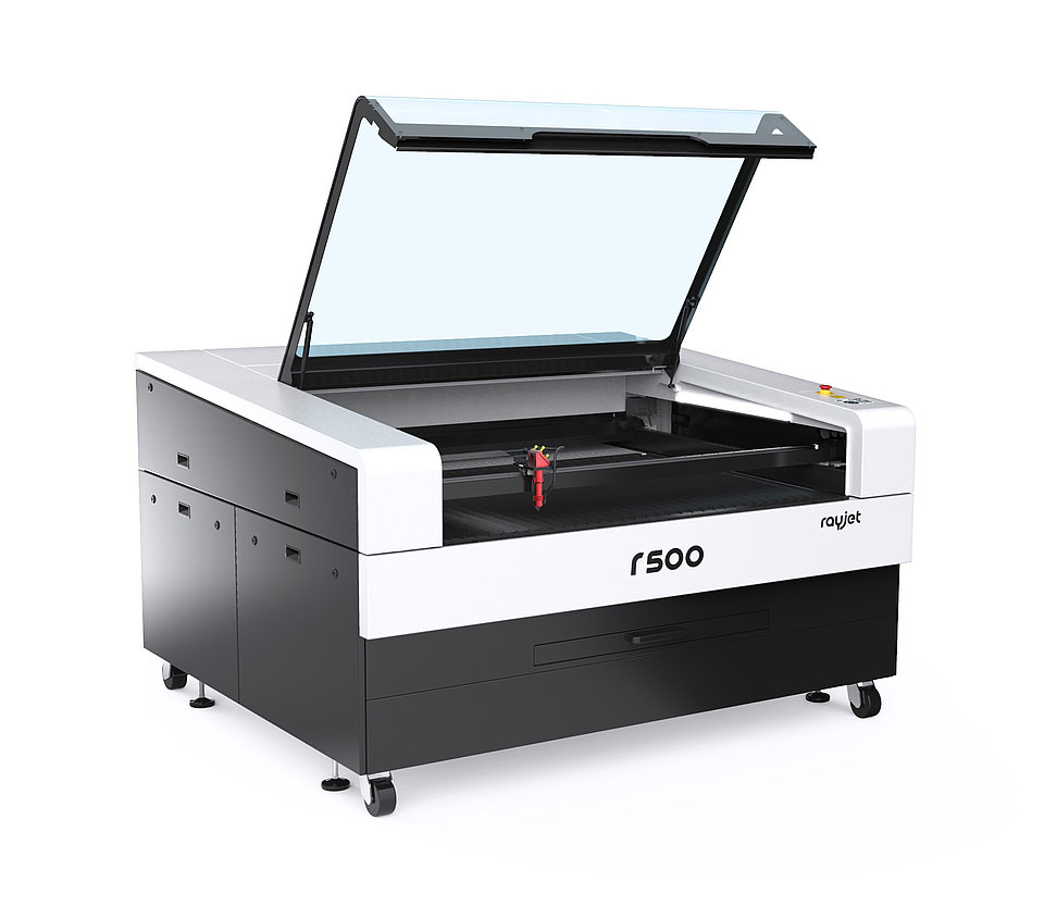
Work Area
Machine Size
Laser Power
Laser Type
Weight: approx.
Cooling system
Max. processing speed
Power consumption laser machine:
Power consumption chiller
Laser Safety
Laser Safety
Laser Safety
Laser Safety:
Laser Safety:
up to 51.1″ x 35.4″
73.5″ x 67″ x 44″
60 – 120 watts
CO2 laser
approx. 1257 lbs
water-cooled
1 m/s
100-250V, 1100-1500W
2500 W
CDRH laser safety
Laser class 2
CE compliant
Double interlock safety system
Kill and key switch
Principals parameters to lassercutting:
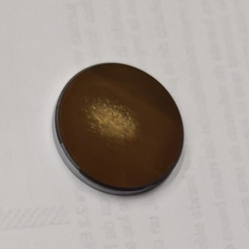 Dirty lens
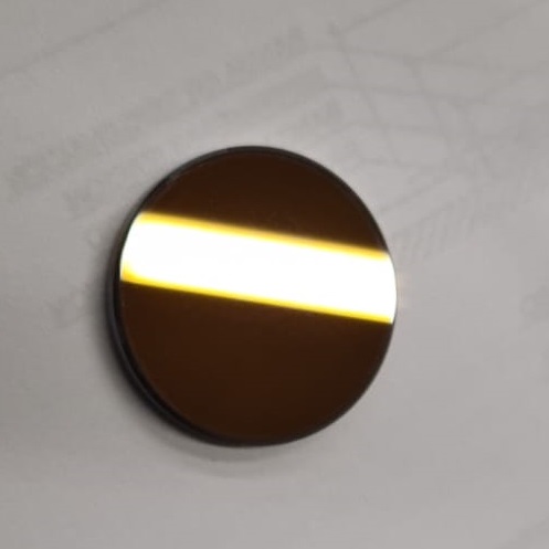 Clean lens
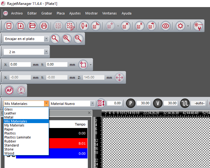
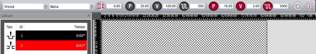
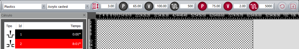
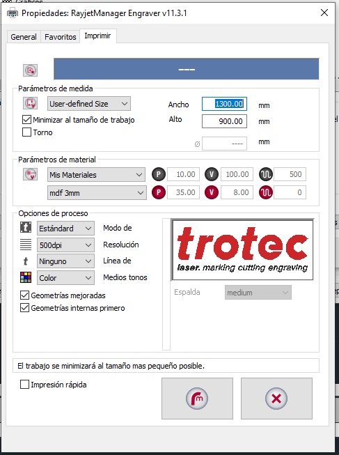 Trotec properties
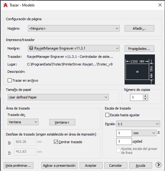 Autocad printing parameters
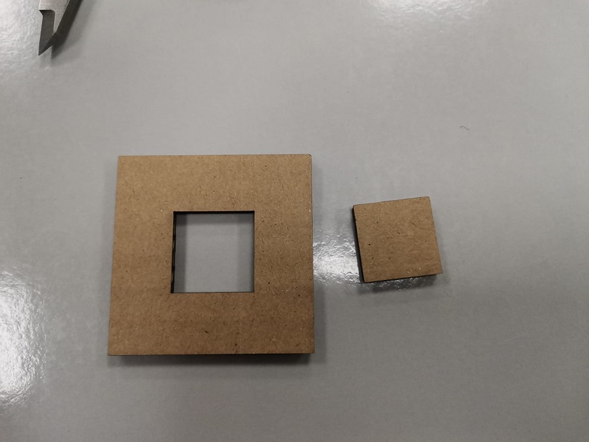 Cut cardboard
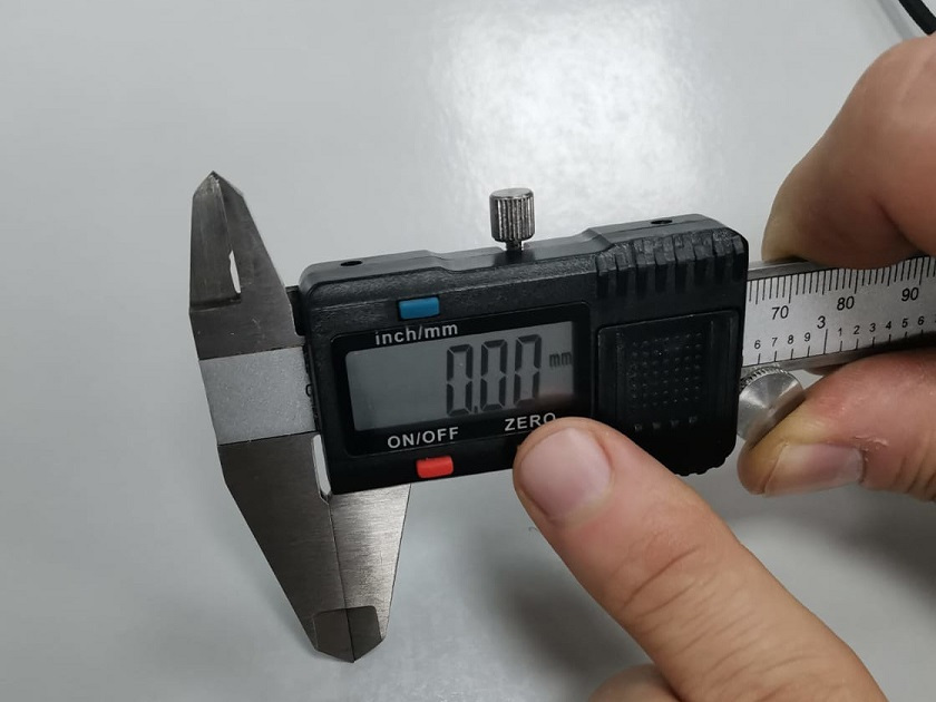 Gauge zeroing
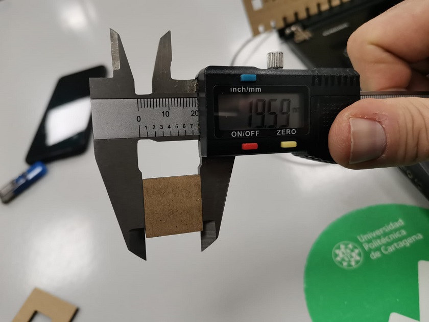 Inner Square Measurement
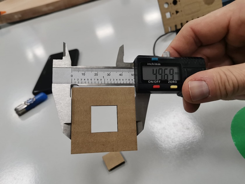 Outside Square Measurement
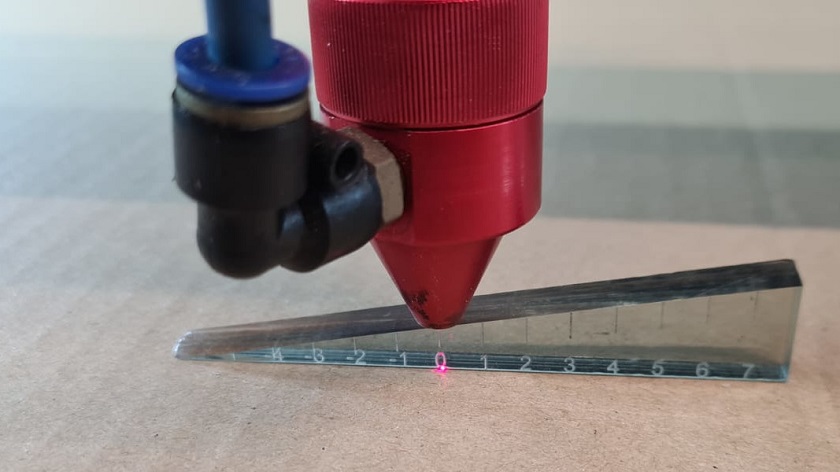 Gauge height for carton material
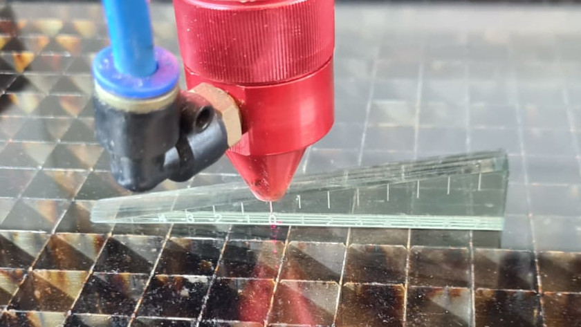 Gauge height for methacrylate material
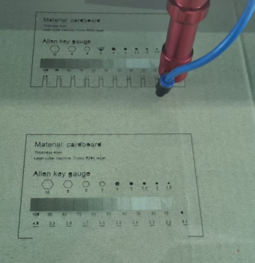 Laser cutting and engraving on cardboard
 Laser cutting and engraving on methacrylate
 Cardboard Meter
 Methacrylate Meter
 lace pieces cut from cardboard
 lace pieces cut with methacrylate