WEEK 02
On this page we will find an explanation of the development of my work throughout the second week
GENERALITIES
This week we had to work skills with "Computer Aided Design". More specifically, in addition to general questions of structure, it was necessary to delve into raster images, learn how to transform an image into a vector, 2D design, 3D design and animation through video.
Really because of my studies and my profession I am used to doing these jobs. My personal goals this week will be, through the use of CAD manufacturing software, to explore the current technical possibilities of this software and to dig a little deeper into my final work to move forward and stay ahead of issues that will arise later.
| Day | Wenesday | Thursday | Friday | Saturday | Sunday | Monday | Tuesday |
|---|---|---|---|---|---|---|---|
| 09:00 | |||||||
| 10:00 | Meeting CT | Assigments | Assigments | Local Review | |||
| 11:00 | Meeting CT | Assigments | Assigments | Local Review | |||
| 12:00 | Assigments | Assigments | |||||
| 13:00 | Assigments | Assigments | Regional Review | ||||
| 14:00 | Assigments | Assigments | Regional Review | ||||
| 15:00 | Fabacademy | ||||||
| 16:00 | Fabacademy | Practice | write Documents | Review Documents | |||
| 17:00 | Fabacademy | Practice | Assigments | Assigments | Assigments | write Documents | Review Documents |
| 18:00 | Fabacademy | Practice | Assigments | Assigments | Assigments | write Documents | Review Documents |
| 19:00 | Practice | Assigments | Assigments | Assigments | write Documents | Review Documents | |
| 20:00 | Assigments | Assigments | Assigments | write Documents | |||
| 21:00 | Assigments | Assigments | Assigments | Assigments | write Documents | ||
| 22:00 | Assigments | write Documents | Write Documents | ||||
| 23:00 | Write Documents | ||||||
| 24:00 | |||||||
| 01:00 | |||||||
| 02:00 |
RASTER
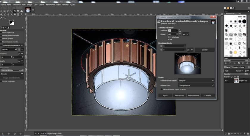
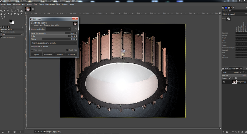
After attending class on Wednesday, I installed the "GIMP" software to work with it. With this software I wanted to accomplish two tasks: first I would edit an image to make it more presentable using the filters pre-installed in the software and then arrange them on my web page, then I would use the software to reduce them to a width of 840px and 96 parts per inch. After this last job I got a file that took up less space and was easier to open in the browser.
To learn more about "GIMP" I was looking at these tutorials. Click here to open the link.
 Lamp position 1
 Lamp position 2
VECTORIZE IMAGES (2D)
The next step was to work with two image editing programs to be able to vectorize. The objective was to vectorize so that the lines were a function and not a space to occupy without the possibility of transformation. For certain aspects it is more interesting to have a vectorial image because it has many advantages.
I used "INKSCAPE" and "ILLUSTRATOR".
To learn more about "INKSCAPE" I was looking at these tutorials. Click here to open the link.
To learn more about "ILLUSTRATOR" I was looking at these tutorials. Click here to open the link.
Then I leave the screenshots of the software and the menu to vectorize. In the repository at the bottom of the page are the zipped files.
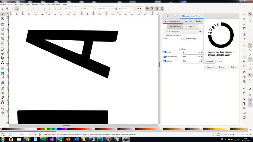 Vectorization made with inkscape software
 Image without vectorization
 Vectorized image
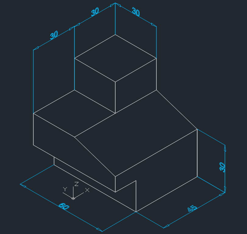
THREE-DIMENSIONAL MODELING
For the three-dimensional modeling I have used Autocad. The choice of this software, although it is not free, is due to the fact that I am working with my work computer and in my work we have acquired Autocad licenses. It must also be said that some free CAD programs have the same graphical environment as Autocad.
The modeling of the lateral supports of the lamp has been solved with the rhino program.
 I have started drawing on the 2D plane in Autocad
 After having made the 2D model I have been working on the 3D models
 Autocad image of the lamp model in position one
 Autocad image of the lamp model in position two
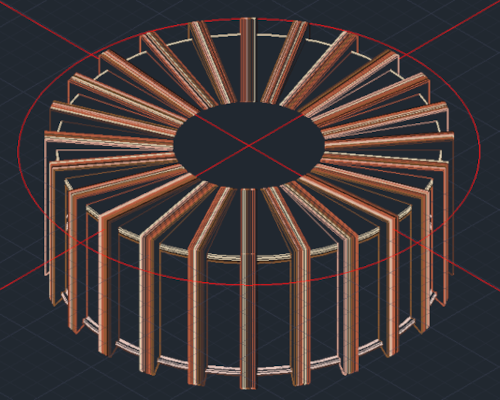
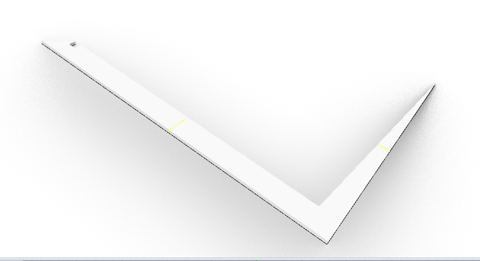
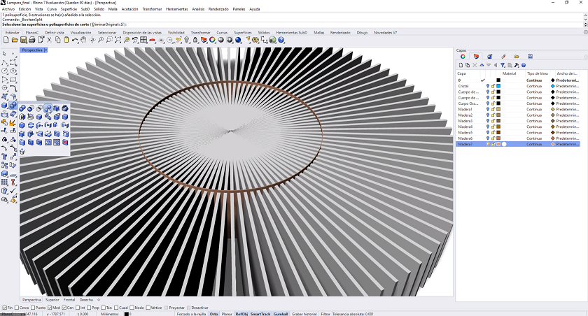
With the Rhino software, the lateral reinforcements of the lamp structure have been modeled. The goal is to compare different CAD manufacturing software to understand which is the best option for the future. Although I liked Rhino a lot, for now I will continue with Autocad.
 Construction of the lateral reinforcements in Rhino
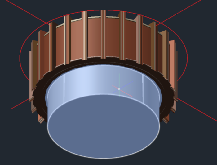
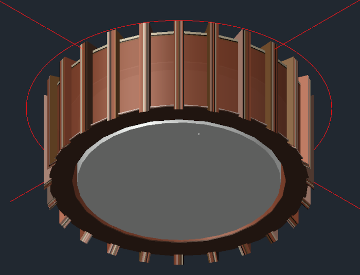
Here I leave some screenshots of the construction of the lateral reinforcements of the lamp
 Side view of the lamp reinforcements
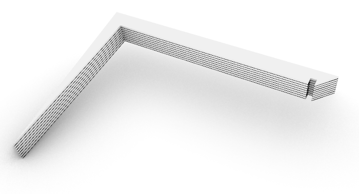 Side view of the lamp reinforcements
AUTOCAD VS RHINOCEROS
I will try to give a brief explanation between the advantages and disadvantages among the most popular CAD software in the world.
ADVANTAGES:
- AUTOCAD
- The tools are easy to use and the learning curve is fairly minimal to be able to draw in 3D.
- The 3D application is very intuitive, unlike gace years they have greatly improved the interface and it is a hoot to see your product instead of imagining what it will look like.
- The speed and accuracy is superior to any other CAD program.
- It's like having a drawing table in front of you.
- RHINO
- The tools are easy to use much like Autocad from which it has been inspired.
- Parametric modeling: Grasshopper allows an easy/fast iterative process
- White Box Render Screen - Looks great as a quick diagram export with no post production required.
- Robust Command Prompts: Rhino was originally created for industrial design and offers many unique modeling commands that put it on par with SolidWorks.
DISADVANTAGES:
- AUTOCAD
- It needs more tools in the 3D, eventually some parametric support.
- Better connection with Revit or Inventor
- Dynamic blocks could get some updates
- Parameters may be more developed;
- The sheet set could evolve further to support a workflow involving data management
- RHINO
- Rhino has very limited sheet layout tools.
- Grasshopper could be better integrated into the main interface.
- The lack of backward compatibility of files can be frustrating.
- In my opinion, the integration between Autocad and 3D max is enormous and difficult to improve..
In my case, it is the advantages of Autocad, they are still superior to the advantages of Rhino. The output files are much cleaner. From Autocad I can use the CNCs directly. Also, at my university Autocad licenses are free, rhino does not have educational licenses and being able to communicate with my work environment is essential.
MY WAY OF WORKING IN AUTOCAD 2D AND 3D
In this section I am going to describe my way of working with Autocad in 2D and 3D. I will be more extensive. I have to confess that I have been working with autocad since 1998 and for me it is always a pleasure to work with him, although nowadays I do not spend much time designing.
My way of proceeding with autocad is very different from normal users for different reasons. I don't usually work with icons but with a text command in the menu.
if you had had to survive as many versions of autocado as I have, you could understand it. Autodesk has been changing the program interface to adapt to less expert users where the visual language is more intuitive.
In 2012 autocad had nothing to do with what it was in its day and thanks to my way of working I didn't have to adapt to the new way. Autodesk was going towards its goal and I was going towards mine, drawing in the shortest possible time.
So that you can continue I am going to describe a simple example and describe some steps that make it more comfortable for me.
I am going to try to replicate the design that I have searched on the internet and you will see some differences that make it more pleasant
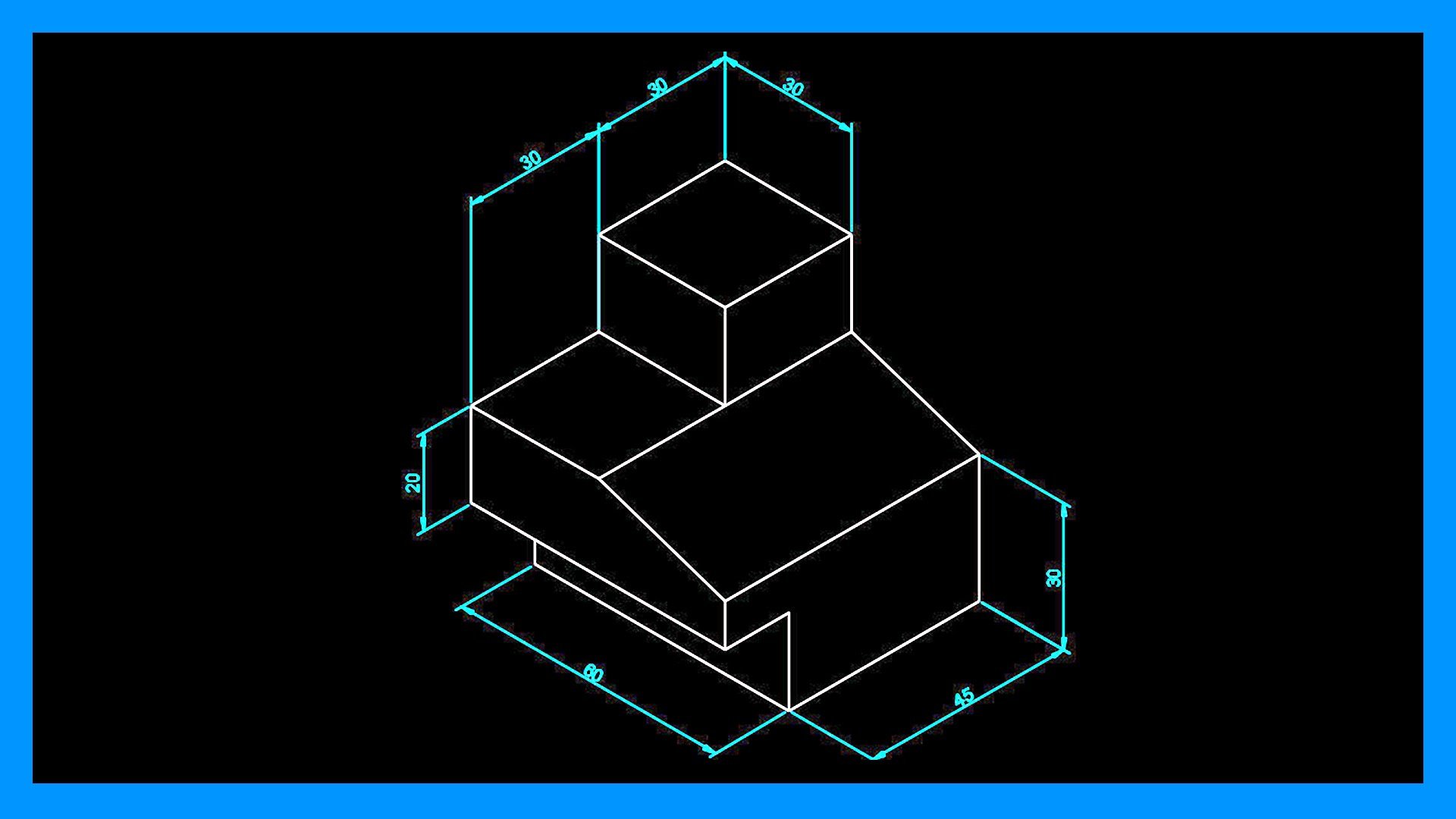
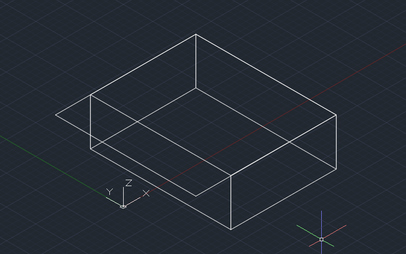
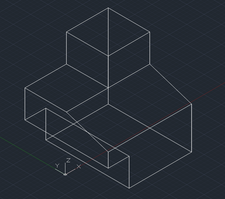
The first step, once we have opened Autocad, is to place the view in 3D to work more comfortably. To do this, we select the lower left corner as marked in the photo
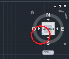
Once clicked, the 3d view will open to work.
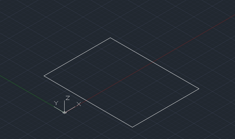
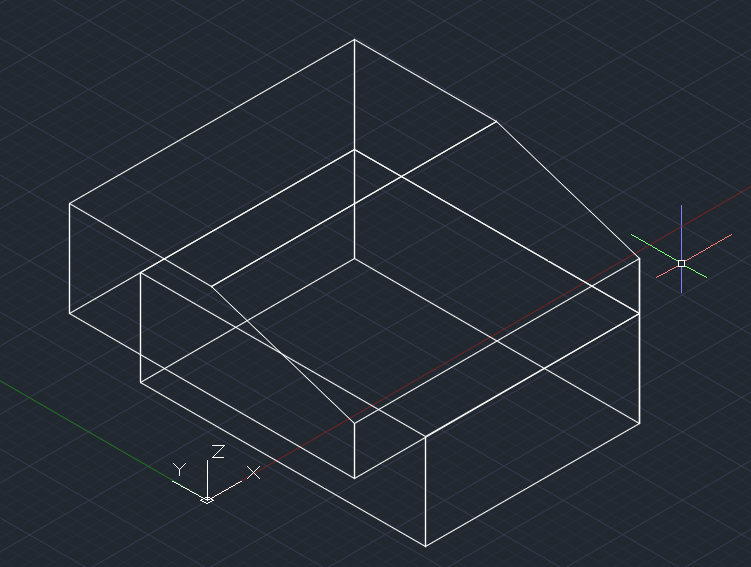
With the _pline command, it will give us the opportunity to draw a polyline. Very important, as you can see, autocad is in Spanish, but since I have gone through all the versions and languages, I work with commands in English. To work with commands in English in an autocad in Spanish we have to put the low line "_" in front of the command
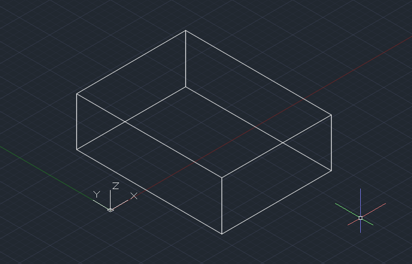
After having made the polyline, we give the extrude command and lift the solid specifying the height.
We start again with the pline command and draw the largest solid
We lift as in the previous step with extrude and apply a cut with the _spline command
Again command _pline and we draw the smallest plan.
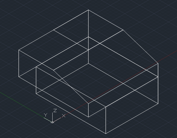
We lift with extrude the last solid in order of height.
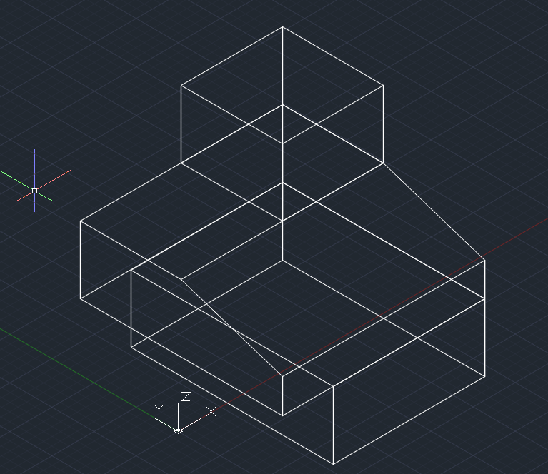
Now we give the union command and we will have a single solid
then we place the origin at the indicated end with the _ucs command, this is fundamental for the dimensions, to have it in height, it is not the same to put dimensions in 2D than in 3D.
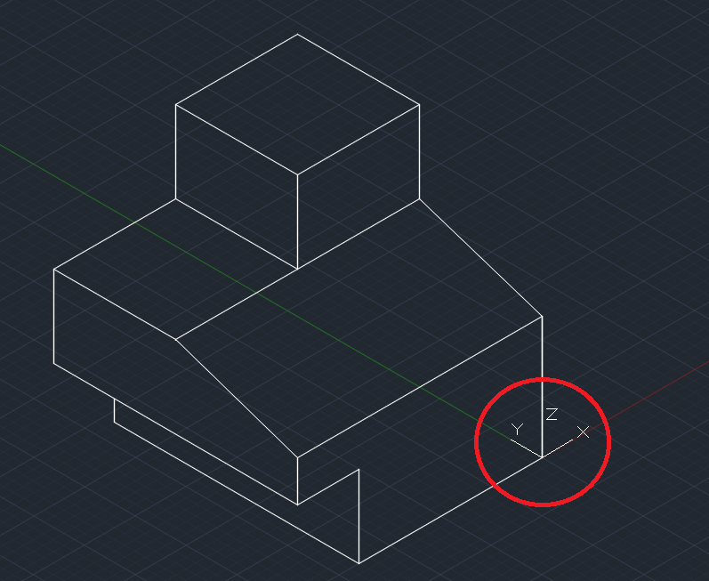
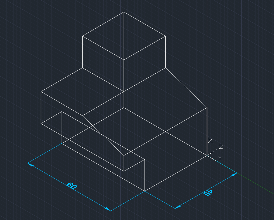
The dimensions are already coming out with the _dim command.
As you can see, I am changing the ucs depending on the type of axis type.
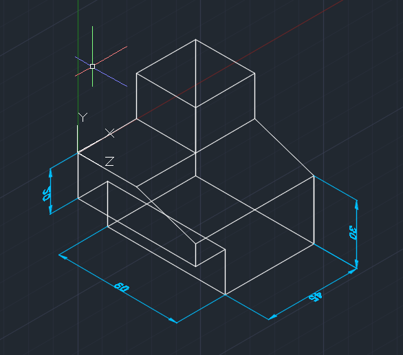
Finally the finished drawing
My drawing is much better than the one I had to represent, my dimensions are in 3d, yours are not. This means that your drawing is in 2D and simulates a 3D. The _ucs command is everything in autocad, once you have understood it you can draw anything or path.
RENDERING
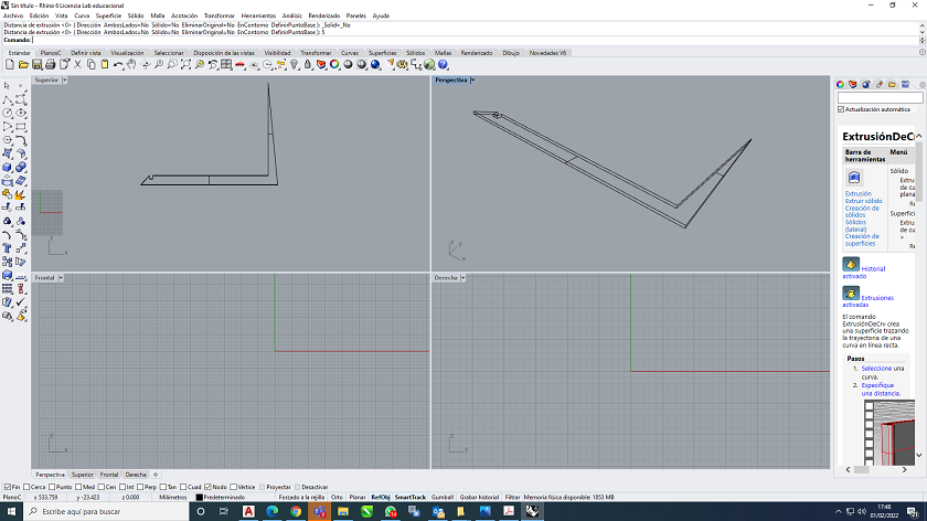
In this section I am going to talk about the process he used to model a three-dimensional object. At first, I tried to explore some of the programs that were included in this week's repository. I was practicing with rhinoceros 6 and as a testimony of this process I leave some screenshots of the modeled object.
 Flexible Wood Modeling in Rhino 6
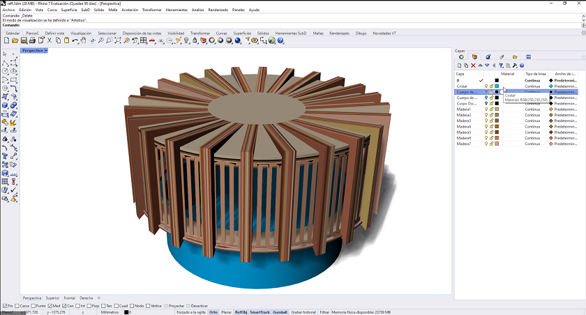 Final modeling in Rhino 6
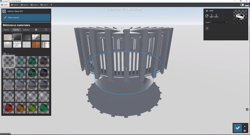 Introduction of 3D modeling in lumion for rendering
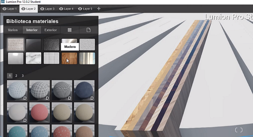 Application of materials in Lumion
After working with rhino 6 and lumion, I decided to try modeling with 3DStudio Max. The choice of this software was due to a couple of reasons. First, I had already worked with it on other occasions and second, it is a very complete software that allows you to model, then render and finally animate the objects.
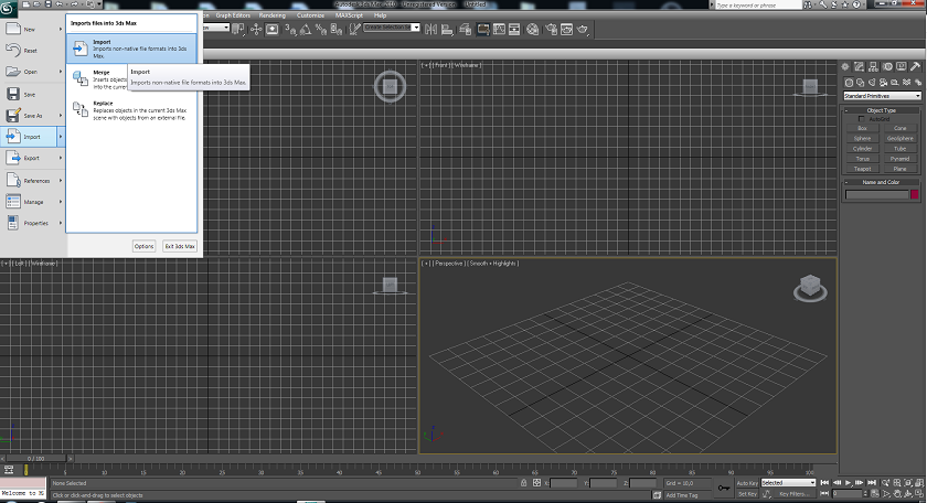 This image shows when modeling is imported into Autocad
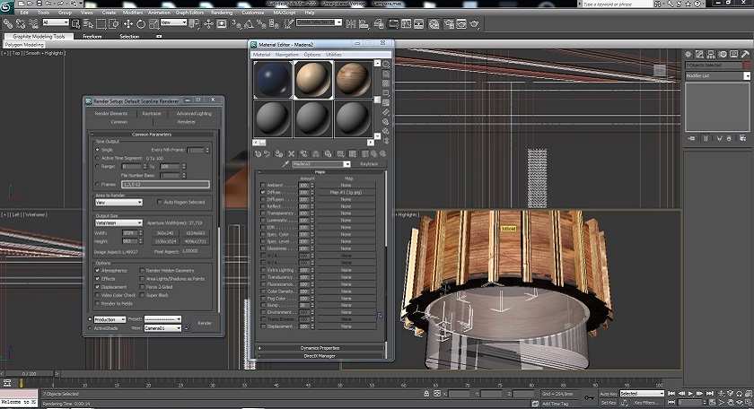
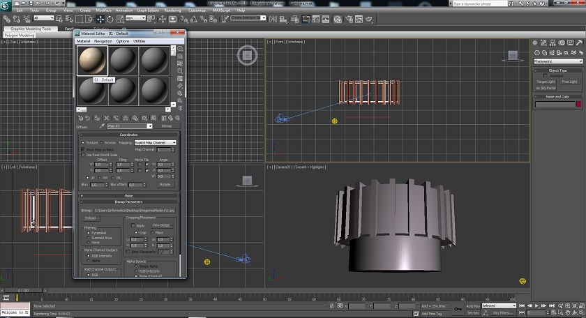 This image shows when the materials are made in 3DStudio
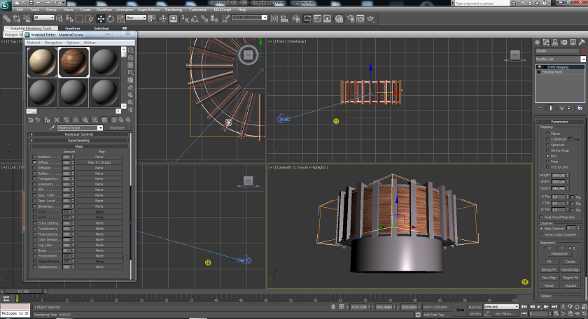 Materials are applied on objects
 Final modeling with all materials applied
Below is the rendered image of the object.
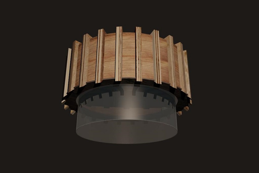 Render of the lamp
ANIMATION
In this section we have proceeded to animate the lamp object. The idea is that all the elements are deposited from top to bottom for assembly and at the end some reinforcing structures close the lamp.
At the end of the video you can see the glass go up and down. This is a move I would like the lamp to make.
MY FILES
Here I am uploading the files that I have been making this week
CONCLUSIONS OF THE WEEK
This week I was able to practice with software that I had never used before. Some things have been very useful to me because they are being used by many designers in the industry and I never had a chance to practice with them.
Knowing that there are softwares like Gimp, and that these are optimal for editing images, has been very useful to me. It has helped me for the composition of my web page. This software not only allows me to reduce the size but also lets me choose which part to use. The effects were very pretty.
Another thing that was very interesting for me was remodeling and rendering with 3D Studio max. I haven't worked with it for many years, but we must admit that the interface is friendly and easy to use. Also, the animation was not difficult at all.
What I liked least is the little time I had available. I really enjoy drawing and learning. Having more time available would be great.


