WEEK 08
ON THIS PAGE WE WILL FIND A BRIEF DESCRIPTION OF MY JOB THROUGHOUT THE EIGHTH WEEK
GENERALITIES
PIC microcontrollers (known simply as PICs) are integrated circuits that can be programmed to execute a sequence of instructions automatically. The program is written on a computer in a suitable programming environment (for example, in the C language) and then transferred as binary code to the microcontroller's program memory for execution at power-up. PIC microcontrollers are manufactured by the Microchip company and basically consist of a CPU, memory spaces for programs and data, and various peripherals for interaction with the outside world.
| Day | Wenesday | Thursday | Friday | Saturday | Sunday | Monday | Tuesday |
|---|---|---|---|---|---|---|---|
| 09:00 | |||||||
| 10:00 | Meeting CT | Assigments | Assigments | Local Review | |||
| 11:00 | Meeting CT | Assigments | Assigments | Local Review | |||
| 12:00 | Assigments | Assigments | |||||
| 13:00 | Assigments | Assigments | Regional Review | ||||
| 14:00 | Assigments | Assigments | Regional Review | ||||
| 15:00 | Fabacademy | Practice | write Documents | ||||
| 16:00 | Fabacademy | Practice | write Documents | Review Documents | |||
| 17:00 | Fabacademy | Practice | Assigments | write Documents | Review Documents | ||
| 18:00 | Fabacademy | Practice | Assigments | write Documents | Review Documents | ||
| 19:00 | Practice | Assigments | write Documents | Review Documents | |||
| 20:00 | |||||||
| 21:00 | Tutorial | Tutorial | Assigments | write Documents | |||
| 22:00 | Tutorial | Tutorial | Assigments | write Documents | Write Documents | ||
| 23:00 | Tutorial | Tutorial | write Documents | Write Documents | |||
| 24:00 | Tutorial | Tutorial | write Documents | ||||
| 01:00 | |||||||
| 02:00 |
In this practice the objective is to start programming electronic boards built by myself. There are several things to learn at the same time.
Learn to read a spreadsheet
Attach the microcontroller (ATTINY44-SSU). Click Here for more information about Datasheet
MAIN FEATURES:
- High performance, low power AVR® 8-bit microcontroller.
- 4K byte of in-system programmable program memory flash.
- 256 bytes in-system programmable EEPROM.
- I/O and packages (14-pin SOIC, 20-pin QFN/MLF: Twelve programmable I/O lines).
- Operating voltage: ( 2.7 - 5.5V ).
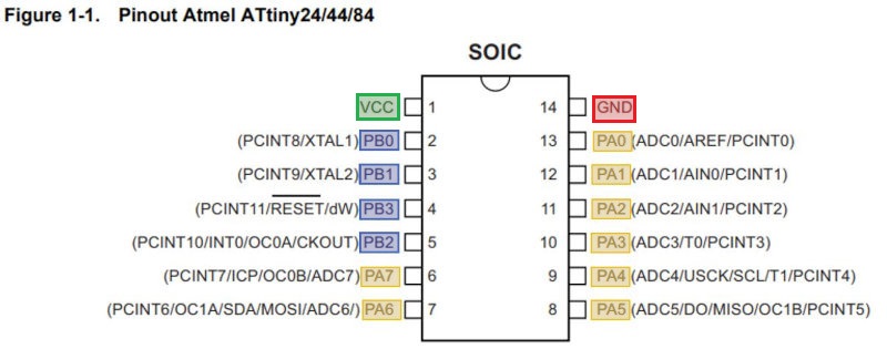
PIN CONFIGURATIONS:
- There are (Vcc and Gnd).
- PB pins (0-3).
- PBA pins (0-7).
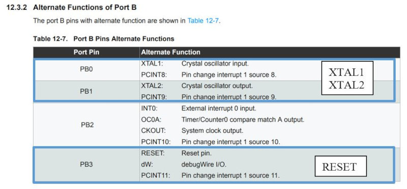
- Pin PB3 is RESET.
From the data sheet of the Atmel® ATtiny24/44/84 we can learn a series of features that will not be very useful when designing and programming the ATtiny 44. This microprocessor is a low-power 8-bit CMOS based on the architecture AVR Enhanced RISC. So fast that it is capable of executing powerful instructions in a single clock cycle, the Atmel ATtiny24/44/84 yields close to 1MIPS per MHz, allowing the system designer to optimize power consumption versus processing speed. .
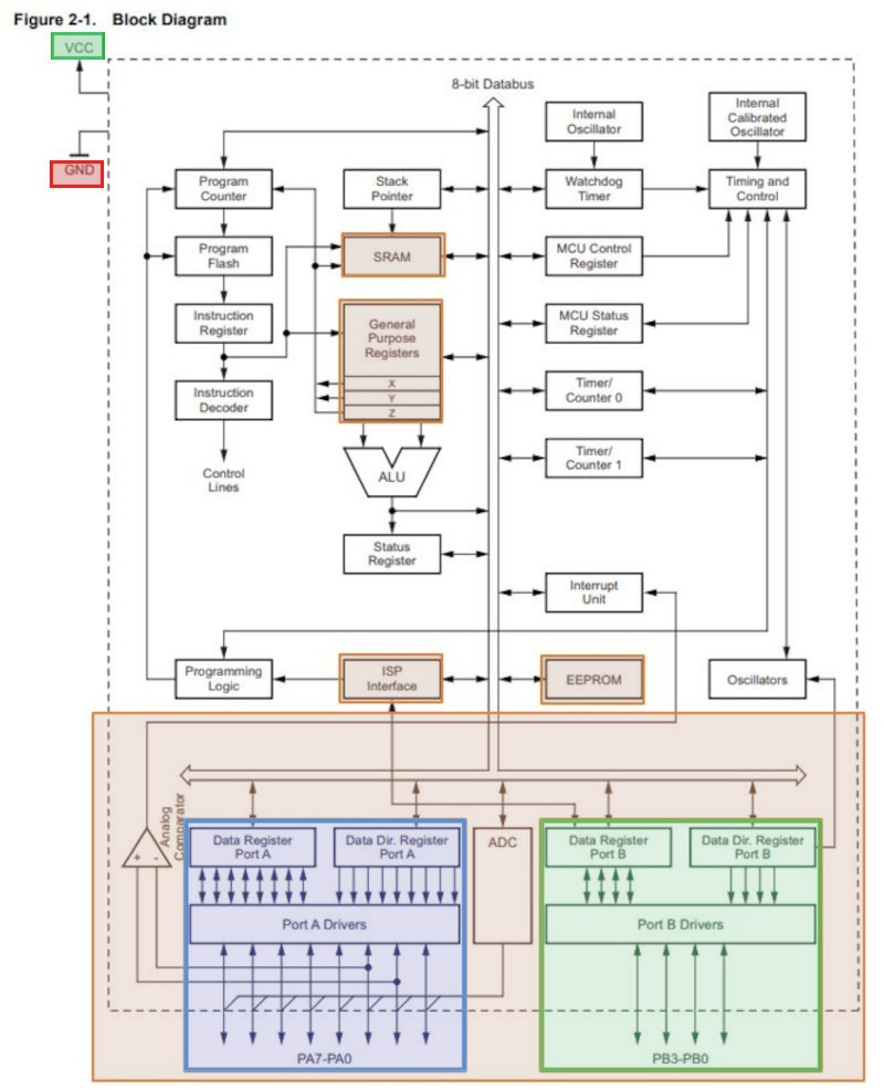
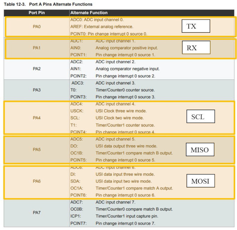
In the diagram (which we can find in the data sheet), the digital ports are differentiated from the analog ones (PA), this is very important since the input and output sensors are manufactured to be coupled in precise output typologies. The PA port (0-7) appears in blue and the PB port (0-3) is green, it is also important to identify the VCC (Supply Voltage) and GND (Ground), the SRAM and EEPRON memories, the 32 registers ( general purpose register) connected to the arithmetic logic unit (ALU) and the ISP interface.
On page 3 of the data sheet appears the description of the ports, which we will reflect to complete the work.
Port B (PB3...PB0) Port B is a 4-bit bi-directional I/O port with internal pull-up resistors (selected for each bit). The Port B output buffers have symmetrical drive characteristics with both high sink and source capability except PB3, which has the RESET capability. To use pin PB3 as an I/O pin instead of RESET pin, program (‘0’) RSTDISBL fuse. As inputs, Port B pins that are externally pulled low will source current if the pull-up resistors are activated. The Port B pins are tri-stated when a reset condition becomes active, even if the clock is not running.
Port A (PA7...PA0) Port A is a 8-bit bi-directional I/O port with internal pull-up resistors (selected for each bit). The port A output buffers have symmetrical drive characteristics with both high sink and source capability. As inputs, Port A pins that are externally pulled low will source current if the pull-up resistors are activated. The port A pins are tri-stated when a reset condition becomes active, even if the clock is not running.
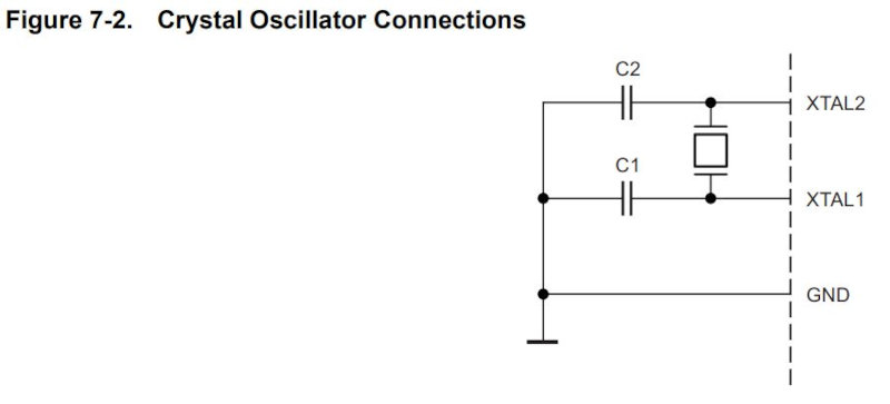
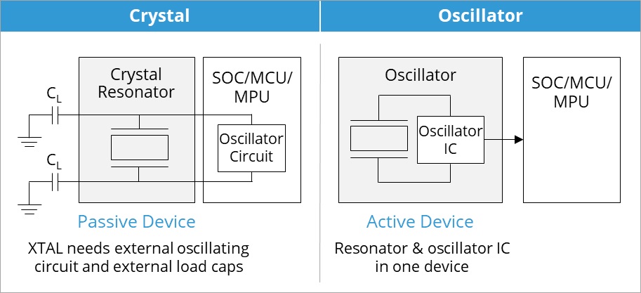
CRYSTAL OSCILLATOR: XTAL1 and XTAL2 are input and output, respectively, of an inverting amplifier which can be configured for use as an on-chip oscillator, as shown in Figure 7-2 Either a quartz crystal or a ceramic resonator may be used. The optimal value of the capacitors depends on the crystal in use, the amount of stray capacitance, and the electromagnetic noise of the environment.
if we don't want to use the internal clock but an external clock, as we do with our ATTiny board, page 25 describes how to connect an external clock and what kind of external clocks you can use. When choosing an external clock, you must set the CKSEL fuses to 0000.
On my Atiny44 board I used a resonator as shown in picture 8 resonator connection.
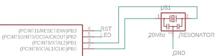
One of the differences between crystal and resonator is that a resonator has build in capacitors. As I understand it, an oscillator is built from a crystal and two capacitors. See this pic and focus on the electronics symbol: resonator has crystal symbol and on both legs capacitors:
the communication pins: MISO pin 5 and MOSI pin 6, which we use to program our ATTiny using our USBTiny
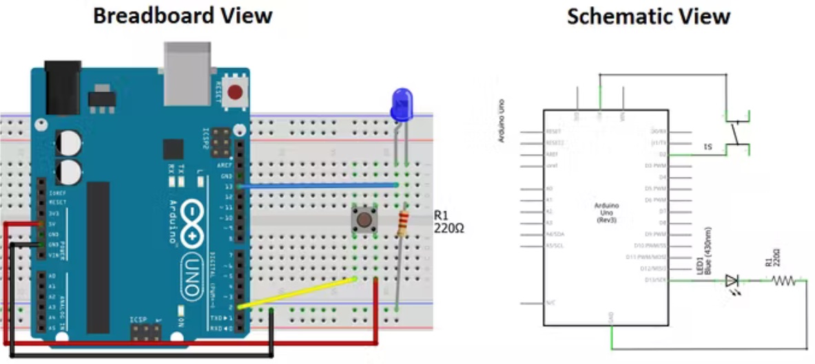
PROGRAMMING POWER LED WITH THE BUTTON
In this practice, a code has been developed so that the electronic board made with Attiny 44 will start blinking when the button is pressed and as soon as the code has been entered.
I have used the C programming language and done it with Arduino ID. Although the Arduino electronic boards are an adapted circuit, the software is open source and can be installed on different microcontrollers.
Support information by clicking Here.
Searching the Internet there are a lot of tutorials on microcontroller programming. For example, I have seen these to learn about programming with Arduino.
Here I leave the address to search for the files I have seen by clicking Here.
There are a lot of examples and many have helped me in compiling the code. The first 3 are fundamental but the one that most resembles my case is Tutorial 3. I leave the link here.
For more information by clicking Here.
It explains very well that digital inputs and outputs will be used.
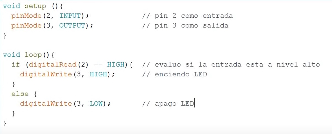
Now, we are going to use two functions Void Setup and Void Loop.
Void Setup is the first function to be executed in the program and is used to configure, initialize variables, start using libraries, etc… ... This function is the core of all Arduino programs and is used for active control of the license plate. The loop function is executed right after setup.
In the tutorial I learn to write my first on and off program
After I have written the program, I only have to verify it by clicking on the "v" button.
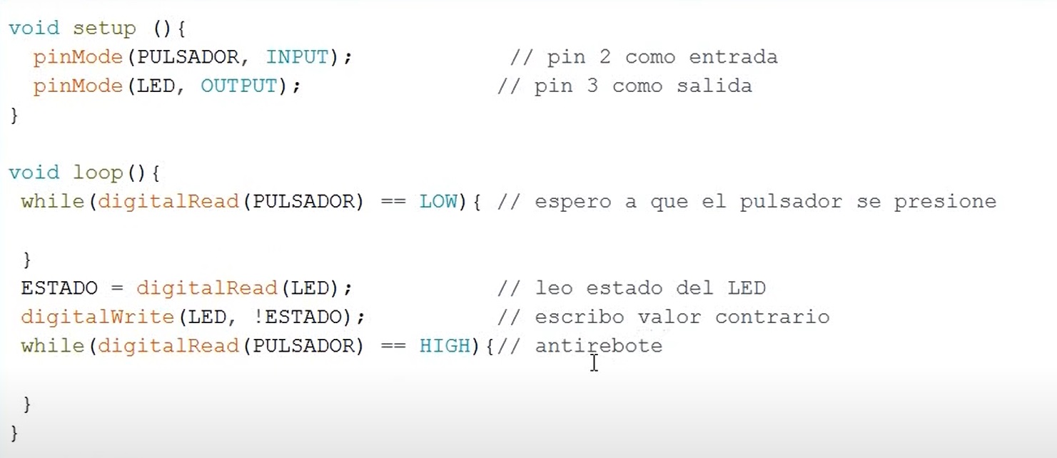
Now, after learning how to program with the power on and power off, I'm going to create a new program to use the button differently.
In this case, if I press the button, the LED turns on and if I press it another time, it turns off. Let's see how to do it.
Now, I install the arduino software from this link.
If you want to download the software, you can do it from this link.click Here.
In my case I will use another processor board, so I will have to check the software.
If you want to download the libraries, you can do it from this link.click Here.
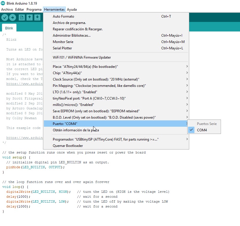
SOFTWARE PROGRAMMING
For the programming of the board, I have used Arduino. Before using it you have to make some changes in the software.
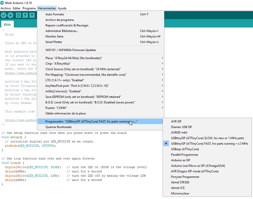
 Uploading microchip firmware to Arduino
The first thing to add are the processor components. The Arduino is an open source program but intended for Arduino boards. To be able to use it with our cards, you have to add the components.
nother preliminary step is to find out if the microprocessor pins and the circuit outputs match.
Checking the microprocessor pins
In our case, it is like this. We will not have any problem in programming.
 Verification of the installed microchip
We check, whether it recognizes the port where the programmer is connected.
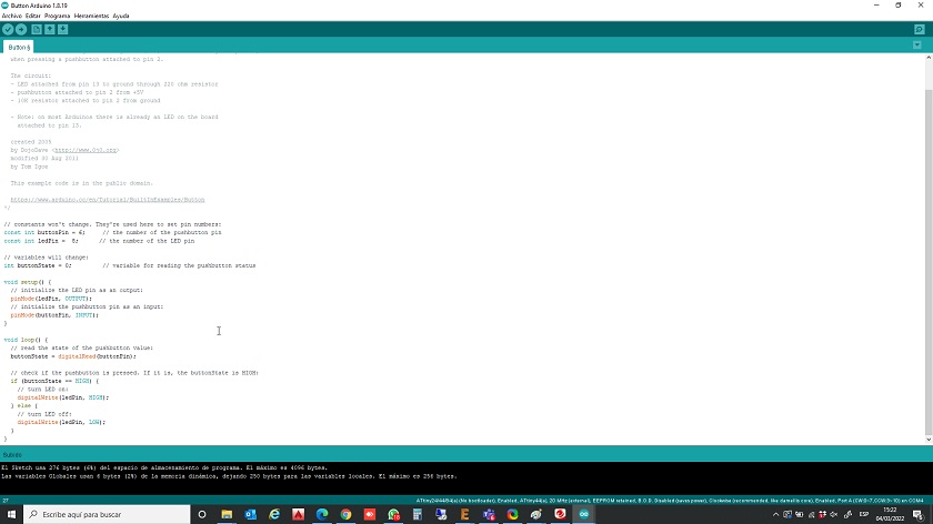 Uploading the "Button" program to the board
We verify that the programmer is the right one.
From the basic examples system we load the program for the button and burn it into the fabricated board.
Everything works properly.
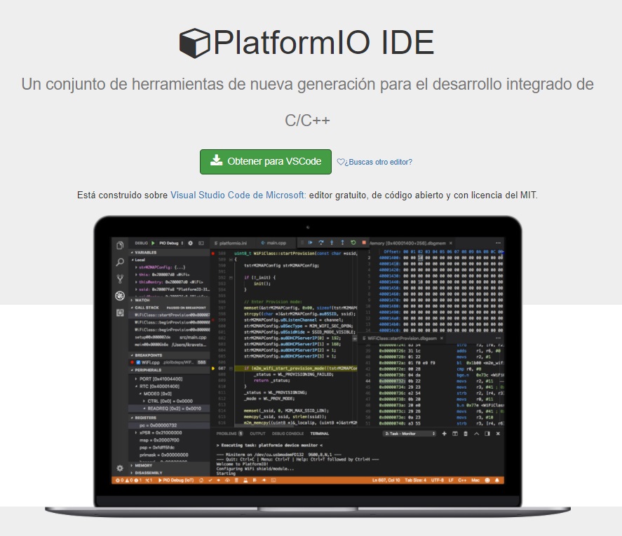
PROGRAMMING WITH PLATFORMIO
Install the Visual Studio Code.
If you want to download the software, you can do it from this link.click Here.

Install PlatformIO: This software can, once installed, be integrated into Visual Studio, software that I already use to work with Html. It is very comfortable because, like Arduino, it has other electronic cards (microcontrollers) pre-installed.
If you want to download the software, you can do it from this link.click Here.
Then, we will follow the steps described by the developers.
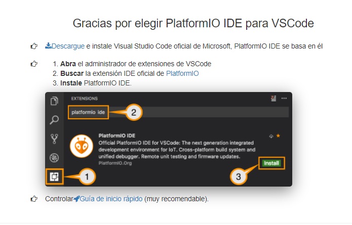
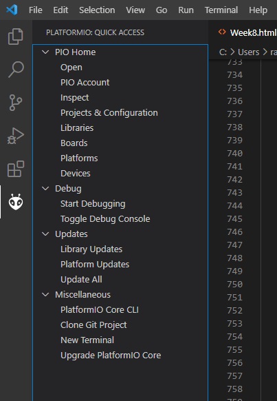
We look for the plugin in the Visual Studio interface as in the image here.
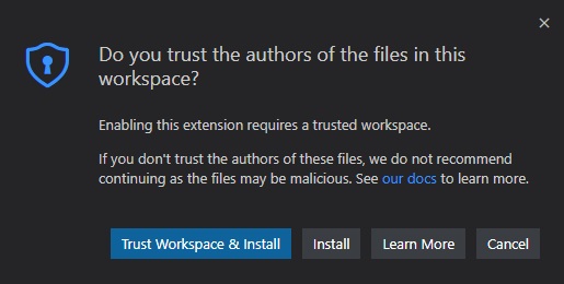
The first message asks us for trust in the developers
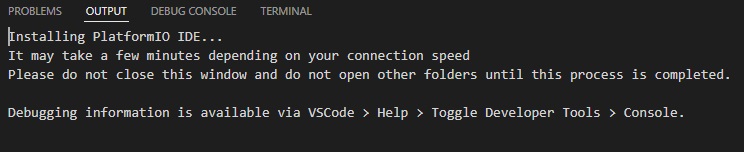
The second message tells us that it will take a little while and we have to wait.
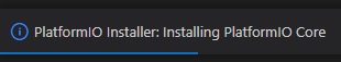
At the bottom right we also have information about the installation process.
Luckily I don't have any errors, so I'm going to reboot and see if there are any changes.
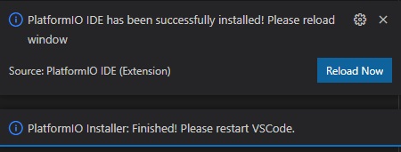
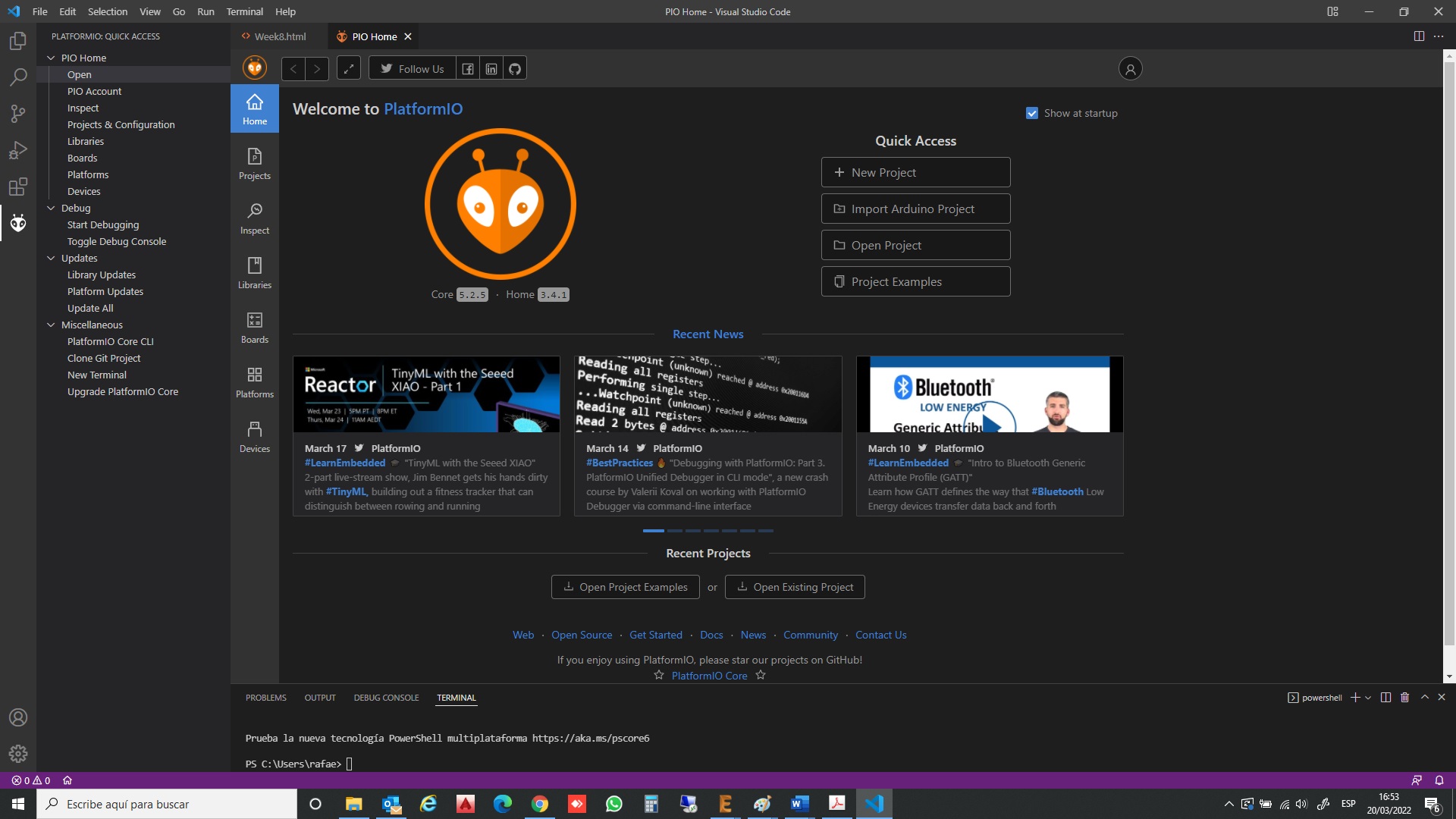
In fact, the plugin appears.
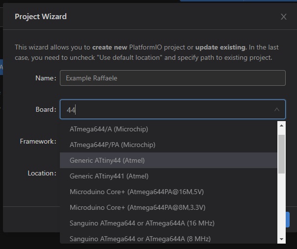
Once I open the plugin I have a number of options, I'll start by creating project.
Created a new project as in the image
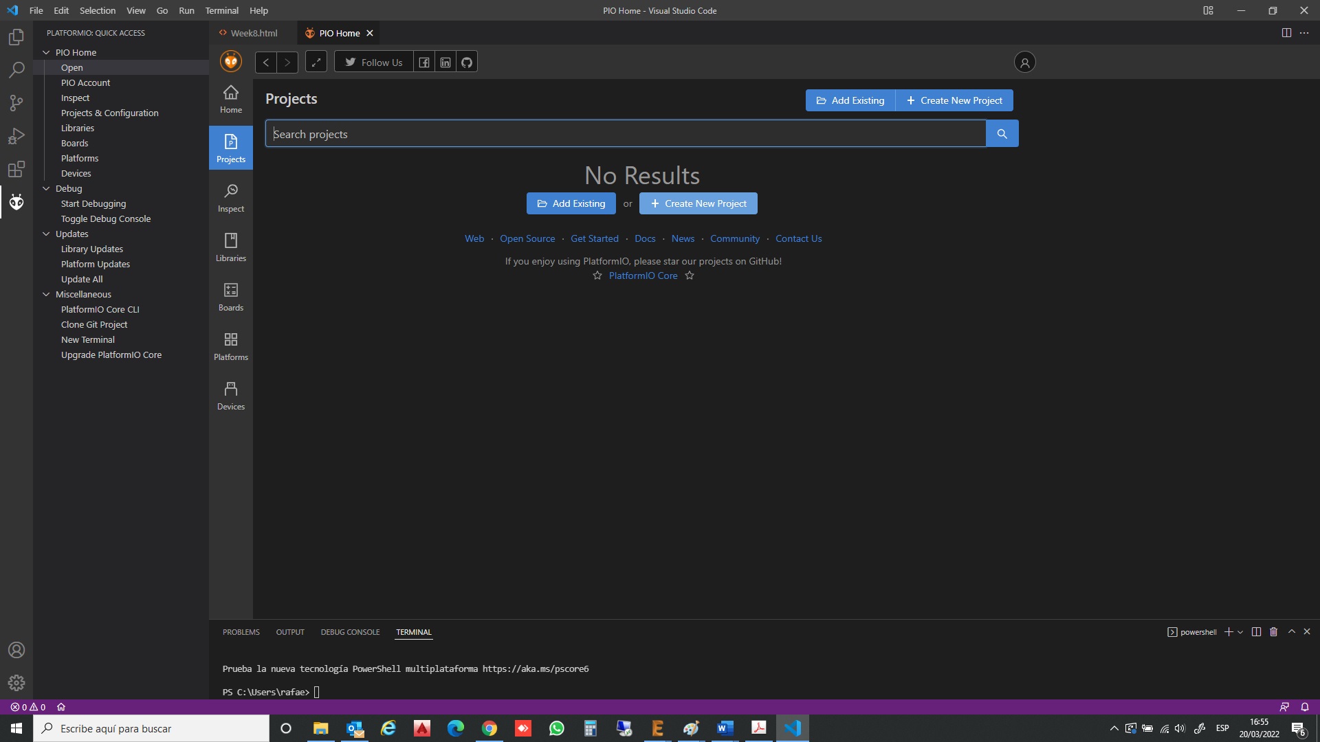
I choose my option, and to work.
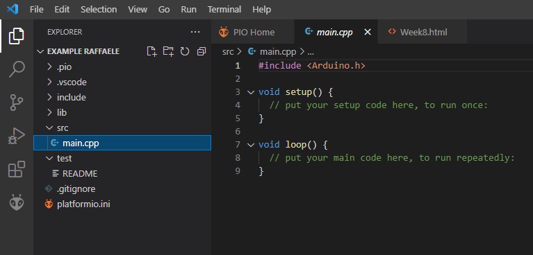
In the source tab, src, there is the main file, to work with the code:
With PlatformIO, all system libraries can be accessed, which with ArduinoID cannot, because they are hidden (or protected). To compile the pr
To compile the programming, it is done by activating the build tool, in the lower left part of the environment window.
All you have to do is write the code and start working
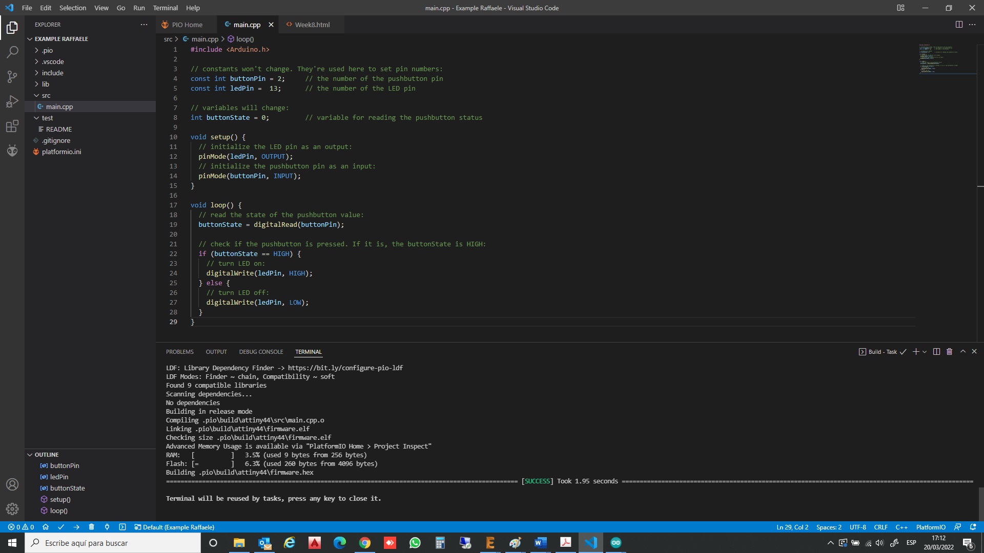
It's ready to work
CONCLUSIONS OF THE WEEK
It has been one more step to learn about the manufacture of electronic boards and their programming. It is getting more and more complicated but I always like to learn.
I was searching the internet for other programming programs. There is a lot of material on the net and very well explained. I have been comfortable working with Arduino and PlatformIO. VisualCode is a great program.
“What went wrong”: The milled plate. But I really enjoyed trying to fix it. I think that in the solution there are many connections between a good maker and a designer.
It is a week where you can learn many things about programming. Preparing the documentation wastes a lot of time and it's a shame.
“What Went Right”: Eagle software is also made for newbies. It helps a lot.
“What will you do differently next time?”: It would be interesting to add some time to assimilate about programming.
MY FILES
Here I am uploading the files that I have been making this week


