WEEK 14
ON THIS PAGE WE WILL FIND A BRIEF DESCRIPTION OF MY JOB THROUGHOUT THE WEEK FOURTEENTH
GENERALITIES
This week in Spain spring has exploded, after a strange month of April. This week I am going to investigate more about the possibilities of the ESP32 microcontroller. As it has a bluetooth and wifi module, I am going to try to connect the coon mobile with the plate to turn on the leds.
In the lamp that I want to build I would like to add a control on and off with the mobile, so everything will go in the right direction. As I have never worked with these things, everything is going to be very new and I don't know if I will achieve the objective, we hope everything goes well!!!!
I will try to provide in my documentation all kinds of details to make my knowledge. We hope well!!!
| Day | Wenesday | Thursday | Friday | Saturday | Sunday | Monday | Tuesday |
|---|---|---|---|---|---|---|---|
| 09:00 | |||||||
| 10:00 | Meeting CT | Assigments | Local Review | ||||
| 11:00 | Meeting CT | Assigments | Local Review | ||||
| 12:00 | Assigments | ||||||
| 13:00 | Assigments | Regional Review | |||||
| 14:00 | Assigments | Regional Review | |||||
| 15:00 | Fabacademy | Practice | Assigments | ||||
| 16:00 | Fabacademy | Practice | Assigments | Review Documents | |||
| 17:00 | Fabacademy | Practice | Assigments | Assigments | Assigments | write Documents | Review Documents |
| 18:00 | Fabacademy | Practice | Assigments | Assigments | Assigments | write Documents | Review Documents |
| 19:00 | Practice | Assigments | Assigments | Assigments | write Documents | Review Documents | |
| 20:00 | |||||||
| 21:00 | Tutorial | Assigments | Assigments | Assigments | write Documents | ||
| 22:00 | Tutorial | Assigments | Assigments | Assigments | write Documents | Write Documents | |
| 23:00 | Tutorial | Tutorial | write Documents | Write Documents | |||
| 24:00 | Tutorial | Tutorial | write Documents | ||||
| 01:00 | |||||||
| 02:00 |
Another complicated week. Although the topics to be studied are very fun, there is a lot of work with programming languages. On the one hand it is fun but you have to investigate a lot. Documentation on the internet is very bad and the codes they leave behind are false realities. None of them works. On the one hand, because they work with Arduino boards and the ESP32, you have some specific languages that are specific to this microprocessor. After hours and hours of trial and error you realize that they can't work. To give an example, in the Arduino codes they talk about turning on an analog pin, but they use a digital GPIO. The ESP 32 Bluetooth library does not support this expression. It has taken me many hours to discover how to adapt a code to my board and what I wanted to achieve. Well in the end I got 80% of what I wanted to discover. On the one hand I am satisfied because I have achieved it alone. Today, Sunday, I am writing and I hope to resolve the issue of the power of the LED light before Wednesday!
PREPARING THE SMARTPHONE APP
I am going to try to use the application "MIT APP INVENTOR" to draw an application that is able to turn on and off two leds and can reduce and increase the intensity.
To start I will have to give the entry "Create Apps"
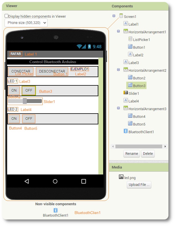
After having created screen one with the buttons that I am going to use, I go to the part where a command or function is associated with the buttons.
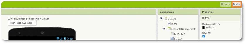
It is in this part where the application is programmed
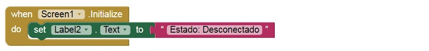
Upon opening the application, we will give information about the connection status that will probably be offline.
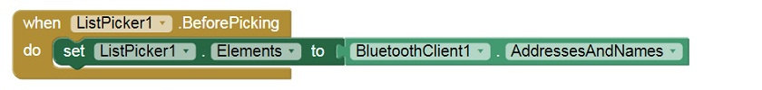
With this function, when I click on the button, a list appears where it informs me of all the available Wi-Fi before choosing. At this point I choose and establish the connection between the list possibilities in the address and the names of the bluetooth client that there are.
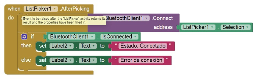
Once I have clicked to establish the connection, two things can happen:
First option, If bluetooth is connected, then a message will appear: Connected status.
otherwise, I will get a message: in connection error
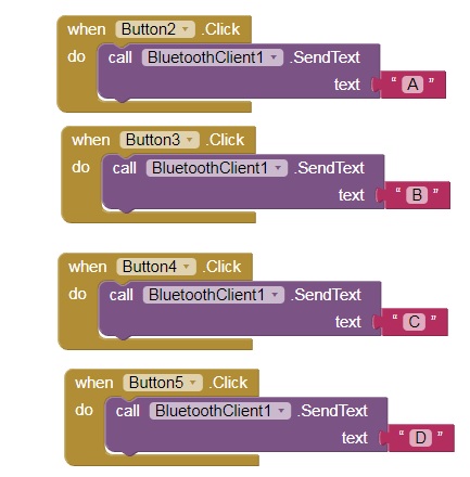
Now, I'm going to give you the button commands. First of all I am going to perform the functions of LED1. Button 2, which is "ON", will send a Message A. The Microprocessor is ready at the moment it receives message "A" it will turn on and pressing the Button "OFF" will send a message "B". When we receive the "B" we will establish the Off. The same goes for the buttons of the "LED2" Button.
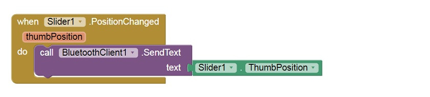
Finally we are going to program the brightness level. To be able to establish a programming of the LED1 light, it is only necessary to give the information to the microprocessor about the position. We have established 9 positions and each of them corresponds to a level of intensity.
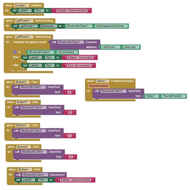
Well, finally I am going to leave the entire function code so that you can see it.
Once I have finished preparing the application, you just have to transfer it to the mobile!
To achieve this, I'm going to click on the button on the web page.
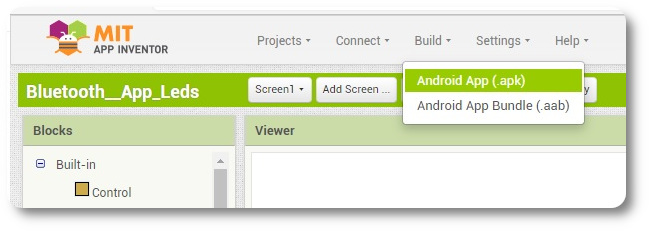
Pulse Android App (.apk)
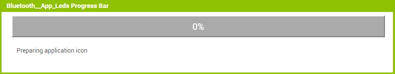
I'm going to make myself a coffee while I prepare the application!!
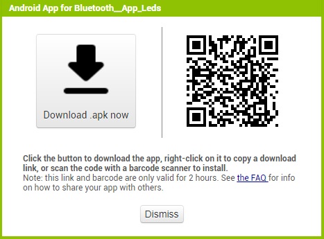
Linked the Qr Code to the mobile, the application is downloaded. First step finished, we must continue with the programming!!
IT'S TIME TO WORK WITH ARDUINO IDE!!!
After having studied the documentation on the internet, you can compile the code in Arduino that managed to work the LEDs!
- #include "BluetoothSerial.h"
- #if !defined(CONFIG_BT_ENABLED) || !defined(CONFIG_BLUEDROID_ENABLED)
- #error Bluetooth is not enabled! Please run `make menuconfig` to and enable it
- #endif
- #define RedLed 15
- #define GreenLed 14
- String recv = "";
- BluetoothSerial SerialBT;
- void setup() {
- Serial.begin(115200);
- pinMode(RedLed, OUTPUT);
- pinMode(GreenLed, OUTPUT);
- ESP32_LED_Control");
- Serial.println("The device started, now you can pair it with bluetooth!");
- Serial.println("The device started, now you can pair it with bluetooth!");
- }
- void loop() {
- while (SerialBT.available())
- {
- char string = SerialBT.read();
- recv = recv + string;
- delay(1);
- }
- if (recv == "A")
- {
- digitalWrite(RedLed, HIGH);
- }
- if (recv == "B")
- {
- digitalWrite(RedLed, LOW);
- }
- if (recv == "C")
- {
- digitalWrite(RedLed, HIGH);
- }
- if (recv == "D")
- {
- digitalWrite(RedLed, LOW);
- }
- recv = "";
- }
Well, I'm going to post a video to demonstrate that everything works and to complete the weekly task, I'm going to use the es32 as a wifi module.
I am going to continue investigating, I would like to be able to learn how to change the intensity of the led light!!!
Making a digital potentiometer
In this section I have been working to make an intensity regulator. I'll be using it for my final lamp, so I'll have to do a lot of research.
After doing a lot of research, I tried more than five different codes and none of them worked for me.
The code that was closest to my intensity regulator, gave me the problem that when I zeroed the slider, the LED turned off and when it continued to increase it turned on without any regulation.
In the end I told my instructor Alvaro Macia that when studying the code he replaced Digitalwrite with PinCwrite. He worked the first time and explained to me that the digitalwrite statement for ESP32 doesn't work. I'm going to put the code and the demo video.
- #include "BluetoothSerial.h"
- #if !defined(CONFIG_BT_ENABLED) || !defined(CONFIG_BLUEDROID_ENABLED)
- #error Bluetooth is not enabled! Please run `make menuconfig` to and enable it
- #endif
- int salida = 15;
- //Variables de control y/o lectura
- char valor;
- String readString;
- BluetoothSerial SerialBT;
- // setting PWM properties
- const int freq = 5000;
- const int ledChannel = 0;
- const int resolution = 8;
- void setup() {
- // configure LED PWM functionalitites
- ledcSetup(ledChannel, freq, resolution);
- // attach the channel to the GPIO to be controlled
- ledcAttachPin(salida, ledChannel);
- pinMode(salida, OUTPUT);
- Serial.begin(9600);
- SerialBT.begin("RAFAB"); //Bluetooth device name;
- Serial.println("The device started, now you can pair it with bluetooth!");
- }
- void loop() {
- char dato =SerialBT.read();
- switch(dato) {
- case 'A' :intensidad();
- break;
- }
- }
- digitalWrite(RedLed, LOW);
- }
- void intensidad(){
- delay(15);
- while (SerialBT.available()){
- char C = SerialBT.read();
- readString += C;
- }
- if (readString.length()>0){
- ledcWrite(ledChannel,(readString.toInt()));
- readString = "";
- }
- }
Now I'm going to put the video demo
YOU HAVE TO TRY IT WITH THE WIFI, TO SEE IF I GET IT!!!!
Now to complete the weekly task I am going to try to use the es32 as a wifi module.
The steps to follow are the following:
- Connect the Button on the GPIO 15.
- Compile the program on Arduino.
- Run the program on the PCB
- Open the monitor and see the established connections
- In the window the page where the on and off button is placed will be declared
- Turn on and off via Wi-Fi.
I'm going to put the programming language via wifi, you can copy and paste like the others!!!!
- #include <WiFi.h>
- #define LED 15
- String p="off";
- const char *ssid = "Cerveza";
- const char *password = "barata";
- WiFiServer server(80);
- void setup() {
- pinMode(LED, OUTPUT);
- digitalWrite(LED, LOW);
- Serial.begin(115200);
- Serial.println();
- Serial.println("Configurando");
- WiFi.begin(ssid, password);
- Serial.print("Conectandome");
- while (WiFi.status() != WL_CONNECTED)
- {
- delay(500);
- Serial.print(".");
- }
- if (LEDstate==true){
- digitalWrite(LED,LOW);
- delay(200);
- }
- else digitalWrite(LED, HIGH);
- }
- Serial.println();
- Serial.print("Conectado, La dirección IP es: ");
- Serial.println(WiFi.localIP());
- server.begin();
- Serial.println("Servidor iniciado");
- }
- void loop() {
- WiFiClient client = server.available();
- if (client) {
- Serial.println("Nuevo cliente.");
- String currentLine = "";
- while (client.connected()) {
- if (client.available()) {
- char c = client.read();
- Serial.write(c);
- if (c == '\n') {
- if (currentLine.length() == 0) {
- client.println("HTTP/1.1 200 OK");
- client.println("Content-type:text/html");
- client.println("Connection: close");
- client.println();
- client.println(" <!DOCTYPE html><html>");
- client.println("<head><meta name=\"viewport\" content=\"width=device-width, initial-scale=1\">");
- client.println("<link rel=\"icon\" href=\"data:,\">");
- client.println("<style>html{font-family: Helvetica; display: inline-block; margin: 0px auto; text-align: center;}");
- client.println(".button {border: none;color: white;padding: 15px 32px; text-align: center;");
- client.println("text-decoration: none;display: inline-block;font-size: 16px; margin: 4px 2px;cursor: pointer;}");
- client.println(".button1 {background-color: #4CAF50;} /* Green */");
- client.println(".button2 {background-color: #008CBA;} /* Blue */");
- client.println("</style></head>");
- client.print("<body><h1>WebServer con ESP32</h1>");
- if(p=="off"){
- client.println("<button type='button' class='button button1' onClick=location.href='/LED=ON'> ENCENDER </button><br><br>");
- }
- else{
- client.println("<button type='button' class='button button2' onClick=location.href='/LED=OFF'> APAGAR </button><br><br>");
- }
- client.print("