WEEK 18
ON THIS PAGE WE WILL FIND A BRIEF DESCRIPTION OF MY WORK THROUGHOUT THE EIGHTEENTH WEEK
GENERALITIES
This section, I understand that it must be a developed container of my final project. Like any project, it has starting conditions, to these starting conditions that summarize the object of the project, we must add a development throughout the academy. Not everything has been manufactured today, everything comes from multiple attempts made over the weeks that we have lived with anxiety and trepidation.
I am sure that my instructors will understand me when I say that the fablab is not only a place to learn and work, it is a living space where a strong capacity for survival and adaptation to abnormal circumstances is acquired. What do I want to say with that? I want to say that not everything is resolved, much remains to be resolved and many of us contribute a grain of sand to this immense beach. Because a beach, because it reminds me since we were little that we used to build castles with sticks, stones, water, sand and a lot of fantasy. The final product was nothing like what we had imagined, but the satisfaction lasted until the day we had the opportunity to start over.

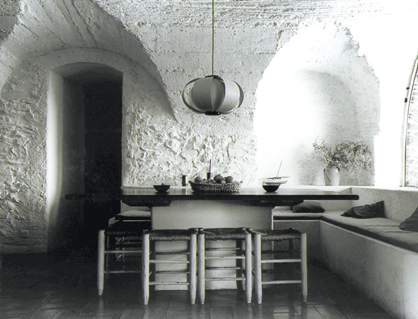
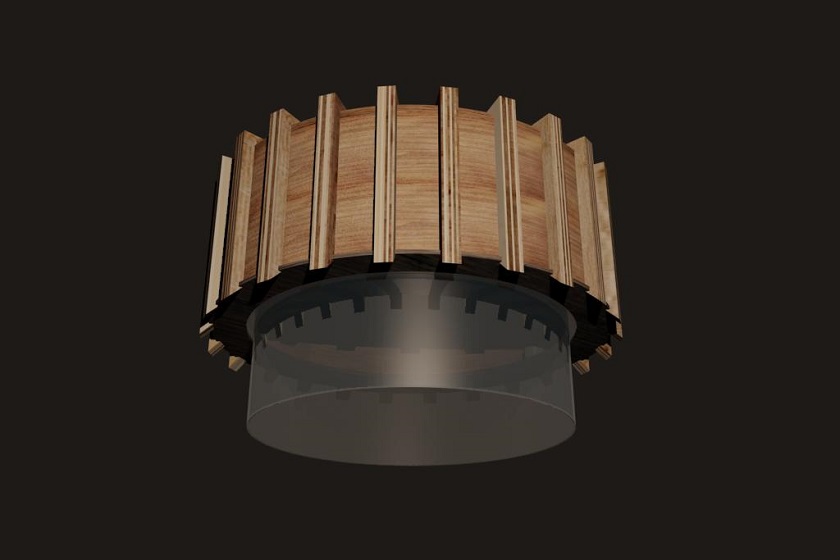
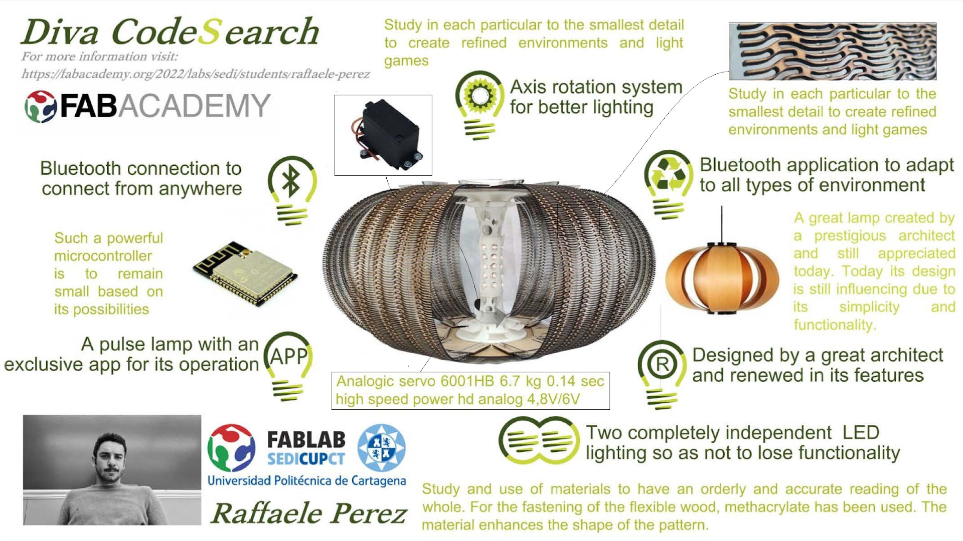
My final project is to make a lamp. But in reality it is not the main object, the main object is to understand how my project can help dozens of students who, throughout the academic year, go through the architecture workshop. Having chosen the lamp designed by another architect is a message that on the one hand wants to celebrate the design of a great architect like Coderch, and on the other push the student to understand the project and contribute his ideas.
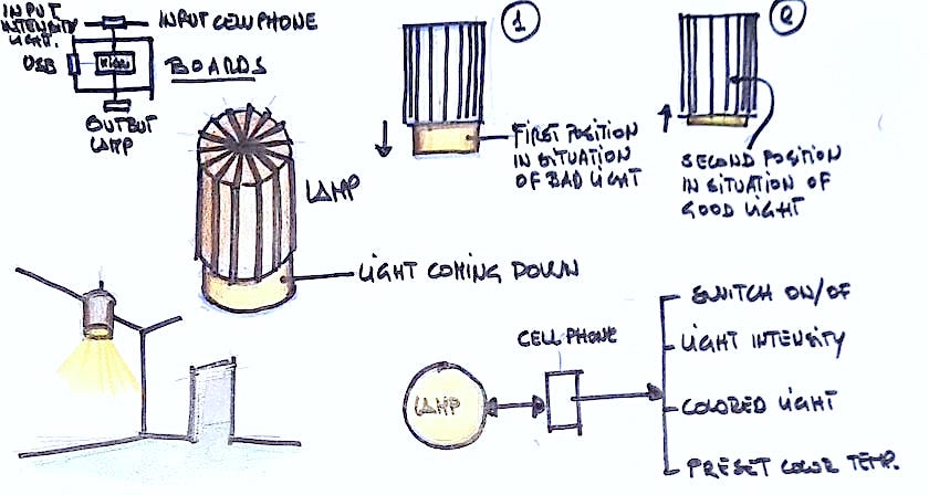
In this lamp I have tried to find functionalities that will transform it into something adaptable to many environments. A bluethoot entry gives me the opportunity to communicate with it to make it adapt to different situations, a profound dilemma for architects. The operation is simple; It has a bluetooth input so that the intensity can be set from the smartphone and the segments that make it up can adopt a posture to reveal its bright interior and provide light to the most demanding environments.
The care of the design has been unique, the characterization of the materials studied in the past weeks has taught me to speed up designs so that I can solve the coupling of materials without the need for glue. Everything blends perfectly and is attached to each other, rendering the pure design with clear lines oriented to functionality and simplicity.
In order to understand the development of the project, I am going to divide these pages into three sections:
- The final project throughout the weeks at the Fabacademy
- The final project prepared this week
- Conclusions
WEEK1, for more information click here
In the first week, with a lot of ignorance of what my path in the academy was going to be, I developed some ideas about what my final project was going to be. I think that my initial sketch was elaborated based on the functionalities of the lamp.
I didn't dislike the design, on the contrary I liked it a lot, but in the following weeks I began to doubt it in many ways.
WEEK2, for more information click here
In the second week we had to work with the drawing and more basically with CAD software. I began to develop my project idea, which was very clear as a form. It was in this week that I began to have the first doubts about the final project. The plate of the lamp that was the element that had to go up and down was too big.
I was afraid that the rolling mechanism had to support too much weight and that this could have affected me when it worked.
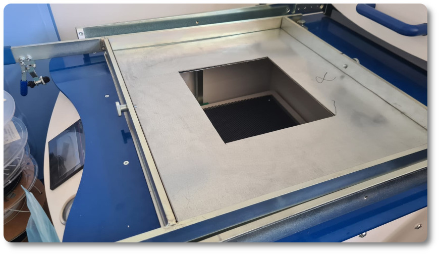
Another problem that arose was the element that went down. At first he wanted it to be transparent and to be able to work in the thermoformer. But the thermoformer could not mold a very large plate as required by the lamp that he had originally planned to develop.
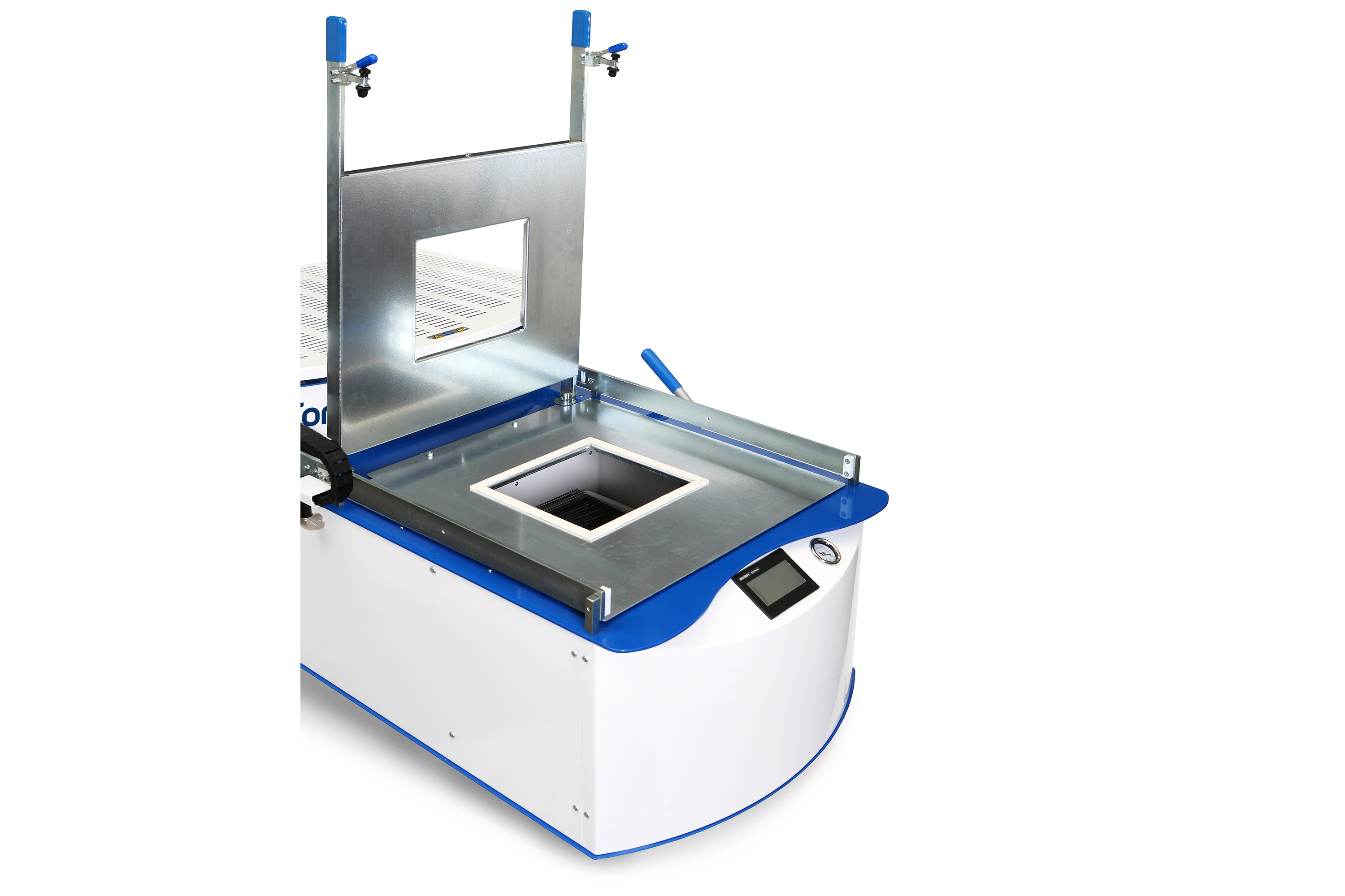
| Forming Area (mm / inches) | Sheet Size (mm / inches) | Max Depth of Draw | Max Material Thickness | Heating Zones | Heater Type | Width | Height | Depth | Power Consumption |
|---|---|---|---|---|---|---|---|---|---|
| 482 x 432mm / 19 x 17" | 508 x 457mm / 20 x 18" | 185mm / 7.3" | *6mm / 0.25" | 4 | Quartz | 720mm / 28.4" | 538mm / 21.2" | 1394mm / 54.9" | 3.2kW |
As can be seen in the characteristics of the thermoformer, the maximum size is 482 x 432 mm, the lamp plate was 600 mm. This topic left me a bit worried but I decided to solve it a little later.
Week3, for more information click here
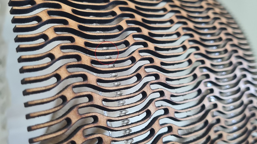
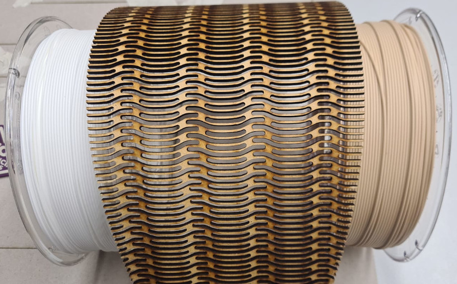
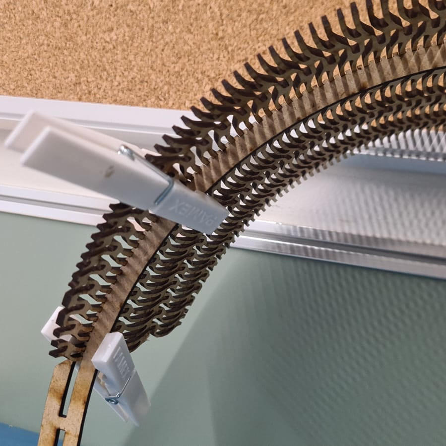
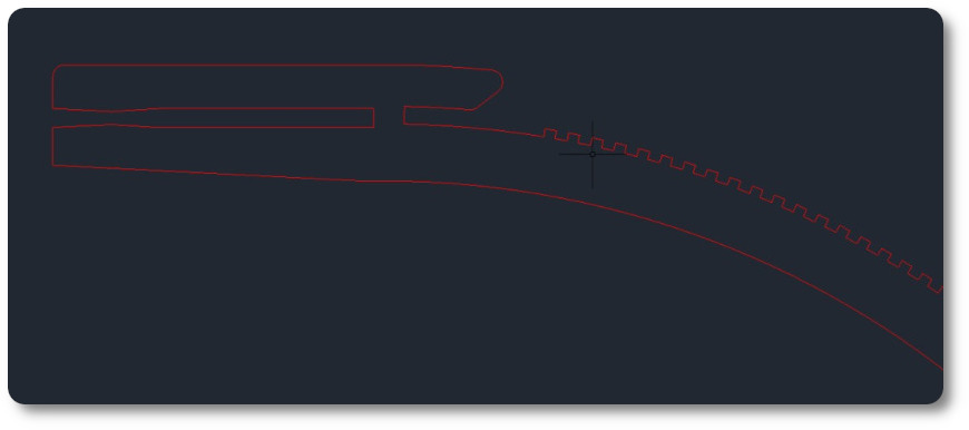
in the third week, we were working with COMPUTER CONTROLLED CUTTING, it was a very interesting week, from the first moment I understood that in my final work I wanted to adopt the laser cutter, of course I was not working on something close to the project that I have finally done but I loved the theme of elastic wood.
I was working and rehearsing with different patterns to see where I could place this material
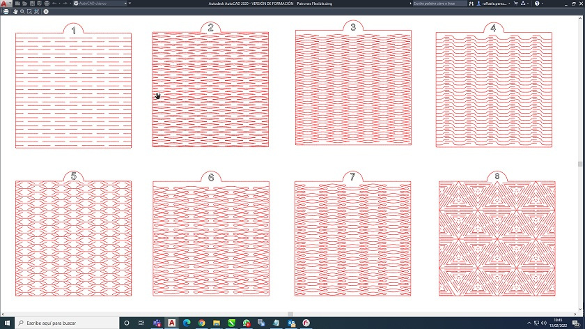
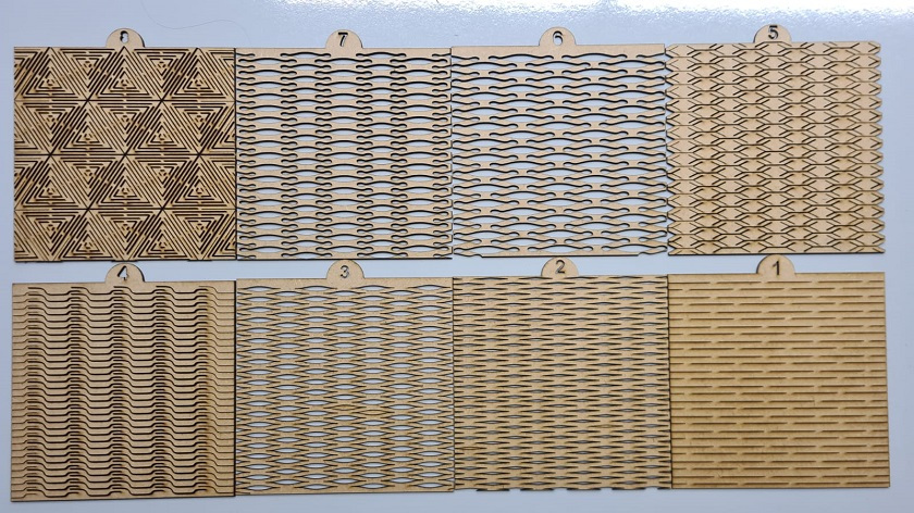
I liked them all very much, I tried many to study their adaptability to the curvature of the lamp.
Week4, for more information click here
In the fourth week we were working with electronic production. I had never worked with these things, my training did not allow me to enjoy this topic that today I recognize to be very interesting. I have to admit that although it is not a week that you can develop components of your lamp, it indirectly prepares you to understand about electronic boards SMD, programming codes and milling. Very interesting!!!
Week5, for more information click here
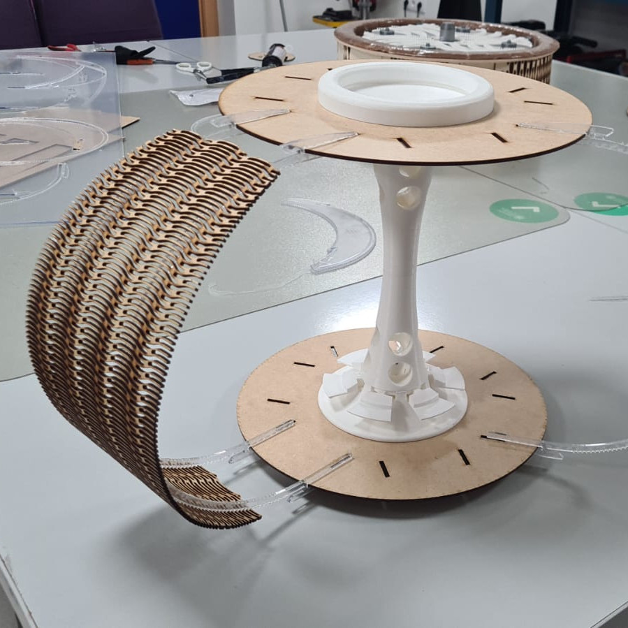
The fifth week, I think it was the most important for me. It was a key week, I learned to draw and print knots in one piece. In my final lamp it is a main element, without having studied this week, I would be unable to produce what I have done.
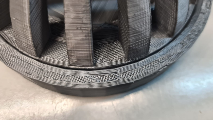
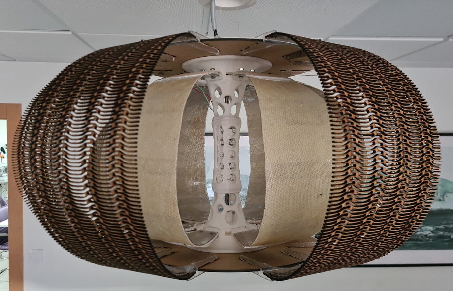
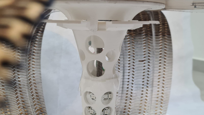
The central axis that I have made for the final lamp has a lot of functionalities. The lamp designed by Coderch is a lamp that cannot be examined inside. By opening the segments and revealing the interior, I had to imagine and design its interior. Its interior is made up of a central frame that allows the interior and exterior segments to rotate. It is a piece printed at once!!!!!!
At the same time it is the structure that holds all the parts, what a headache! How many hours did I start thinking for this segment to be: beautiful, mobile and strong!
here I leave some key images of the week
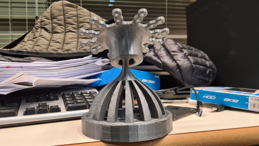 Articulated knot detail
 Z axis rotation
I am going to leave some key image so that you can see how it has been useful to me
Week6, for more information click here
The sixth week on electronic design, has been when I have started to work with the pins and understand how a microprocessor works.
Week8, for more information click here
The eighth week, it was an interesting week. I learned about programming, it is one of the fundamental subjects. I've been rehearsing on how to program the LED lights. At first it was difficult for me to adapt to the Arduino environment, libraries, examples, but since this is repeated every week, in the end you end up learning!
Week9, for more information click here
How can I detract from this week!!! without it I would not have been able to manufacture the inner segments!!! I learned about modes countermolds. In my final project I had to use it to create a foam mold!!!
Week10, for more information click here
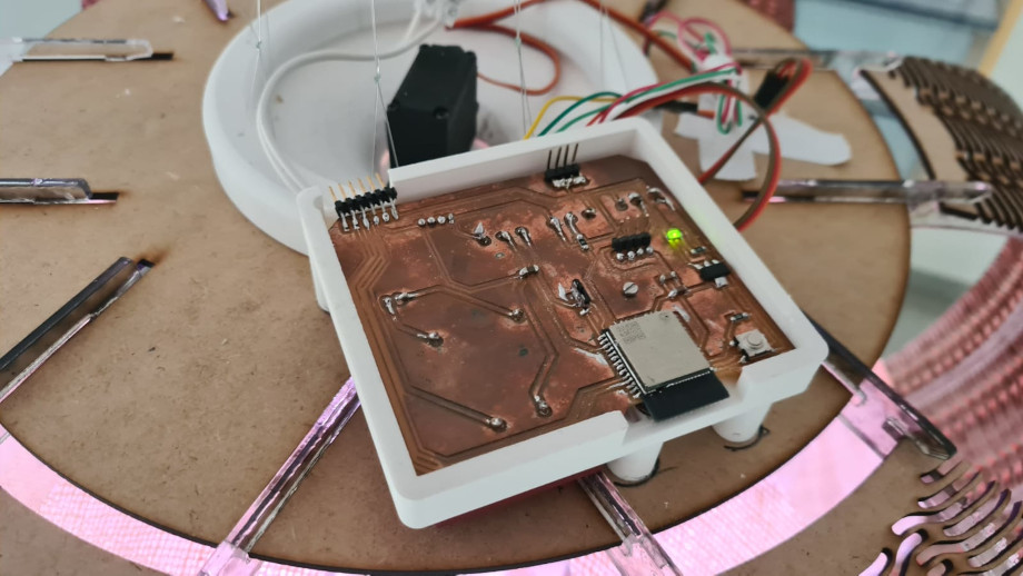
The tenth week on output devices was another key week, in it I made the electronic board that helped me to carry out multiple tests.
The design idea of this PCB was to have many pins and thus be able to introduce inputs and outputs on the same card.
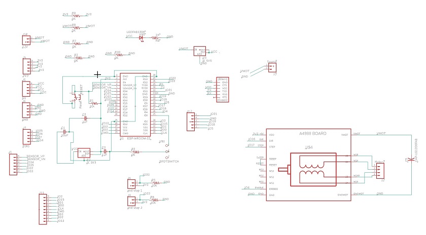
For the realization of this scheme I had to use 5 jumpers since there were many lines that were impossible to join.
To be able to work with esp in arduino it will be necessary to carry out a series of previous works. I leave a link where I found some instructions.
For more information about Wiki, clicking Here.
After having finished the design of the plate I will manufacture it.
For the realization of the board we have had to wait for the ESP32 Microprocessor. It hangs up due to gasoline has delayed the delivery 15 days, so now to work hard.
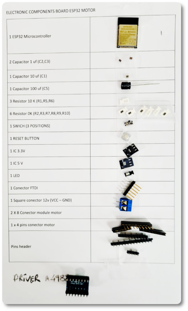
After having searched for the necessary components I am going to carry out.
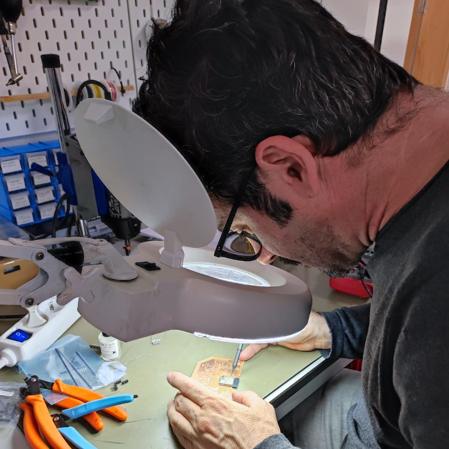
The board the first time I prepare such a large pcb and many components require me to modify them before putting them in.
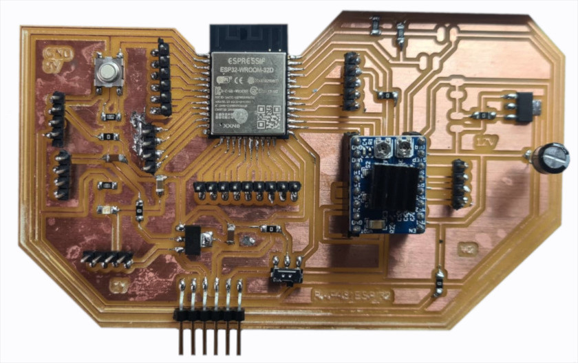
With it I have managed to understand the operation of a lot of devices, I would call it off-road PCB boards!!
Week11, for more information click here
This is a key week, a dress rehearsal of what was going to happen to me in the final project. A lot of work, a lot. It's a tremendous thing, especially if you don't have a group. Although my instructors have helped me, working alone this week is NOT COOL!!!
Week13, for more information click here
Another complicated but fun week. I really liked connecting the pCB via bluethoot and via Wifi. My lamp had to communicate via bluetooth so I paid a lot of attention to the subject. It helped me a lot, I began to understand how to connect via bluetooth and what it means to connect with ESP 32
Week14, for more information click here
Each week that I am advancing, I understand that everything that I am lighting here will serve me for my lamp. Specifically, this week, I worked on the development of an application for smartphones, I focused my work on the use of the light sensor and LED lights. I loved learning how to develop the application and that it will communicate with the board through the code written in the arduino IDE. It took me a long time to learn how to control the intensity of the light. But in the end I got it and I ended up very happy.
The application was made up of some elements that I was going to use in my smart lamp.
Week15, for more information click here
Key week for the development of my final project. In this week, I will change everything, except the functionalities that will remain the same.
I needed some advice and I spoke with my friend Pedro Garcia, professor of architecture at the University of Cartagena. He told me that he really liked a lamp, a lamp designed by the Catalan architect Coderch. My reaction was immediate, I needed to look for it and know what could be cool in the design of the lamp.
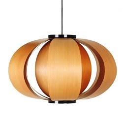
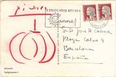
I really liked the design, it was simple and effective. From what I have been able to find out on the internet it seems that the source of inspiration is a pumpkin.
Among the stories that are told, there is one that deserves to be told. It seems that the architect, after having finished the manufacture of the lamp, sent a copy to mount to his friends and architects and artists of the time.
He also sent a copy to Picasso. The artist sent him a postcard with the design of the lamp as recognition.
Well, I'm going to post the weekly schedule and I'm going to work on the weekly homework. I have thought of making a petal of the lamp with the thermoformer. We hope everything goes well for me!!!!
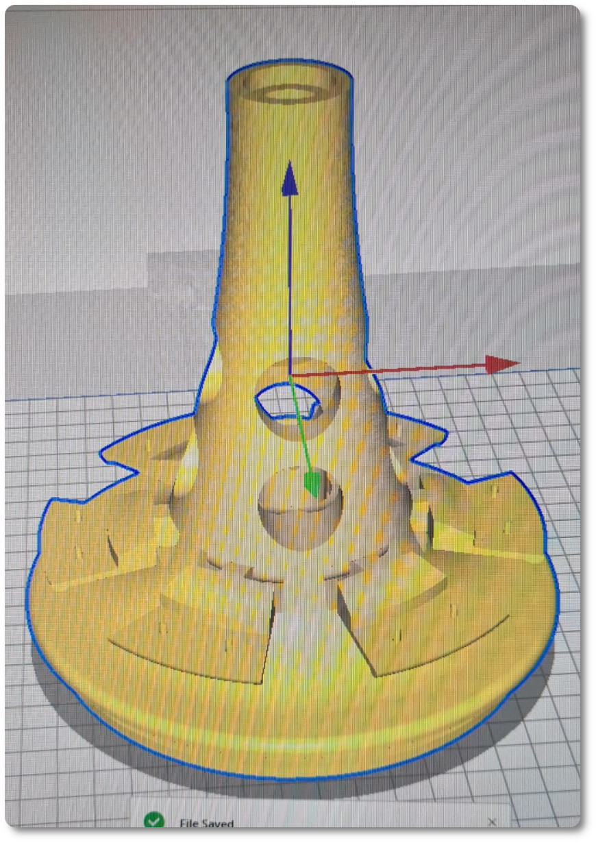
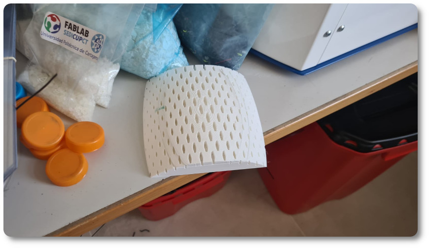
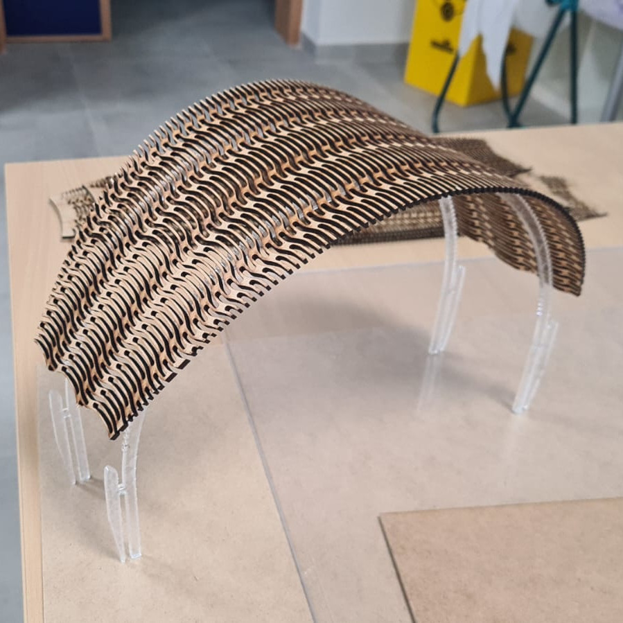
Before starting with the design of the petal of the lamp, I had to have a clearer idea about the final design of my lamp, so I drew the outer petal first in order to be able to design an inner petal that would be integrated with the design of the whole.
I tried a lot of patterns, but none fit the design, and in other cases it just failed.
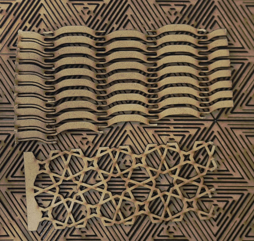
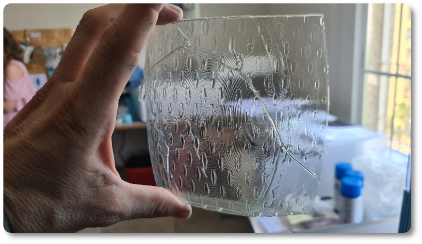
After many attempts, I understood that I had to make a pattern for this type of curvature and make it transparent enough to let light through.
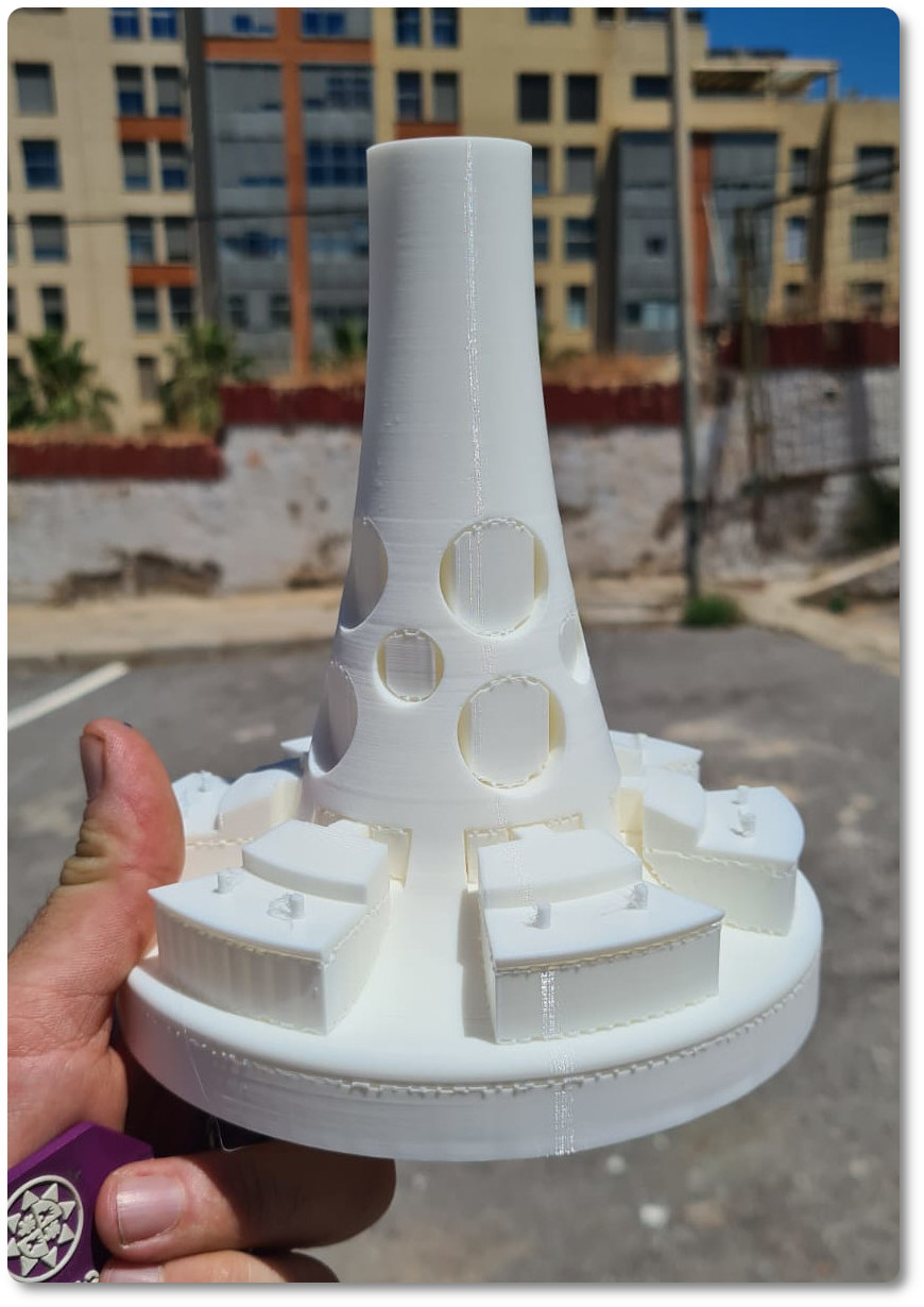
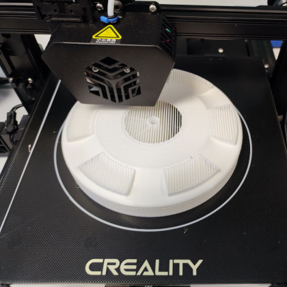
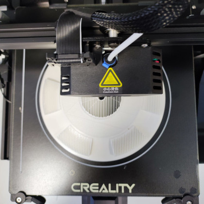
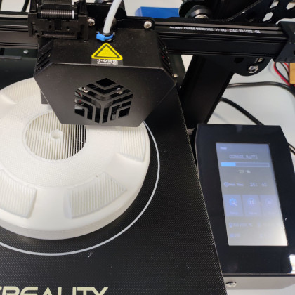
I did some more testing, testing the curves, transparency, and adaptability of the design to the inspiring image. In the end I decided that the best pattern is the one I leave in the photo. I will use it as my first petal and this week I will make the second one with the thermoformer.!!!!
Well, for the inner petal!!!! I hope my inspiration doesn't fail me!!!

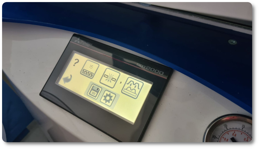
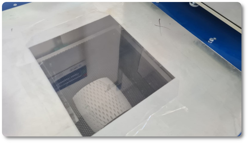
I did some tests with the thermoformer too, I leave some photos.
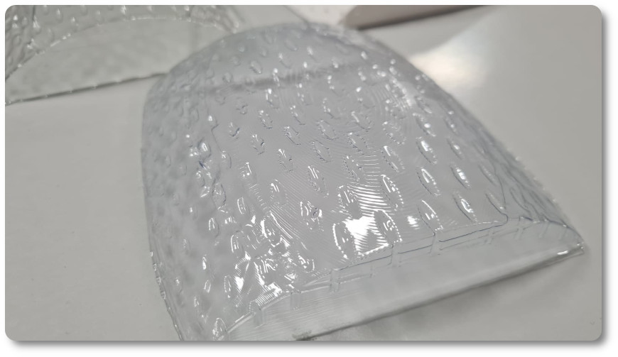
And this was the goal I achieved
The manufacturing process of the lamp!!!
This section, which is just as important in the development of the lamp, is going to be divided into three parts:
- Construction of the APP Inventor application
- Construction of the Arduino IDE Code for the communication between the lamp and the application
- Construction of the PCB Boards
- Construction of the parts of the physical parts of the lamp
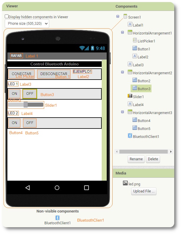
CONSTTRUCCON OF APP INVENTRO APLICATION
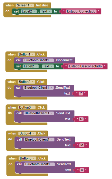
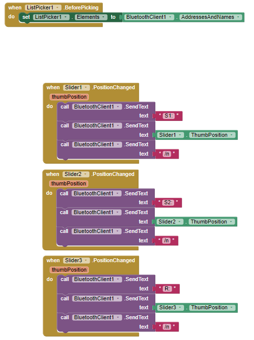
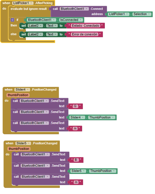
It is a very complex section, this app has a lot of features and you have to pay a lot of attention in the development. The trick of the application is based on sending letters or keywords to the ESP32 that has been designed and manufactured for this specific lamp.
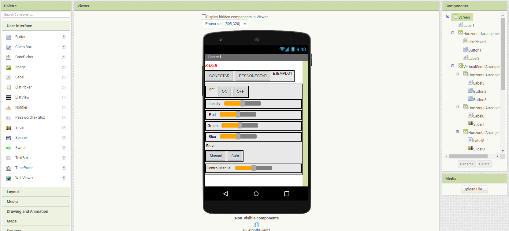
I also leave the programming blocks and the final files at the bottom of the page!!
CONSTRUCTION OF THE ARDUINO IDE CODE FOR THE COMMUNICATION BETWEEN THE LAMP AND THE APPLICATION
For the construction of aruino Ide, the code of the arduino IDE is the result of the development that has been built in the previous weeks. The code alone is not enough, as in all the code made to date, some libraries must be added. In this case, you have to add the "Adafruit_NeoPixel.h library," if you want to test my code, you have to click on this link and you will download the library.
- #include "BluetoothSerial.h"
- #if !defined(CONFIG_BT_ENABLED) || !defined(CONFIG_BLUEDROID_ENABLED)
- #error Bluetooth is not enabled! Please run `make menuconfig` to and enable it
- #endif
- BluetoothSerial SerialBT;
- #include <Adafruit_NeoPixel.h>
- #ifdef __AVR__
- #include "&" avr/power.h>
- #endif
- #define LedPin 15
- #define ServoPin 16
- #define LSensorPin 34
- //Leds control
- #define NUMPIXELS 30
- int BRIGHTNESS=255;
- int i_red=254;
- int i_blue=254;
- int i_green=254;
- Adafruit_NeoPixel pixels(NUMPIXELS, LedPin, NEO_GRB + NEO_KHZ800);
- int dutyCycle = 0;
- /* Setting PWM properties */
- const int PWMFreq = 50;
- const int PWMChannel = 0;
- const int PWMResolution = 8;
- bool b_autoServo=true;
- int servoMin=6;
- int servoMax=12;
- int LSensorValue = 0;
- int lsvMin=0;
- int lsvMax=1000;
- String recv = "";
- int MyP = 0;
- int MyI = 0;
- String subs[10];
- int ia=0;
- void setup() {
- Serial.begin(115200);
- pinMode(ServoPin, OUTPUT);
- pinMode(LedPin, OUTPUT);
- pinMode(LSensorPin, INPUT);
- SerialBT.begin("RAFAB"); //Bluetooth device name;
- Serial.println("ESP32_LED_Control");
- Serial.println("The device started, now you can pair it with bluetooth!
- ledcSetup(PWMChannel, PWMFreq, PWMResolution);
- /* Attach the LED PWM Channel to the GPIO Pin */
- ledcAttachPin(ServoPin, PWMChannel);
- ledcWrite(PWMChannel, dutyCycle);
- #if defined(__AVR_ATtiny85__) && (F_CPU == 16000000)
- clock_prescale_set(clock_div_1);
- #endif
- pixels.begin(); // INITIALIZE NeoPixel strip object (REQUIRED)
- pixels.setBrightness(BRIGHTNESS); // Set BRIGHTNESS to about 1/5 (max = 255)
- pixels.clear(); // Set all pixel colors to 'off'
- i_red=255; //initial value to red for RGB
- i_blue=255;// initial value to blue for RGB
- i_green=255;// initial value to green for RGB
- whiteLight();
- b_autoServo=true;//Iniciamos con el modo auto del servomotor segun el sensor de luz
- while(!SerialBT.connected(10000)) {
- Serial.println("Failed to connect. Make sure remote device is available and in range, then restart app.");
- }
- hello();
- }
- void loop() {
- if(b_autoServo){
- autoServo();
- }
- while (SerialBT.available())
- {
- recv = SerialBT.readStringUntil('\n');
- delay(1);
- Serial.println(recv);
- }
- if (recv == "Y")
- {
- lightOn();
- Serial.println("Turn on");
- }else if (recv == "N")
- {
- pixels.clear();
- delay(500);
- for(int i=0; i
- pixels.setPixelColor(i, pixels.Color(0, 0, 0));
- pixels.show();
- delay(50);
- }
- void loop() {
- Serial.println("Turn off");
- }else if (recv == "A")
- {
- b_autoServo=true;
- Serial.println("Auto mode");
- }else if (recv == "M")
- {
- b_autoServo=false;
- Serial.println("Manual mode");
- }else if(recv!="")
- {
- b_autoServo=false;
- Serial.println("Manual mode");
- }else if(recv!="")
- {
- Serial.println("analizando string");
- MyP=0;
- MyI = recv.indexOf(":",MyP);
- String s = recv.substring(MyP,MyI);
- Serial.println(s);
- MyP = MyI + 1;
- subs[0] = s;
- Serial.println("Substring1:");
- Serial.println(subs[0]);
- MyI = recv.indexOf(":",MyP);
- s = recv.substring(MyP,MyI);
- Serial.println(s);
- MyP = MyI + 1;
- subs[1] = s;
- Serial.println("Substring2:");
- Serial.println(subs[1]);
- if (subs[0] == "S1")
- {
- Serial.println("intensidad led: ");
- intensidad();
- }else if (subs[0] == "S2")
- {
- Serial.println("angulo servo: ");
- servo();
- }else if (subs[0] == "R")
- {
- Serial.println("red value of RGB: ");
- i_red=subs[1].toInt();
- Serial.println(i_red);
- lightOn();
- }else if (subs[0] == "G")
- {
- Serial.println("green value of RGB: ");
- i_green=subs[1].toInt();
- Serial.println(i_green);
- lightOn();
- }else if (subs[0] == "B")
- {
- Serial.println("blue value of RGB: ");
- i_blue=subs[1].toInt();
- Serial.println(i_blue);
- lightOn();
- }
- }
- recv = "";
- }
- void whiteLight(){
- pixels.clear(); // Set all pixel colors to 'off'
- for(int i=0; i
- pixels.setPixelColor(i, pixels.Color(254,254,254));
- pixels.show(); // Send the updated pixel colors to the hardware.
- delay(100); // Pause before next pass through loop
- }
- }
- void hello(){
- for(int r=0; r<3;r++){ //repeat 3 times
- for(int i=0; i<5; i++) { // For each nivel...
- pixels.clear(); // Set all pixel colors to 'off'
- for(int j=0;j<6;j++){
- if(r==0)pixels.setPixelColor(j+(i*6), pixels.Color(255, 0, 0));
- if(r==1)pixels.setPixelColor(j+(i*6), pixels.Color(0, 255, 0));
- if(r==2)pixels.setPixelColor(j+(i*6), pixels.Color(0, 0, 255));
- pixels.show(); // Send the updated pixel colors to the hardware.
- delay(30); // Pause before next pass through loop
- }
- }
- }
- whiteLight();
- }
- void lightOn(){
- pixels.clear(); // Set all pixel colors to 'off'
- for(int i=0; i
- pixels.setPixelColor(i, pixels.Color(i_red,i_green,i_blue));
- pixels.show();
- delay(30); // Pause before next pass through loop
- }
- }
- void intensidad(){
- delay(15);
- int value=subs[1].toInt();
- BRIGHTNESS=value;
- Serial.println(value);
- pixels.setBrightness(BRIGHTNESS); // Set BRIGHTNESS to about 1/5 (max = 255)
- recv = "";
- }
- void servo(){
- delay(15);
- recv="";
- int value=subs[1].toInt();
- if(value>servoMax){value=servoMax;}
- if(value
- ledcWrite(PWMChannel,value)
- Serial.println(value);
- }
- void autoServo(){
- LSensorValue = analogRead(LSensorPin);
- Serial.print("Light sensor value: ");
- Serial.print((float)LSensorValue);
- Serial.println(" of 4095");
- int value= servoMin + (servoMax-servoMin)*(lsvMin-LSensorValue)/(lsvMin-lsvMax);
- if(value>servoMax){value=servoMax;}
- if(value
- ledcWrite(PWMChannel,value);
- Serial.print("Servo value: ");
- Serial.println(value);
- delay(100);
- }
CONSTRUCTION OF THE PCB BOARDS
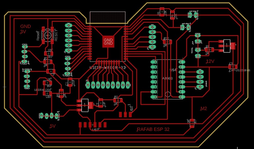
The design of the plate and its manufacture thanks to the previous weeks did not tell me much. I had a Badge to start from and it was just a matter of continuing to make it better.
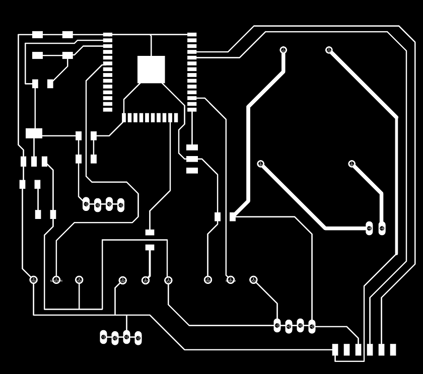
Apart from the images that I have used, I am also going to leave some screenshots of the work carried out in eagle and the files posted at the bottom of the page.
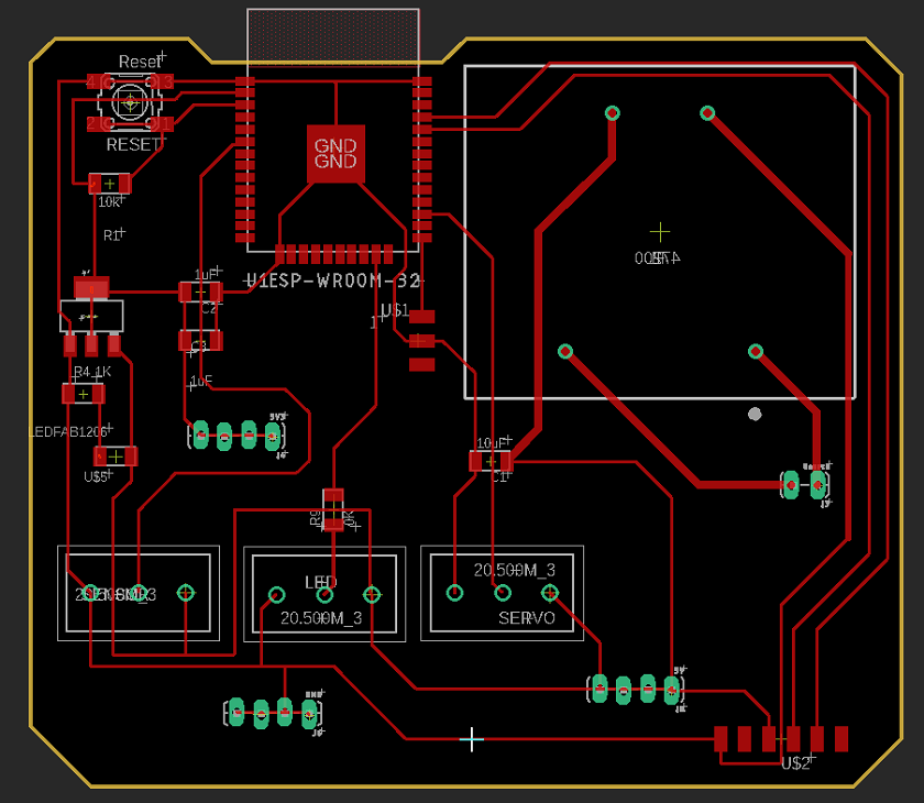
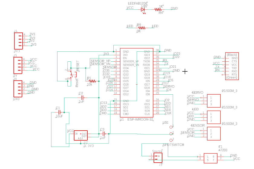
I will also leave some images where you can see the manufacturing process
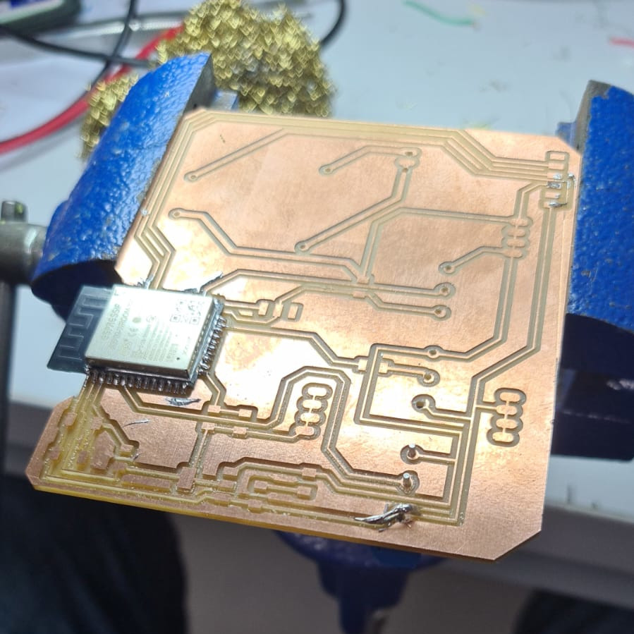
The plate did not have any problem and after having made it, it was programmed for its operation.
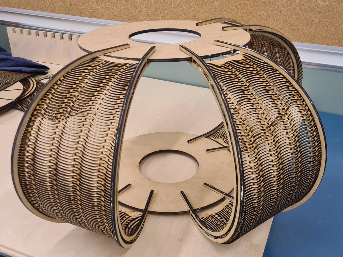
CONSTRUCTION OF THE PARTS OF THE PHYSICAL PARTS OF THE LAMP
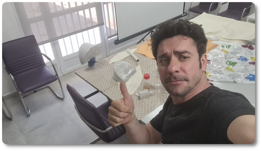
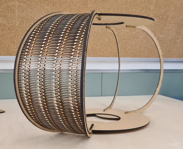
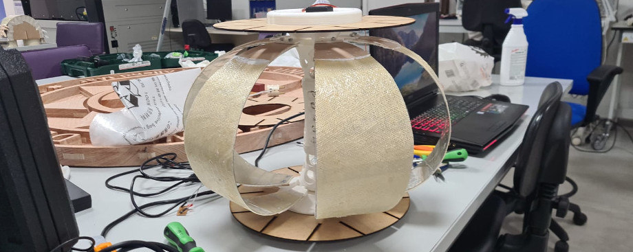
Well, finally, let's talk about the manufacture of the lamp. It is incredible the work that the manufacture of this object may have required. I have been working two weeks from 8:00 in the morning until 24:00 at night.
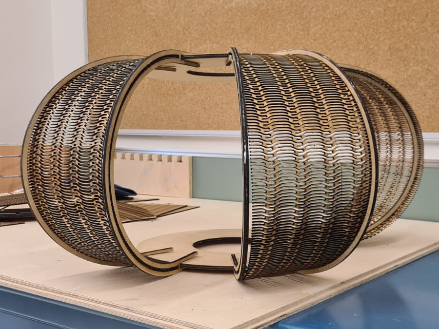
They have been the classic race against the clock, but seeing that everything works out in the end is a blow to self-esteem. She would never have imagined that she would look so pretty. Up close you can see how the materials come together wonderfully and seeing it work is a spectacle.
It was a spectacle to see her assembled. I've needed hours and hours of testing.
In this video you can see the test on led lights. Every time he was mounting the leds, he had to know that everything was working perfectly before positioning them and putting on a trim.
With this image I was testing which type of PLA color could have been better, I decided on a bone white, more natural to match wood and linen.
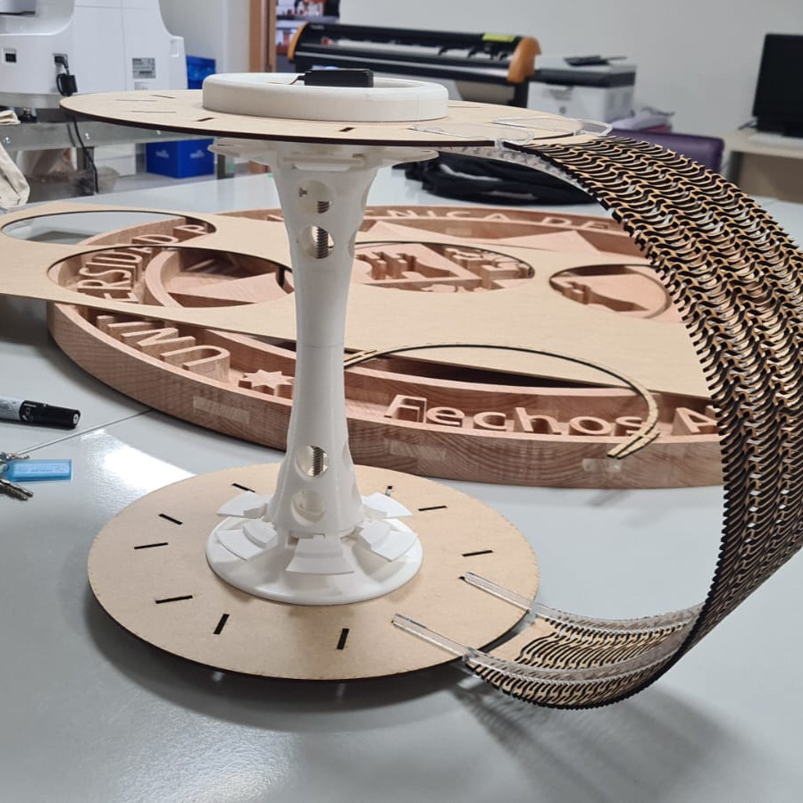
Here in this image I have all the elements before assembly. I drew and created some models for the drying of the interior elements on which we apply the epoxy resin. And what a beautiful image everything was perfect!!!!
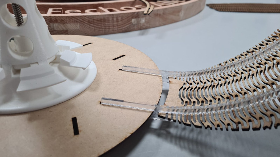
The methacrylate supports gave it such a light air and matched perfectly with the exterior segnmetnots carved with the laser.
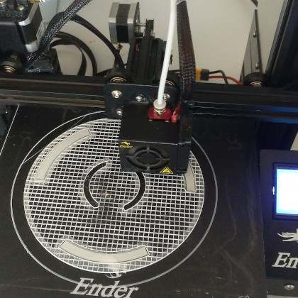
To get the center rack to work smoothly, I had to put three printers to work. I was afraid that if it could break I wouldn't have a spare, I had to work harder in case it had been necessary.
In this video you can see how it works.
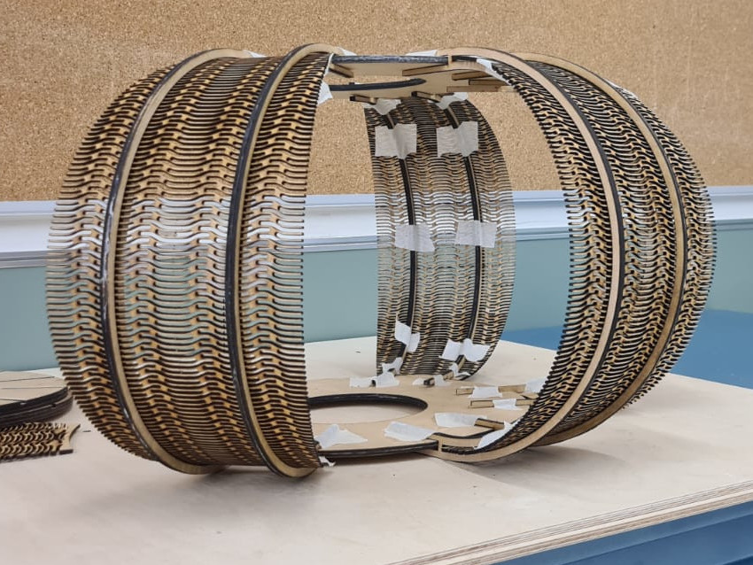
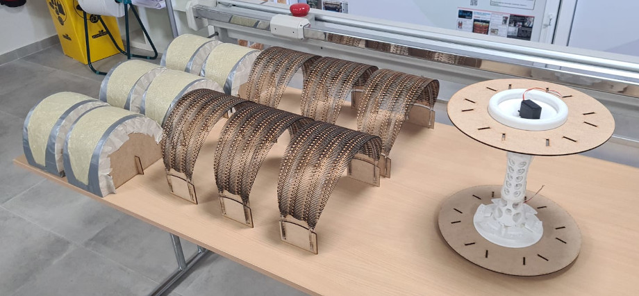
In these photos are the assembly tests
I am going to remember the work I have done with the alignment and fastening guides of the exterior elements. These guides, apart from being an element that will not occupy a fundamental place in the design, had to hold the outer segments made with the laser machine. they have been designed in such a way that the slots coincide with the spaces of the pattern of the outer segments. They have the same number of elements and when the elastic wood sheet is folded, they are embedded between them without the need for more elements that do not allow them to move.
Everything has been studied in detail so that they could be assembled and disassembled with the minimum effort.
I am going to upload a video of the cut with the laser machine of the cut of the methacrylate support.
The most outstanding characteristics of methacrylate sheets, also known as polymethyl methacrylate sheets or PMMA (according to its acronym in English), acquire great transparency and rigidity, as well as perfect resistance to any inclement weather.
Below, we list the most outstanding advantages and physical properties of this rigid plastic plate:
- 93% transparency
- High impact resistance, 10 to 20 times more than glass
- Long useful life
- A great lightness, since the material weighs half that of glass and has a density of about 1190 kg/m3
- It has a hardness similar to that of aluminum
- Great ease of machining and molding
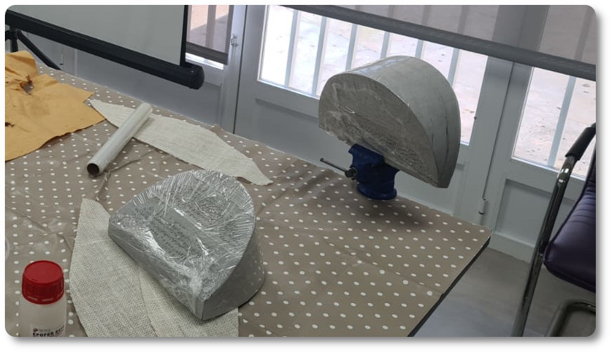
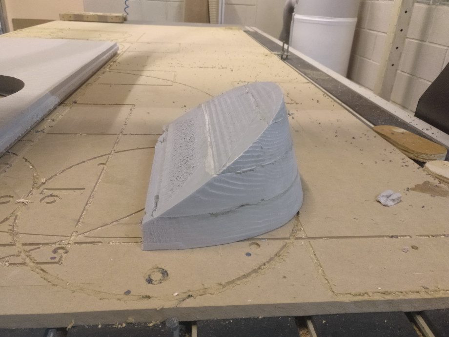
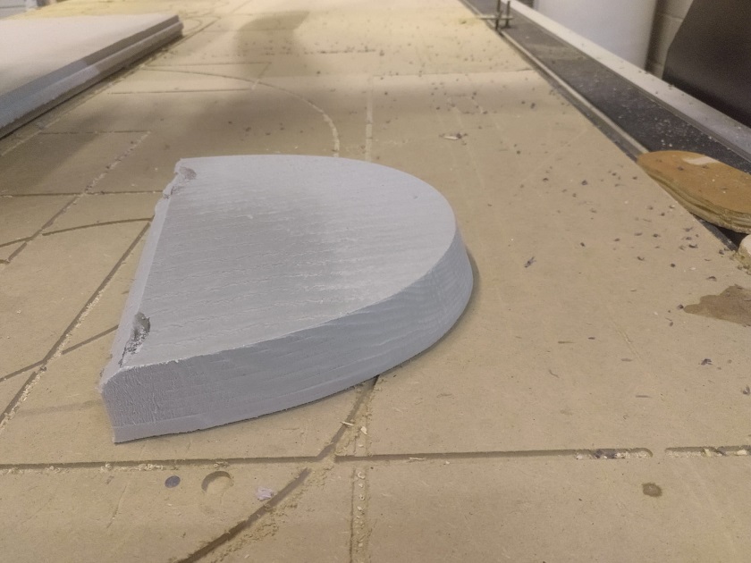
As I said at the beginning, in order to make the outer segments I had to use a mold. This mold was made with the milling machine.
I will leave step by step all the screenshots of the work in the aphire software!
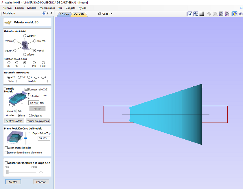
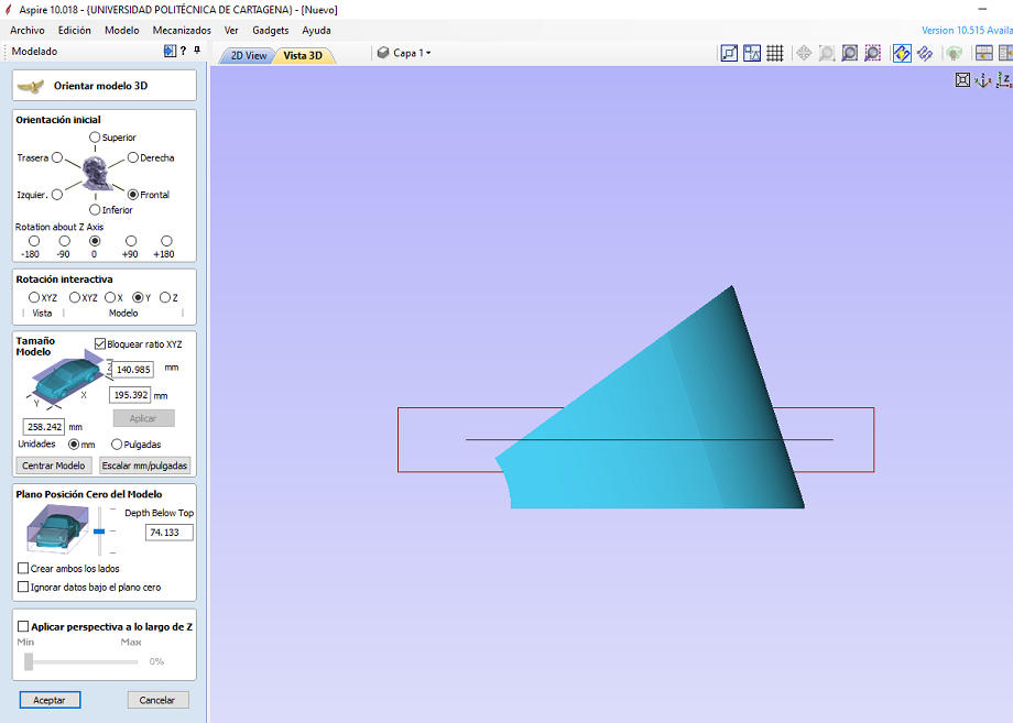
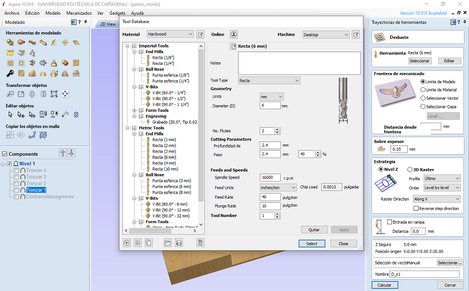
In order to make the mold I had to separate it into several pieces
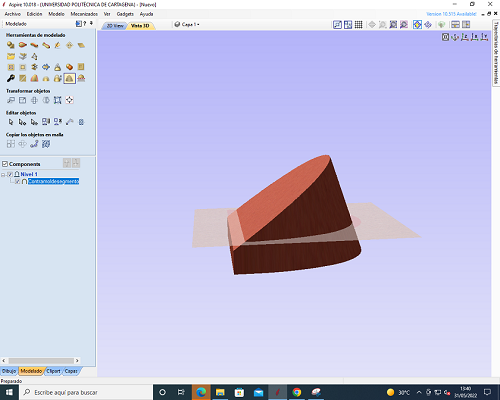
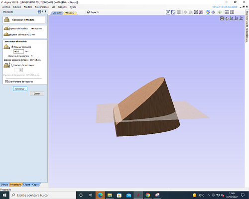
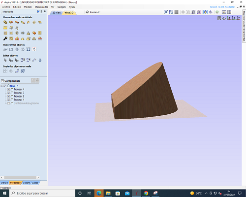
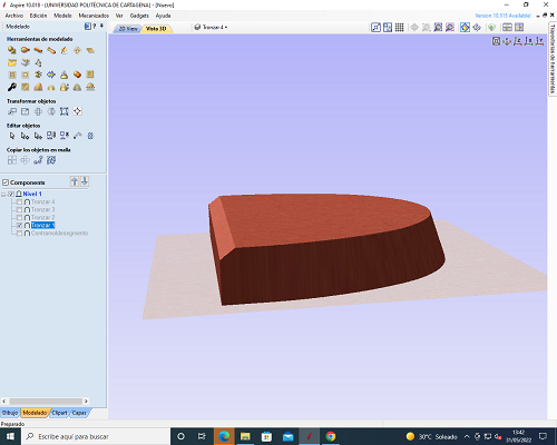
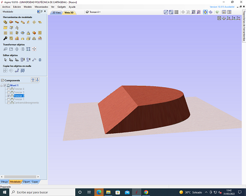
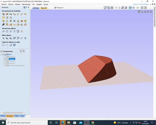
Here some images of the manufactured modes
I'll post a few more videos after the montage. Our tests!!
Here I am uploading the files that I have been making this week
Well, this is the manufacturing process that I have done in the last two weeks. It's as if I had gotten drunk, everything goes so fast that you isolate yourself from the world and mechanize everything. How many things have I experienced in these two weeks and surely over time I will remember!
CHARACTERISTIC OF THE MATERIALS USED
In this section I am going to give some information about the materials used, it is always good to know more about what we need to manufacture.
MDF (MEDIUM DENSITY FIBREBOARD)
For more information about Datasheet click here
- thickness= 3mm
- Length and Width +/- 2
- Squad ≤ 2mm
- Density Kg/m3 > 930
- Swelling in thickness 24 h ≤ 25
- Tensile strength ≥ 0.90 N/mm2
- Flexural strength ≥ 32 N/mm2
METHARCRYLATE
For more information about Datasheet click here
- Elongation at break Between 2.5 - 5%
- Rockwell Hardness On M scale: 92
- Tensile modulus 2400 - 3300 N/mm2
- Impact resistance Between 16 and 32 J*m-1
- Linear thermal expansion coefficient Between 70*10-6 and 77*10-6
- Working temperature From -40ºC to 50-90ºC
- Density 1.2 gcm-3
- Water absorption < 0.2%
- Excellent UV resistance. Does not yellow or crack
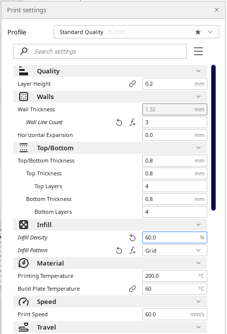
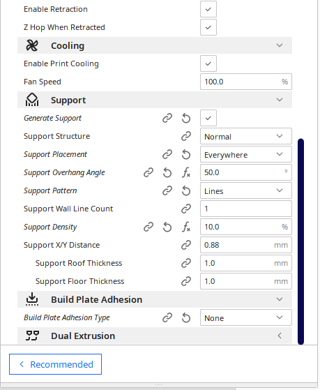
PLA PRINTING
For more information about Datasheet click here
Printing features
EPOXILAY 102
For more information about Datasheet click here
For more information about SAFETY DATA SHEET PART A here
For more information about SAFETY DATA SHEET PART B here
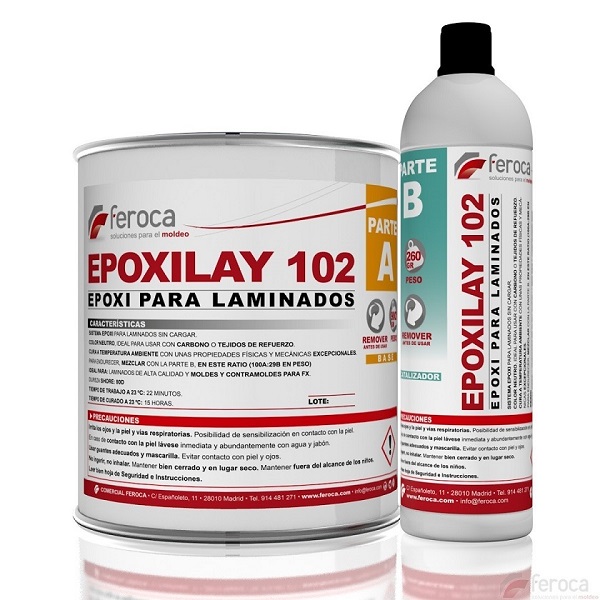
- Blend: A:B 3A:1B by Volume AND 100A:29B by Weight
- Colour: Light Yellow
- Curing Time: 15 hours.
- Flexural Modulus: 423,000 psi
- Mix viscosity: 650 cps
- Working Time: 22 min.
- Shore Hardness: 80D
- Tensile Strength: 8,180psi< 0.2%
- Specific Weight: 25
EXTRUDED POLYSTYRENE
This material has been used for the manufacture of the mold for the inner segment. For more information about Datasheet click here
- Density (in kg/m³): 32
- Edge Finish: Staggered
- Thickness (in mm): 40
- Length (in m): 1.25
- Width (in m): 0.6
- Area covered by the product (in m²): 0.75
- Reaction to fire standard Euroclass droplet: no
- Thermal resistance: R1 to R3
- Product brand: CHOVAFOAM


