WEEK 13
ON THIS PAGE WE WILL FIND A BRIEF DESCRIPTION OF MY JOB THROUGHOUT THE THIRTEENTH WEEK
GENERALITIES
Another week begins, and this time with more energy. The week before, he was still tired from working on the machine. I am going to do my work with my Rafab board, which has an ESP32 microprocessor with integrated WiFi module and Bluetooth with Low Energy mode and Classic mode. It also has plenty of pins for attaching various pre-made PCBs.
To do the tests I'm going to use the board I created last week using Bluetooth and WiFi. Also, I will use I2C communication to complete the Assessment, connect the ESP32 as a master, and use my HelloBoard with an ATTiny44 to connect as slaves. I would also like to connect more boards, but I don't know if I'm going to achieve it, it's the first time and I'll have to make things very clear to myself to take advantage of them for the future.
I would like to have a good documentation to be able to take advantage of it in the future. So let's work hard.
| Day | Wenesday | Thursday | Friday | Saturday | Sunday | Monday | Tuesday |
|---|---|---|---|---|---|---|---|
| 09:00 | |||||||
| 10:00 | Meeting CT | Assigments | Assigments | Assigments | Local Review | ||
| 11:00 | Meeting CT | Assigments | Assigments | Assigments | Local Review | ||
| 12:00 | Assigments | Assigments | Assigments | Assigments | write Documents | ||
| 13:00 | Assigments | Assigments | Assigments | Assigments | write Documents | Regional Review | |
| 14:00 | Assigments | Assigments | Assigments | Assigments | write Documents | Regional Review | |
| 15:00 | Fabacademy | Practice | Assigments | ||||
| 16:00 | Fabacademy | Practice | Assigments | Review Documents | |||
| 17:00 | Fabacademy | Practice | Assigments | Assigments | Assigments | write Documents | Review Documents |
| 18:00 | Fabacademy | Practice | Assigments | Assigments | Assigments | write Documents | Review Documents |
| 19:00 | Practice | Assigments | Assigments | Assigments | write Documents | Review Documents | |
| 20:00 | |||||||
| 21:00 | Assigments | Assigments | Assigments | write Documents | |||
| 22:00 | Assigments | Assigments | Assigments | write Documents | Write Documents | ||
| 23:00 | write Documents | Write Documents | |||||
| 24:00 | Tutorial | Tutorial | write Documents | ||||
| 01:00 | |||||||
| 02:00 |
This week has been very complicated, I have worked a lot. The connections were failing a lot, and I had to adjust everything to the minimum detail for the cards to work, the IC2 connections have a problem, you have to adjust everything to the minimum detail. I managed to understand all the programming and debugged the code a lot, it took me hours and hours of testing. I spent Thursday and Friday running thousands of tests. In the end, they worked fine. I do not know if it is the fault of my training as an architect that has failed me. But hey, in the end I'm happy. Since Monday this week was a holiday and I didn't have to go to work, I could afford to spend a lot of time on it.
PREPARING THE CONNECTION VIA BLUETOOTH BETWEEN ESP32 AND ANDROID
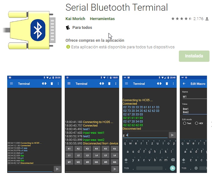
Since I am going to connect to the ESP32 with my mobile, I will need to find some ANDROID application that allows me to send test signals between the ESP32 and my mobile. Doing some research, I have found "Serial Bluetooth Terminal".
Here I leave the address to search for the application I have seen by clicking Here.
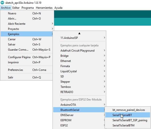
The first step is to install the application on the Smartphone, then I start the Arduino IDE to program my ESP32.
If I had to use the ESP32 for the first time, I would have to install the library, but since I have used this microprocessor before, and I have the library installed, it is no longer necessary!
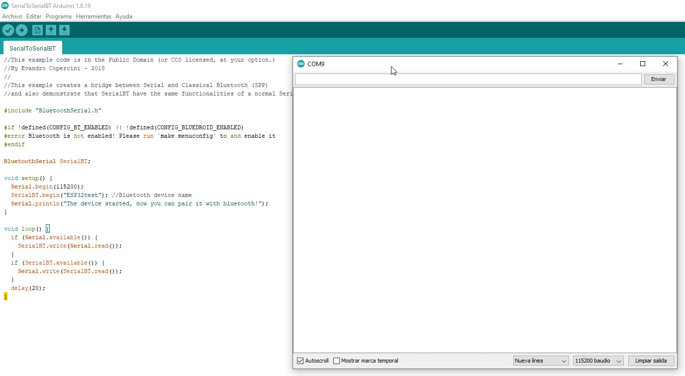
Once the program is loaded, check that everything is correct
- #include "BluetoothSerial.h"
- #if !defined(CONFIG_BT_ENABLED) || !defined(CONFIG_BLUEDROID_ENABLED)
- #error Bluetooth is not enabled! Please run `make menuconfig` to and enable it
- #endif
- BluetoothSerial SerialBT;
- void setup() {
- Serial.begin(115200);
- SerialBT.begin("ESP32test"); //Bluetooth device name
- Serial.println("The device started, now you can pair it with bluetooth!");
- }
- void loop() {
- if (Serial.available()) {
- SerialBT.write(Serial.read());
- }
- if (SerialBT.available()) {
- Serial.write(SerialBT.read());
- }
- delay(20);
- }
This code is responsible for establishing bidirectional communication between the computer and the mobile. It begins with the declaration of the Bluetooth library "BluetoothSerial.h" that is needed to execute the commands and that contains the necessary functions to establish communications through this type of channel.
The next step is to check that communication has been established.
You can also modify the communication speed.
Then with the SerialBT.write() and Serial.read() functions as the language suggests the data is sent and read through the serial port.
- if (Serial.disponible()) {
- SerialBT.write(Serial.read());
- }
With this condition check if it is receiving data on the serial port, if it receives data it sends it via Bluetooth.
- style="color:rgb(39, 74, 121)">if (SerialBT.disponible()) {
- Serial.write(SerialBT.read());
- }
THE CONNECTION TEST VIA BLUETOOTH BETWEEN THE ESP32 AND THE MOBILE
After I have uploaded the program to the microprocessor, I open the arduino serial monitor.
check if the program has been loaded by clicking on the reset
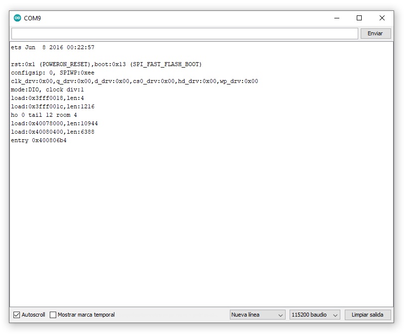
it works and this is a step forward
Now, I open the “Serial Bluetooth Terminal” application that I have previously installed on the Smartphone (with Smartphone Bluetooth enabled) and pair the devices.
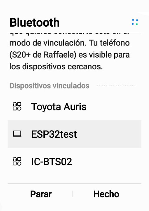
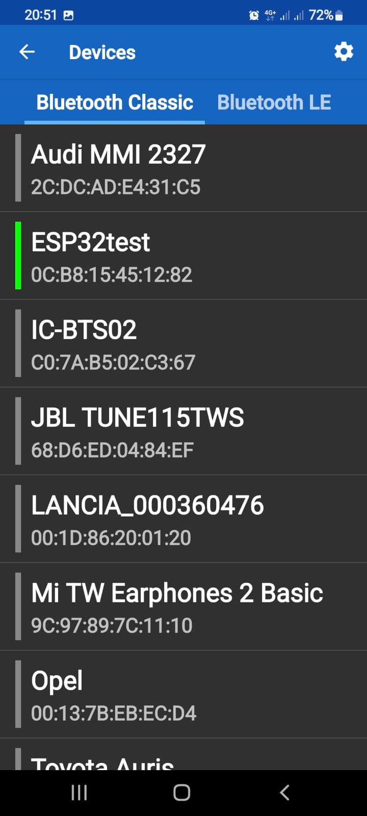
After having paired the devices via bluetooth I go to the application and search the devices
Indeed, I get the microprocessor and the mac of it, there are no problems, I'm going to try!!
I try to establish a connection and send data
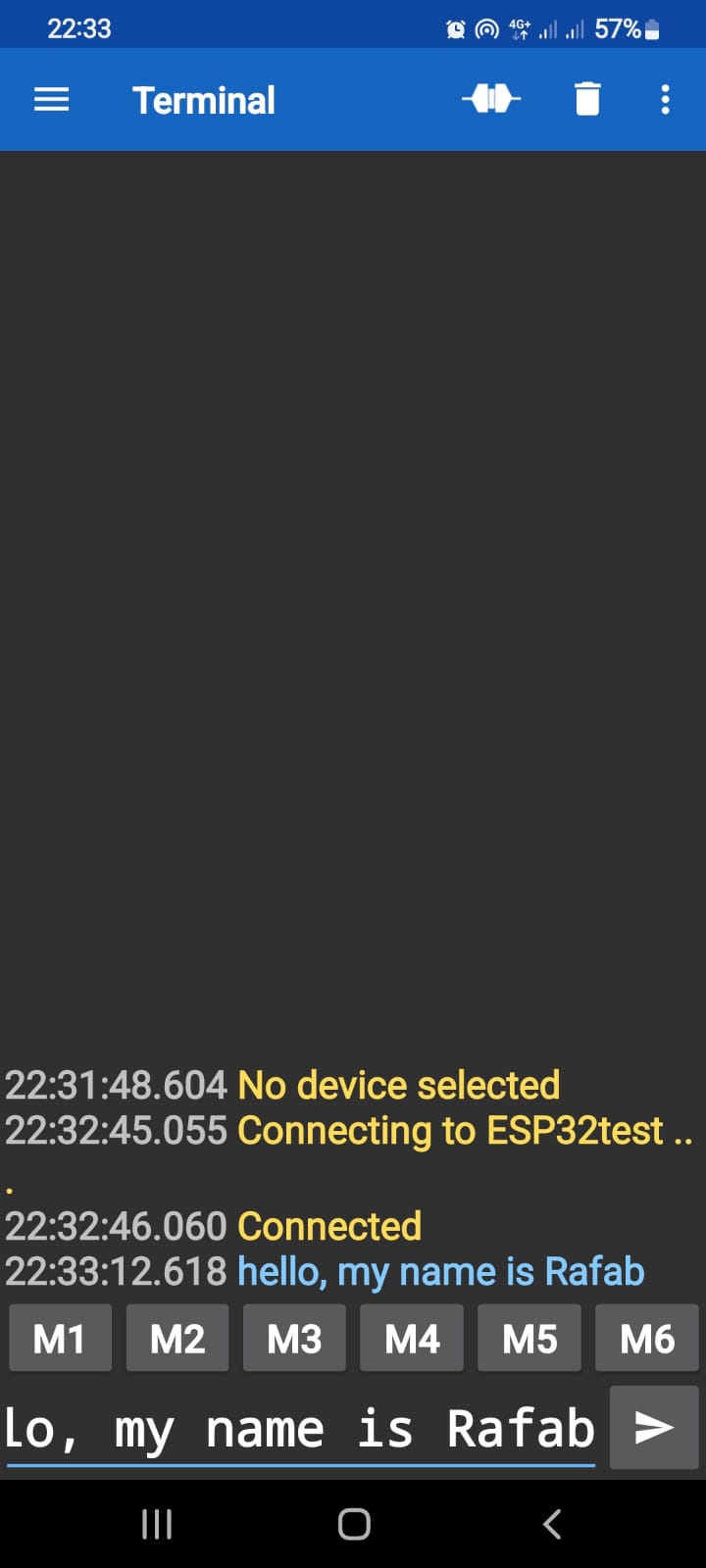
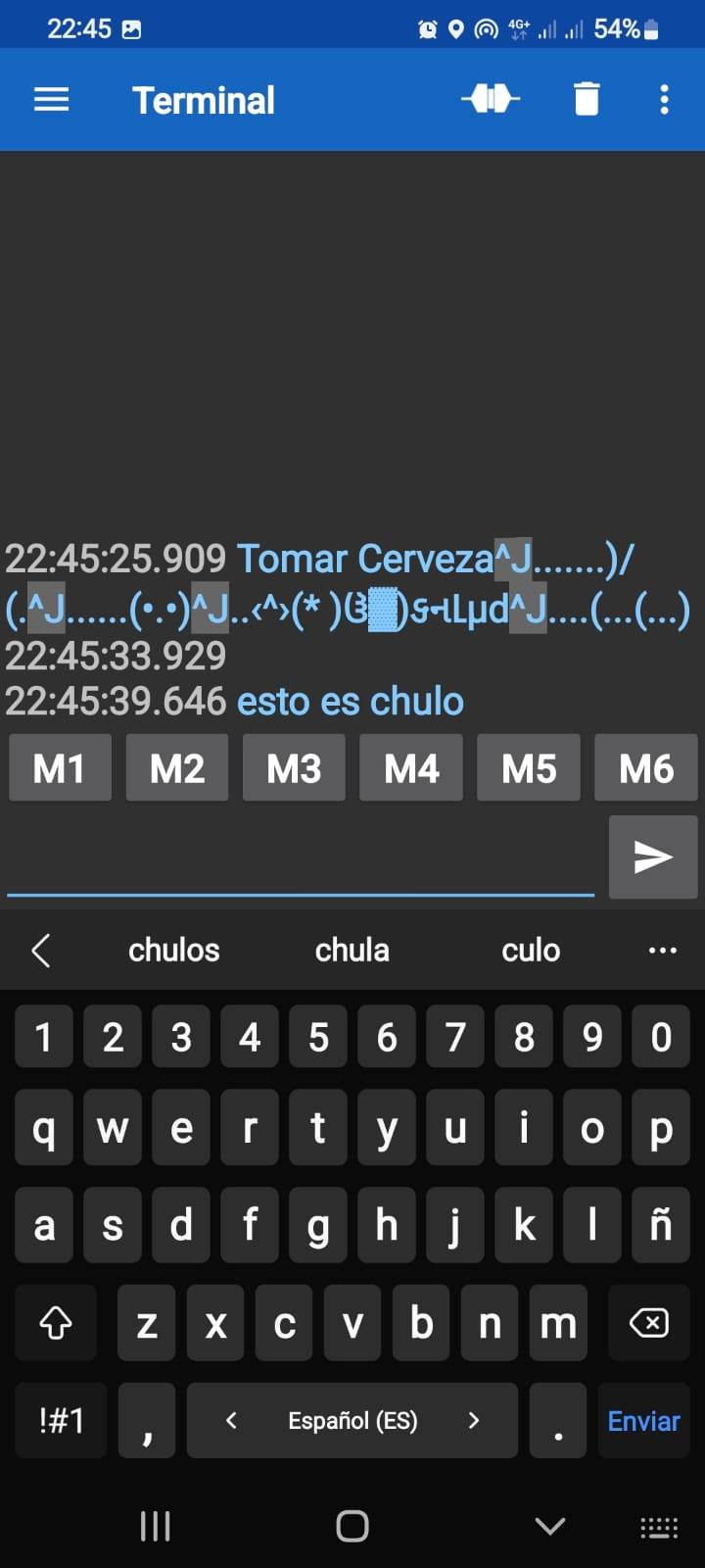
and this is the result!!!
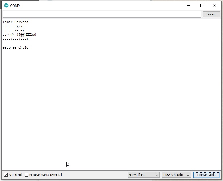
And this is the result!!! ready :).
I2C COMMUNICATIONS, THIS MUST BE WELL DOCUMENTED!
The ESP32, like other microprocessors, has an I2C protocol that allows its use to act as a master or as a slave with the help of cables.
I2C is a serial communication port and protocol, it defines the data frame and physical connections to transfer bits between 2 or more digital devices. The port includes two communication cables, SDA and SCL. In addition, the protocol allows up to 127 slave devices to be connected with these two lines, with speeds of up to 100, 400 and 1000 kbits/s. It is also known as IIC or TWI – Two Wire Interface.
The messages that are sent through an I2C port include, in addition to the information byte, an address of both the register and the sensor. For the information that is sent there is always a confirmation of receipt by the device. For this reason it is good to differentiate the different elements involved in this type of communication.
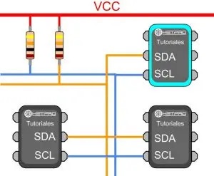
Whenever we talk about oral communication, it is understood that it is between two or more people. As a consequence, we can also indicate that in a digital communication there are different devices or elements. In the case of I2C there are two basic elements, a MASTER and a SLAVE. The figure shows a typical connection of three devices, the bus consists of two lines called, Serial DAta – SDA and Serial CLock – SCL. That is, Serial Data and Serial Clock. In particular, two resistors are connected to the bus in a pull-up arrangement, between 2.2K and 10K.
The I2C MASTER is responsible for controlling the clock cable, for its acronym in English called SCL – Serial CLock. In addition, the MAESTRO is in charge of starting and stopping the communication. Serial binary information is sent only through the serial data line or cable, in English it is called SDA – Serial DAta. Two Masters cannot use the same I2C port. It can work in two ways, as master-transmitter or master-receiver. Its main functions are:
- Start communication – S
- Send 7 bit address – ADDR
- Generate 1 Read or Write bit – R/W
- Send 8 bits of memory address
- Transmit 8 bits of data –
- Confirm receipt of data – ACK – ACKnowledged
- Generate No-receipt confirmation, NACK – No-ACKnowledged
- end communication
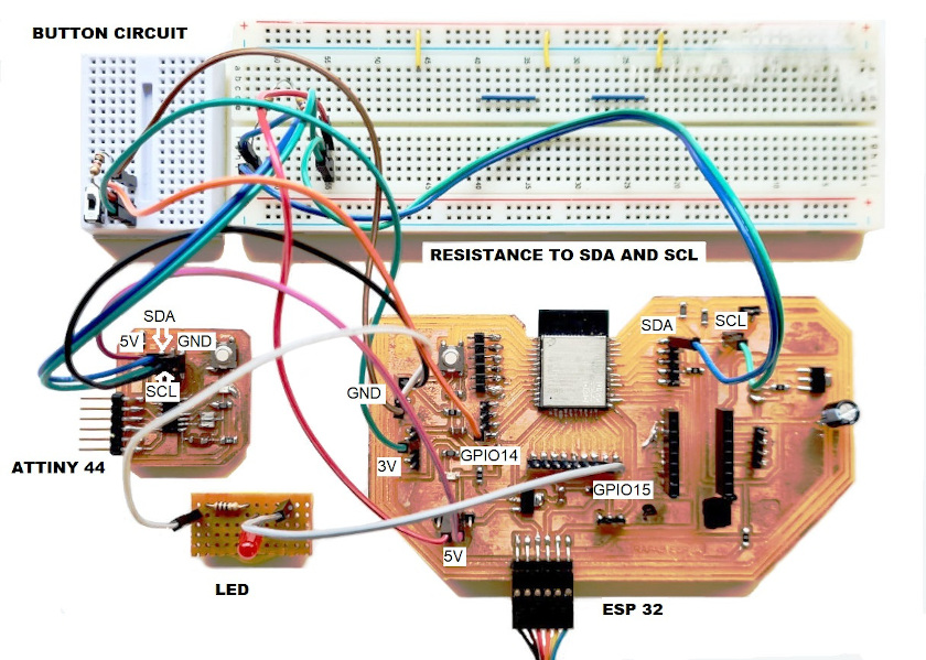
Long story short, to connect an I2C device to an ESP32, you need to connect the GNDs to each other, the SDA pins to SDA and the SCL pins to SCL and a VCC source, usually 3.3V or 5V.
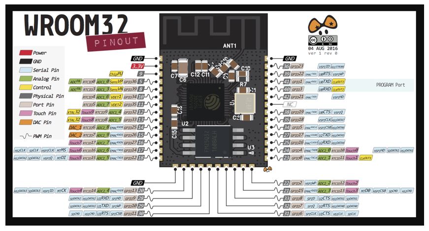
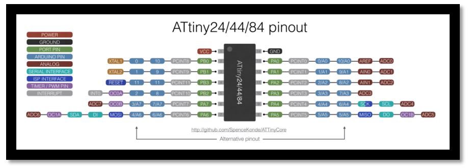
Before assembling the system, I am going to leave a pin diagram of the two PCBs so that you can check if there are any errors.
Schematic PINOUT of the ESP 32
Schematic PINOUT of the ATTiny44
This is the assembled schematic of the elements. the two PCBs and the led have been manufactured by me.
Now, I have to move on to programming. For the two devices to work, I have to load two libraries into the Arduino, one for the Master device and one for the Slave device.
Here I leave the download link for the TinyWireM.h Maestro library, clicking Here.
Here I leave the download link for the TinyWireS.h slave library, clicking Here.
For master board I have used the RAFAB-ESP32. To simulate the button, I have connected one wire to ground and one to the control pin, and one by hand both when I want to send the signal.
The programming for Master that I used is this:
- #include <Wire.h>
- #define slave1_ADDR 0x9
- int LED=15;
- int BUTTON=14;
- int previousButtonState=0;
- int ButtonState=0;
- void setup (){
- Wire.begin();
- pinMode(LED, OUTPUT);
- pinMode(BUTTON, INPUT);
- pinMode(22, OUTPUT);
- pinMode(21, OUTPUT);
- }
- void loop(){
- ButtonState = digitalRead(BUTTON);
- if (ButtonState != previousButtonState) {
- if(ButtonState==0){
- digitalWrite(LED, HIGH);
- Send_Button();
- }else{
- digitalWrite(LED, LOW);
- }
- }
- }
- void Send_Button(){
- Wire.beginTransmission(slave1_ADDR);
- Wire.write(1);
- Wire.endTransmission();
- delay(1000);
The programming for Slave that I used is this:
- #include <TinyWireS.h>
- #define slave1_ADDR 0x9
- int LED=8;
- bool LEDstate;
- void setup () {
- pinMode(4,INPUT); //scl
- pinMode(6,INPUT);//sda
- pinMode(LED,OUTPUT); //led;
- TinyWireS.begin(ADD_SLAVE);
- TinyWireS.onReceive(receiveEvent);
- TinyWireS.onRequest(requestEvent);
- digitalWrite(LED,LOW);
- LEDstate=true;
- Serial.begin(9600);
- Serial.print ("listo");
- }
- void loop (){
- TinyWireS_stop_check();
- Serial.println ("esprando");
- if (LEDstate==true){
- digitalWrite(LED,LOW);
- delay(200);
- }
- else digitalWrite(LED, HIGH);
- }
- void receiveEvent(){
- byte receivedData=0;
- Serial.print ("recibiendo: ");
- if(TinyWireS.available()){
- receivedData=TinyWireS.receive();
- if (receivedData==1){
- LEDstate=true;
- Serial.println ("1");
- digitalWrite(LED,HIGH);
- delay (3000);
- }
- else if (receivedData==0){
- LEDstate=false;
- }
- }
- }
- void requestEvent(){
- TinyWireS.send(0);
- }
Last step is to see if it works. I'm going to try my luck!!!
EVERYTHING WORKS!!!!!! I'm happy!!!!
YOU HAVE TO TRY IT WITH THE WIFI, TO SEE IF I GET IT!!!!
Now to complete the weekly task I am going to try to use the es32 as a wifi module.
The steps to follow are the following:
- Connect the Button on the GPIO 15.
- Compile the program on Arduino.
- Run the program on the PCB
- Open the monitor and see the established connections
- In the window the page where the on and off button is placed will be declared
- Turn on and off via Wi-Fi.
I'm going to put the programming language via wifi, you can copy and paste like the others!!!!
- #include <WiFi.h>
- #define LED 15
- String p="off";
- const char *ssid = "Cerveza";
- const char *password = "barata";
- WiFiServer server(80);
- void setup() {
- pinMode(LED, OUTPUT);
- digitalWrite(LED, LOW);
- Serial.begin(115200);
- Serial.println();
- Serial.println("Configurando");
- WiFi.begin(ssid, password);
- Serial.print("Conectandome");
- while (WiFi.status() != WL_CONNECTED)
- {
- delay(500);
- Serial.print(".");
- }
- if (LEDstate==true){
- digitalWrite(LED,LOW);
- delay(200);
- }
- else digitalWrite(LED, HIGH);
- }
- Serial.println();
- Serial.print("Conectado, La dirección IP es: ");
- Serial.println(WiFi.localIP());
- server.begin();
- Serial.println("Servidor iniciado");
- }
- void loop() {
- WiFiClient client = server.available();
- if (client) {
- Serial.println("Nuevo cliente.");
- String currentLine = "";
- while (client.connected()) {
- if (client.available()) {
- char c = client.read();
- Serial.write(c);
- if (c == '\n') {
- if (currentLine.length() == 0) {
- client.println("HTTP/1.1 200 OK");
- client.println("Content-type:text/html");
- client.println("Connection: close");
- client.println();
- client.println(" <!DOCTYPE html><html>");
- client.println("<head><meta name=\"viewport\" content=\"width=device-width, initial-scale=1\">");
- client.println("<link rel=\"icon\" href=\"data:,\">");
- client.println("<style>html{font-family: Helvetica; display: inline-block; margin: 0px auto; text-align: center;}");
- client.println(".button {border: none;color: white;padding: 15px 32px; text-align: center;");
- client.println("text-decoration: none;display: inline-block;font-size: 16px; margin: 4px 2px;cursor: pointer;}");
- client.println(".button1 {background-color: #4CAF50;} /* Green */");
- client.println(".button2 {background-color: #008CBA;} /* Blue */");
- client.println("</style></head>");
- client.print("<body><h1>WebServer con ESP32</h1>");
- if(p=="off"){
- client.println("<button type='button' class='button button1' onClick=location.href='/LED=ON'> ENCENDER </button><br><br>");
- }
- else{
- client.println("<button type='button' class='button button2' onClick=location.href='/LED=OFF'> APAGAR </button><br><br>");
- }
- client.print("