Send a message between two projects and reflect what you learned indivifually of group assignment
Group Assignment 2022 (Raffaele Alone)
On this page I am going to ask that an exception be made, the communication work between several plates I have presented on the individual page for various reasons. First of all, working alone in the Fablab I don't have the opportunity to compare with my colleagues, this has not been an obstacle, on the contrary it has motivated me. For this reason I have had to resort to the plates that I have been manufacturing in the fablab and communicate them with each other.
Of course, it would have been more useful to work with another colleague, but it has not been possible!
The ESP32, like other microprocessors, has an I2C protocol that allows its use to act as a master or as a slave with the help of cables.
I2C is a serial communication port and protocol, it defines the data frame and physical connections to transfer bits between 2 or more digital devices. The port includes two communication cables, SDA and SCL. In addition, the protocol allows up to 127 slave devices to be connected with these two lines, with speeds of up to 100, 400 and 1000 kbits/s. It is also known as IIC or TWI – Two Wire Interface.
The messages that are sent through an I2C port include, in addition to the information byte, an address of both the register and the sensor. For the information that is sent there is always a confirmation of receipt by the device. For this reason it is good to differentiate the different elements involved in this type of communication.
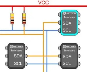
Whenever we talk about oral communication, it is understood that it is between two or more people. As a consequence, we can also indicate that in a digital communication there are different devices or elements. In the case of I2C there are two basic elements, a MASTER and a SLAVE. The figure shows a typical connection of three devices, the bus consists of two lines called, Serial DAta – SDA and Serial CLock – SCL. That is, Serial Data and Serial Clock. In particular, two resistors are connected to the bus in a pull-up arrangement, between 2.2K and 10K.
The I2C MASTER is responsible for controlling the clock cable, for its acronym in English called SCL – Serial CLock. In addition, the MAESTRO is in charge of starting and stopping the communication. Serial binary information is sent only through the serial data line or cable, in English it is called SDA – Serial DAta. Two Masters cannot use the same I2C port. It can work in two ways, as master-transmitter or master-receiver. Its main functions are:
- Start communication – S
- Send 7 bit address – ADDR
- Generate 1 Read or Write bit – R/W
- Send 8 bits of memory address
- Transmit 8 bits of data –
- Confirm receipt of data – ACK – ACKnowledged
- Generate No-receipt confirmation, NACK – No-ACKnowledged
- end communication
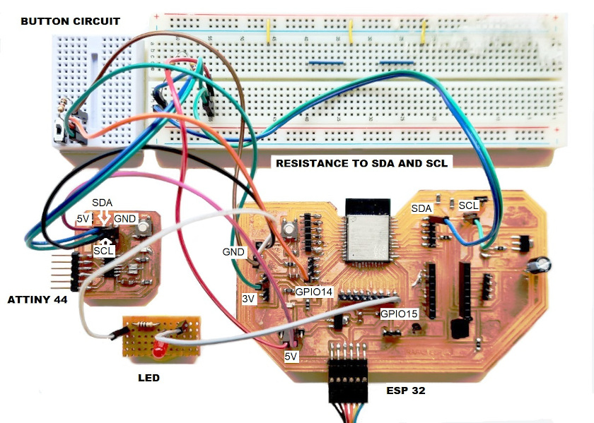
Long story short, to connect an I2C device to an ESP32, you need to connect the GNDs to each other, the SDA pins to SDA and the SCL pins to SCL and a VCC source, usually 3.3V or 5V.
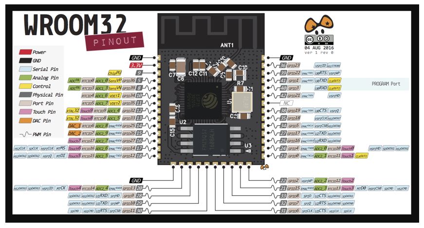
Before assembling the system, I am going to leave a pin diagram of the two PCBs so that you can check if there are any errors.
Schematic PINOUT of the ESP 32
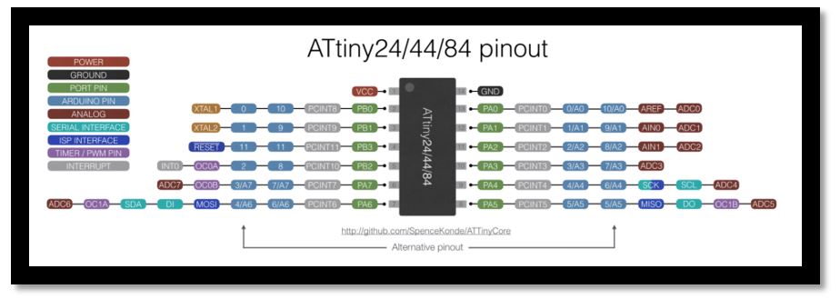
Schematic PINOUT of the ATTiny44
This is the assembled schematic of the elements. the two PCBs and the led have been manufactured by me.
Now, I have to move on to programming. For the two devices to work, I have to load two libraries into the Arduino, one for the Master device and one for the Slave device.
Here I leave the download link for the TinyWireM.h Maestro library, clicking Here.
Here I leave the download link for the TinyWireS.h slave library, clicking Here.
For master board I have used the RAFAB-ESP32. To simulate the button, I have connected one wire to ground and one to the control pin, and one by hand both when I want to send the signal.
The programming for Master that I used is this:
- #include <Wire.h>
- #define slave1_ADDR 0x9
- int LED=15;
- int BUTTON=14;
- int previousButtonState=0;
- int ButtonState=0;
- void setup (){
- Wire.begin();
- pinMode(LED, OUTPUT);
- pinMode(BUTTON, INPUT);
- pinMode(22, OUTPUT);
- pinMode(21, OUTPUT);
- }
- void loop(){
- ButtonState = digitalRead(BUTTON);
- if (ButtonState != previousButtonState) {
- if(ButtonState==0){
- digitalWrite(LED, HIGH);
- Send_Button();
- }else{
- digitalWrite(LED, LOW);
- }
- }
- }
- void Send_Button(){
- Wire.beginTransmission(slave1_ADDR);
- Wire.write(1);
- Wire.endTransmission();
- delay(1000);
The programming for Slave that I used is this:
- #include <TinyWireS.h>
- #define slave1_ADDR 0x9
- int LED=8;
- bool LEDstate;
- void setup () {
- pinMode(4,INPUT); //scl
- pinMode(6,INPUT);//sda
- pinMode(LED,OUTPUT); //led;
- TinyWireS.begin(ADD_SLAVE);
- TinyWireS.onReceive(receiveEvent);
- TinyWireS.onRequest(requestEvent);
- digitalWrite(LED,LOW);
- LEDstate=true;
- Serial.begin(9600);
- Serial.print ("listo");
- }
- void loop (){
- TinyWireS_stop_check();
- Serial.println ("esprando");
- if (LEDstate==true){
- digitalWrite(LED,LOW);
- delay(200);
- }
- else digitalWrite(LED, HIGH);
- }
- void receiveEvent(){
- byte receivedData=0;
- Serial.print ("recibiendo: ");
- if(TinyWireS.available()){
- receivedData=TinyWireS.receive();
- if (receivedData==1){
- LEDstate=true;
- Serial.println ("1");
- digitalWrite(LED,HIGH);
- delay (3000);
- }
- else if (receivedData==0){
- LEDstate=false;
- }
- }
- }
- void requestEvent(){
- TinyWireS.send(0);
- }
Last step is to see if it works. I'm going to try my luck!!!
EVERYTHING WORKS!!!!!! I'm happy!!!!
I2C is a serial communication port and protocol, it defines the data frame and physical connections to transfer bits between 2 digital devices. The port includes two communication cables, SDA and SCL. In addition, the protocol allows up to 127 slave devices to be connected with these two lines, with speeds of up to 100, 400 and 1000 kbits/s. It is also known as IIC or TWI – Two Wire Interface.
The I2C protocol is one of the most used to communicate with digital sensors, since unlike the Serial port, its architecture allows confirmation of the received data, within the same frame, among other advantages.
Los mensajes que se envían mediante un puerto I2C, incluye además del byte de información, una dirección tanto del registro como del sensor. Para la información que se envía siempre existe una confirmación de recepción por parte del dispositivo. Por esta razón es bueno diferenciar a los distintos elementos involucrados en este tipo de comunicación.
Whenever we talk about oral communication, it is understood that it is between two or more people. As a consequence, we can also indicate that in a digital communication there are different devices or elements. In the case of I2C there are two basic elements, a MASTER and a SLAVE. I reposition the figure at the beginning of the page for better clarification, it shows a typical connection of three devices, the bus consists of two lines called, Serial DAta – SDA and Serial CLock – SCL. That is, Serial Data and Serial Clock. In particular, two resistors are connected to the bus in a pull-up arrangement, between 2.2K and 10K.
El MAESTRO I2C se encarga de controlar al cable de reloj, por sus siglas en inglés llamada SCL – Serial CLock. Además el MAESTRO se encarga de iniciar y parar la comunicación. La información binaria serial se envía sólo por la línea o cable de datos seriales, en inglés se llama SDA – Serial DAta. Dos Maestros no pueden hacer uso de un mismo puerto I2C. Puede funcionar de dos maneras, como maestro-transmisor o maestro-receptor. Sus funciones principales son:
- Start communication – S
- Send 7 bit address – ADDR
- Generate 1 bit Read and Write – R/W
- Send 8 bits of memory address
- Transmit 8 bits of data –
- Confirm receipt of data – ACK – ACKnowledged
- Generate No-receipt confirmation, NACK – No-ACKnowledged
- end communication
The I2C SLAVE is usually a sensor. This element supplies information of interest to the MAESTRO. It can act in two ways: slave-transmitter or slave-receiver. An I2C slave device cannot generate the SCL signal. Its main functions are:
- Send information in 8-bit packets.
- Send receipt confirmations, ACK calls
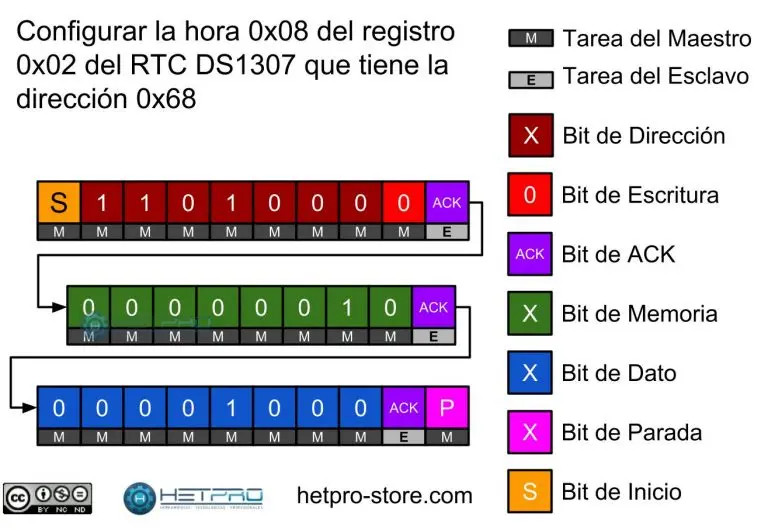
Example of registry settings:
To design data logger, it is necessary in some circumstances to use a Real Time Clock, RTC. A common RTC is the DS1307 which has a port to read and set the time. Figure-2 shows the data frame necessary to set the time to be 08 hrs. In order to find the sensor, you need to know its address. To determine the address there are 7 bits ( 2^7 = 128 ), hence up to 127 sensors can communicate with two lines, address 0 is a general call.
Then a read or write bit is required. So, this bit accompanies the 7-bit address. If the read/write bit is equal to 0, it means that the slave will be written. If this bit is equal to 1, then it means that it will be read. When the I2C Slave receives its address, that is when it is there, it responds with an acknowledgment (ACK). The slave waits for 8 bits of memory to be written and responds with an ACK. Subsequently, the slave waits for the master to send it the 8-bits of data corresponding to the configuration of the previous register and responds with an ACK. Finally the I2C-Master responds with an end of communication bit.
The I2C port and protocol is a very important topic for engineers who develop embedded systems. In addition to being able to connect up to 127 sensors, the I2C protocol allows managing secure communication between two digital devices. As a disadvantage we can mention the communication scheme. Because the scheme used is ONE-Master MANY-Slaves, this can generate latency in sending and receiving data from each of the slaves. This is because we can only use the I2C bus to communicate with one slave at a time. However, the I2C port is one of the most used in embedded applications. We can find I2C sensors in most digital electronic devices, from televisions, cell phones or laptops. In another tutorial I will mention examples of using I2C with different programming languages, such as Arduino, Mbed, assembler and C/C++. Another similar port is the serial port.