Electronics Production
Group Assignment 2022 (Raffaele Alone)
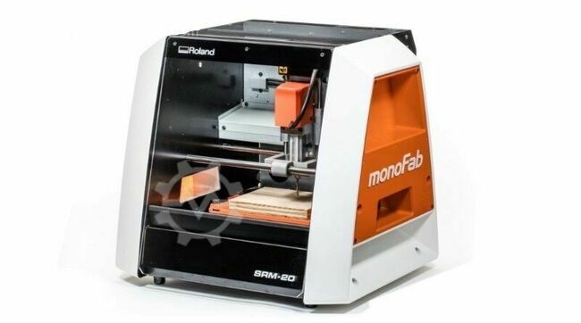
The group work has been carried out with the Roland monoFab SRM-20
| Cuttable Material | X, Y, and Z Operation Strokes | Workpiece table size | Distance From Collet Tip to Table | Loadable Workpiece Weight | X-, Y-, and Z-Axis Drive System | Operating Speed | Software Resolution | Mechanical Resolution | Spindle Motor | Spindle Rotation Speed | Cutting Tool Chuck | Interface | Control Command Sets |
|---|---|---|---|---|---|---|---|---|---|---|---|---|---|
| Modeling Wax, Chemical Wood, Foam, Acrylic, Poly acetate, ABS, PC board | 8 (X) x 6 (Y) x 2.38 (Z) inches, 203.2 (X) x 152.4 (Y) x 60.5 (Z) mm | 9.14 (X) x 6.17 (Y) inches, 232.2 (X) x 156.6 (Y) mm | Maximum, 5.15 in (130.75mm) | 4.4 lbs (2kg) | Stepping moto | 0.24 – 70.87inch/min, 6 – 1800mm/mi | 0.000039 inches/step (RML-1), 0.000039 inches/step (NC code), 0.01 mm/step (RML-1), 0.001mm/step (NC code) | 0.0000393 inches/step, 0.000998594 mm/step | DC motor Type 380 | Adjustable 3,000 – 7,000 rpm | Collet method | USB | RML-1, NC code |
As a small milling machine, the SRM-20 offers compact size and powerful functionality. Producing realistic parts and prototypes is made simple and convenient with a device that fits in an office-like environment. Engineered for optimum efficiency and productivity, the SRM-20 is a next-generation tabletop router featuring a micro-stepping motor drive system for clean, precise contour cuts, as well as a phenomenal 2X feed rate. faster than previous generations.
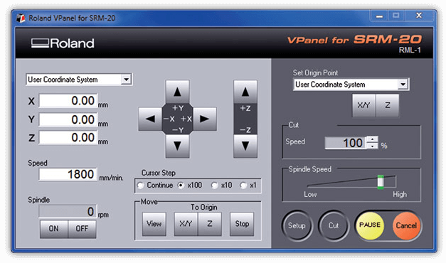
The SRM-20 was designed with a number of technological advancements that include a touch-button VPanel controller to regulate feed rate, spindle speed and milling on a complete X, Y, Z axes, and a new independent collet system that allows for faster setting of the Z-axis base point and quick tool changes.
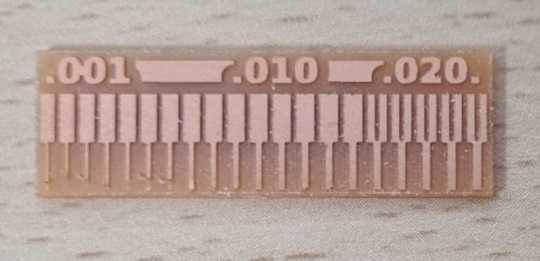
TIn group practice, a design has been milled on copper sheet to test the results obtained between the image to be made and the final product.
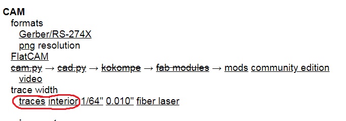
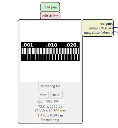
For the characterization of the milling machine, the images indicated in the weekly task sheet have been downloaded. I have to add one thing, there is an error, the inner image is changed with the outer one.
 Trace
Trace
 Interior
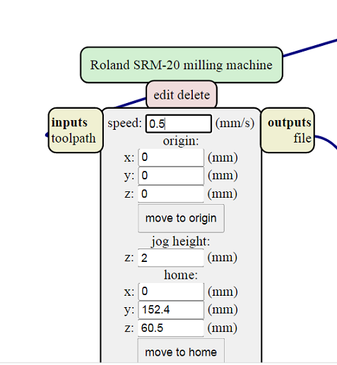
In the milling machine we will have to establish two types of milling. We are going to repeat the same steps that we did for milling the electronic board.
 Mods properties
 Mods properties
After working with the Mods parameter sheet, we will adjust all the values to perform the interior and exterior cut.
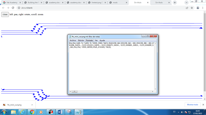
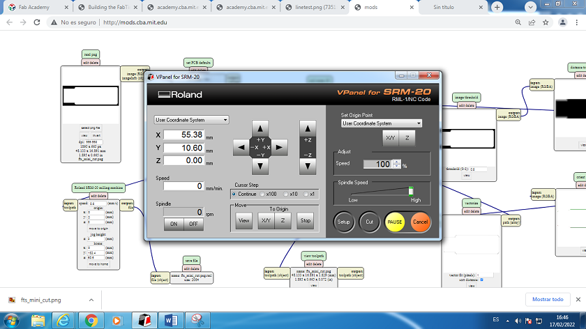
After having obtained the files from the Mods parameter sheet, what we will do is open the file in the mill software. To physically change the milling bits.
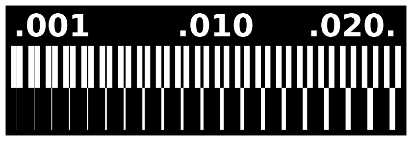
The result obtained tells us that the first 8 drawings up to 8 mm are of very poor quality. Between 9 and 15 improves quality but is still not acceptable. The milling machine is not capable of performing the internal drawing. From 16 mm the results are optimal.
To carry out the practice I have seen the work carried out by my instructors in previous years, they tried different speeds: 4,3,2,0.5mm/s and the best result was given with 0.5mm/s, for 0.8mm drill bits and 4 mm/s for 0.4 mm drill bits.
Although I am sure they did a good job, I have been doing some checks and the speed is inversely proportional to the width of the drill. They are special bits for CNC drilling.
My final data for Contour, are:
- Initial Depth= 0.0
- Feed rate: 0.5mm/s.
- 1/32 Inch drill bits = 0.0312 inch = 0.4 mm
- Depth of cut per pass in inch = 0.024
- Maximum depth in inch= 0.072
- Offset number = 1
- Final cutting depth: 0.2 mm.
- Spindle speed: 12000rpm.
My final data For Tracks, are:
- Initial Depth= 0.0
- Feed rate: 4mm/s.
- 1/32 Inch drill bits = 0.015624 inch = 0.8 mm
- Depth of cut per pass in inch = 0.004
- Maximum depth in inch= 0.004
- Offset number = 4
- Final cutting depth: 0.2 mm.
- Spindle speed: 12000rpm.
The materials that we have used in the FABLAB are FR1 and FR2.
If there is an FR4, there must be lower FRs, and their differences are as follows. FR1 is basically the same as FR2. FR1 has a higher TG of 130ºC instead of 105ºC for FR2. Tg (Glass Transition Temperature), or glass transition temperature, refers to the base material parameter that represents the temperature (°C) at which the base material becomes mechanically unstable. Tg is the value you need to ensure the mechanical stability of the PCB during the lifetime of the PCB.
Some laminate manufacturers that produce FR1 may not produce FR2 as the cost and usage are similar and it is not cost effective to have both. FR3 is also basically FR2. But instead of phenolic resin it uses an epoxy resin binder. And FR4 is the flame retardant that has been explained above.
What have I learned from the characterization of the milling machine???
I have learned a lot, to begin with, it is not a printer, you have limits, you have to ensure that the tracks have an adequate size for its operation. I already know that the fab labs libraries establish a series of parameters that help. Unfortunately this is not all, in the case of microprocessors the assembly drawing must be taken into account, not everything is possible. In my case, I drew a PCB with the ESP 32 microprocessor and the router was not able to split the pins. With the characterization it is possible to know to what extent it is capable of drawing interior clues. It was not the only fault, I also had problems with the connectors. The speed is another parameter to take into account, the drag can damage the tracks, the larger the cutter, the greater the danger of breaking the plate.