Input devices and something else......
Group Assignment 2022 (Raffaele Alone)
On this page I will be putting everything related to the measurement of digital input devices.
Phototransistors are tri-terminal (emitter, base, and collector) or bi-terminal (emitter, collector) semiconductor devices that have a light-sensitive base region. Although all transistors exhibit light sensitive nature, they are specially designed and optimized for photographic applications. They are made of diffusion or ion implantation and have much larger collector and base regions compared to ordinary transistors. These devices can be homojunctional or heterojunctional in structure, as shown in figures 1a and 1b, respectively.
In the case of homojunction phototransistors, the entire device will be made of a single type of material; either silicon or germanium. However, to increase their efficiency, phototransistors can be made of non-identical materials (Group III-V materials like GaAs) on both sides of the pn junction…leading to heterojunction devices. However, homojunction devices are used more often compared to heterosexual junction devices, as they are inexpensive.
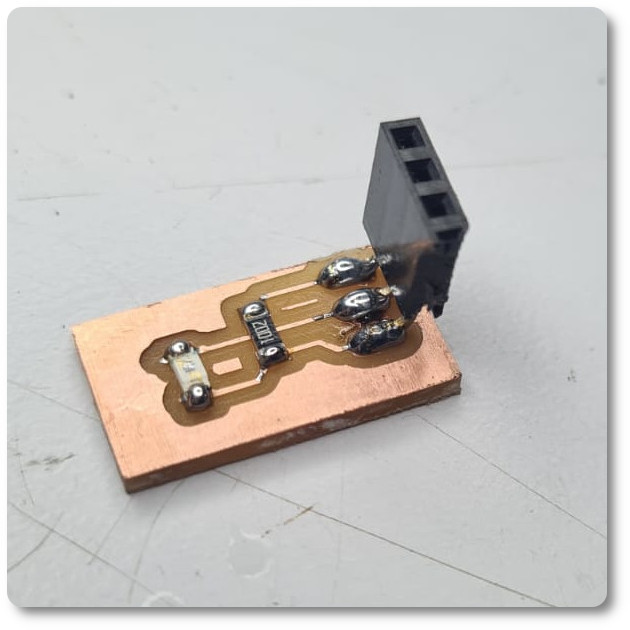
We have used the same Tektronix TDS 2004B oscilloscope to measure the signal from the PT15 sensor.
We use a card made with the ESP 32 to power a 5Vdc and Gnd circuit, connected to the two sensor power pins (Pin 14, Gnd).
Using the oscilloscope probe, we connect the clip to a pin of the output signal (Signal in my case Pin14) of the sensor made and the other crocodile clip to the Gnd pin of the PT15 sensor.
It is observed on the oscilloscope screen that the voltage signal decreases when a light source (moving flash) moves away and increases when it approaches the light source.
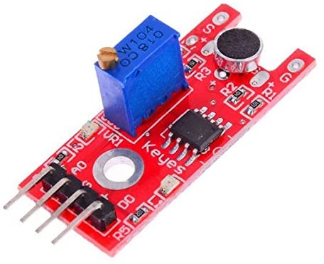
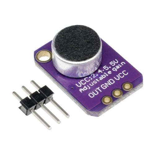
These modules incorporate a 20KHz electret microphone amplified by the MAX4466 and unamplified by the KY-038, a chip specifically designed for them.
For its use, it is recommended to use the most stable and clean source (the 3.3V in Arduino), the audio output will go through the OUT pin, which can be read with the ADC input of the microcontroller that is being used. The output wave has an offset of Vcc/2 and in a quiet environment the output will be a stable voltage of Vcc/2, it is a DC coupled output, if the audio input requires AC coupling you can add a 100uF capacitor in series between the output OUT and the input of your system.
We have used the same Tektronix TDS 2004B oscilloscope to measure the signal from aboth microphone.
We use a card made with the ESP 32 to power a 5Vdc and Gnd circuit, connected to the two sensor power pins (Pin 14, Gnd).
Using the oscilloscope probe, we connect the clip to a pin of the output signal (analogical signal in my case Pin14 with) of the sensor made and the other crocodile clip to the Gnd pin of the micropnone sensor.
It is observed on the oscilloscope screen that the voltage signal decreases when voice moves away and increases when it approaches the light source.