11. Input Devices
Editor’s note 2023
This was previously assignment 13.
Since I wrote my final project’s documentation more frequently than assignment documentation quite a lot of information related to both the sensor daughter boards and the general motherboard development can be found there.
On this page I’ll focus on how the sensor I picked works, how I interact with the sensor, how I programmed it and go into more detail on how I developed all the different versions of the MCU boards I made. I think it’s a bit pointless to talk a lot about what went wrong with the boards that didn’t work since me and my instructor just couldn’t debug the issues. Even with the help of Quentin Bolsee when I moved from the 328p to a SAMD21E.
Group Assignment - Probe an input device’s signal
Logic Analyzer and I2C
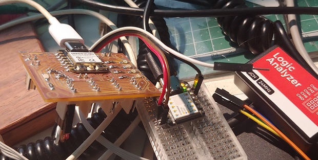
A Logic Analyzer is similar to an Oscilloscope but can automatically convert the signals read into human readable characters representing a given comunication protocol. In this case we’re looking for I2C byte queries and replies.
There are a bunch of cheap USB Logic Analyzer. I got mine from Digikey but I think it’s from Sparkfun.
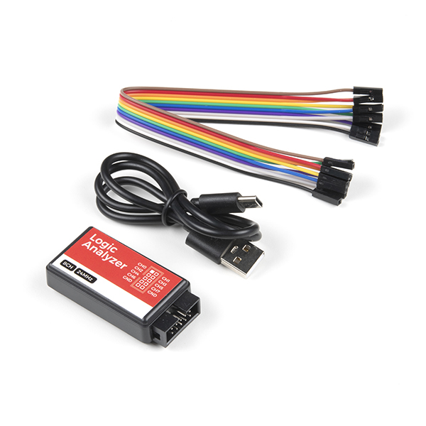
The software I used was made by Saleae, they make fancier analyzers but the software is kinda free to use. It’s called Logic 2 I’ve also heard about Sigrok as an Open Source alternative but haven’t tried it yet.
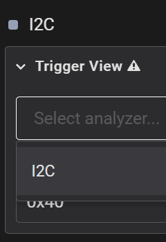
After installing we have to setup the analyzer protocol we want. On the right side…
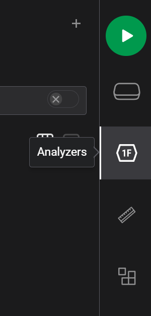
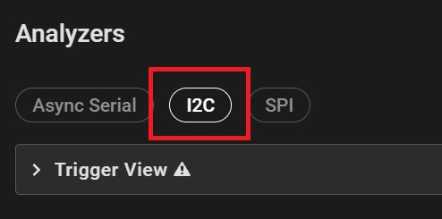
Pick I2C.
Assign SDA and SCL to whichever channel they’re connected to.
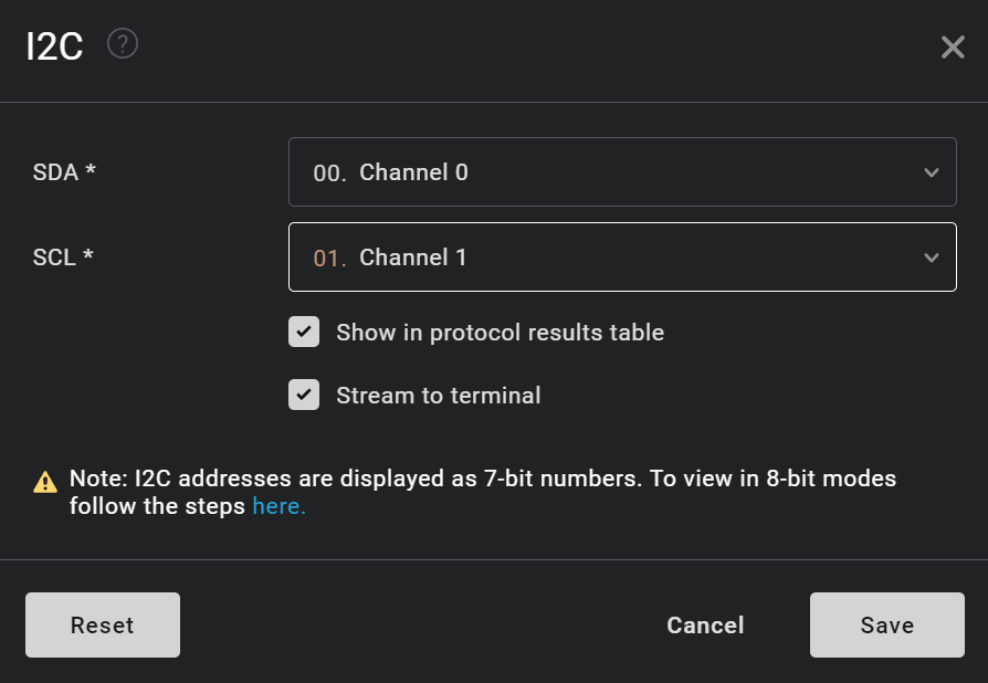
Triggers can help you find something quickly, like whenever the address 0x40 is called.
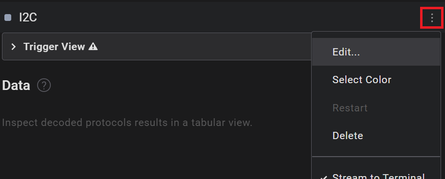
There’s a hamburger menu hidden that has a few options including editing the channels if you re-connected them differently.
Adrian goes into the Logic 2 software a bit more in his documentation.
And here’s my sensor at 0x10 replying to 3 queries, first one for status register at 0x0B and then a double query for both raw position registers at 0x0C and 0x0D.
Individual Assignment
The Sensor - AMS AS5600L
After doing a fair bit of research into possible sensors for my Coordinate Measuring Machine I settled for an AMS AS5600L. I talk about my research and a few more sensors in my Final Project Week 10 update
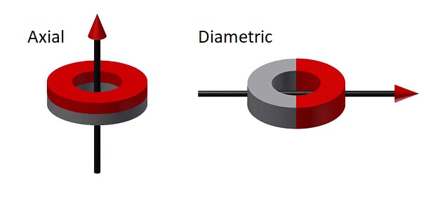
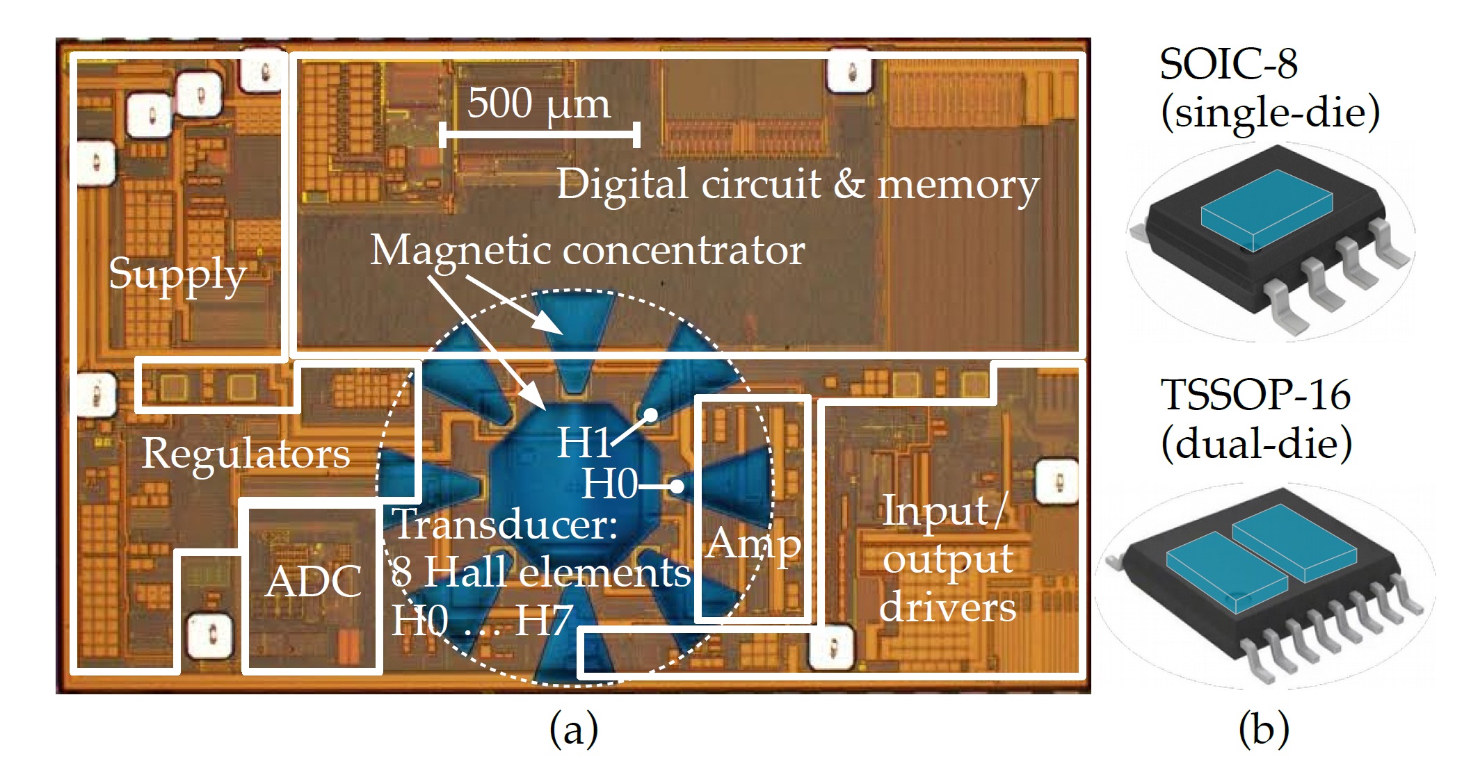
The AS5600L is a Magnetic On Axis Rotary Encoder. Which means it uses an array of Hall Effect Sensors to calculate the position of a diametric magnet. The array of magnetic sensors can feel the plane between each magnetic pole as it turns around on an axis.
I tried finding some cheap Magnetic Field Viewing Film to easily show the differences between regular and diametric magnets but gave up. This diagram will have to do:
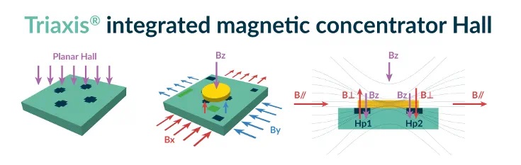
There are actually many different types of Hall Effect sensors to deal with different types of measurements. Melexis, another sensor brand has a nice page talking about that:
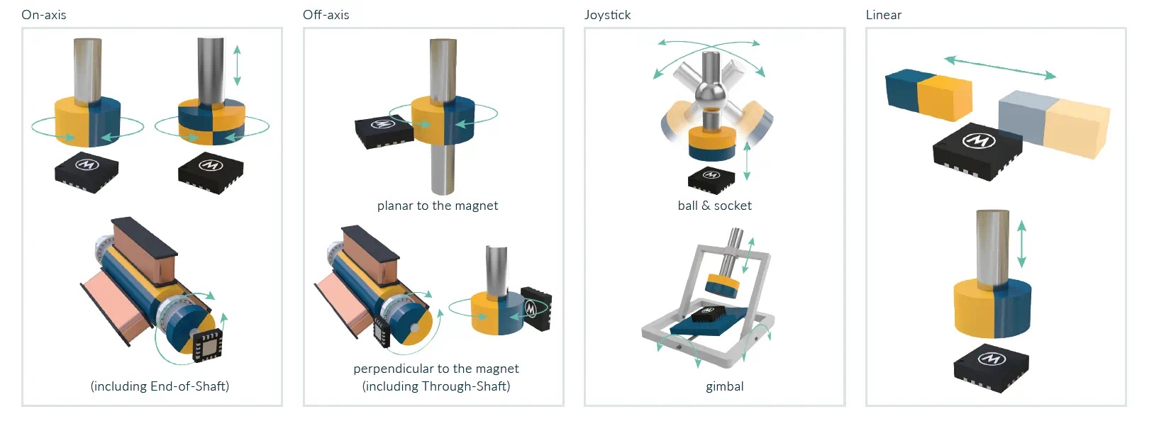
They also have a diagram that kinda shows how the Magnetic Fields affect the sensor array inside the chip package.
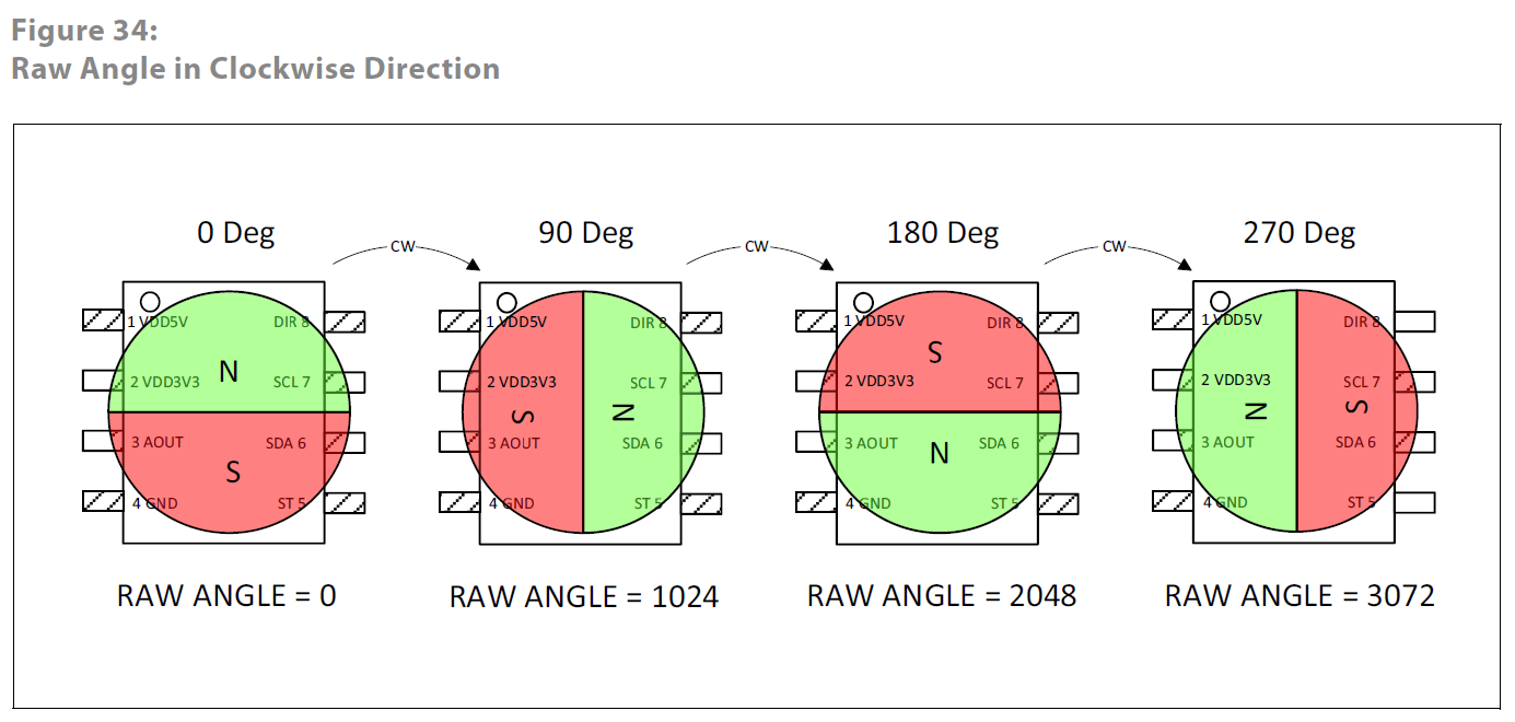
AMS briefly mentions how the angle is calculated from the sensor array readings on a .pdf about picking magnets:
This is an overview of how the magnet’s position translates to the raw 12bit decimal value.
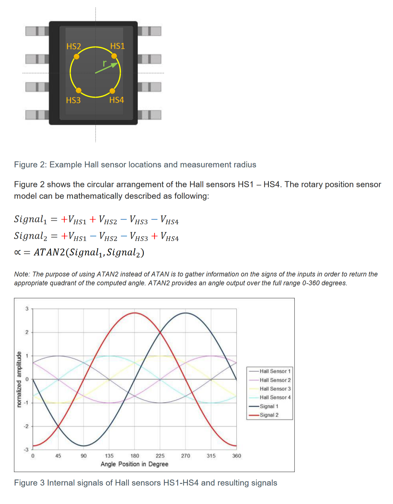
I did find a study that goes into a bit more detail on Magnetic Rotary Encoders:
It mentions how the position is calculated on an 8 sensor array:
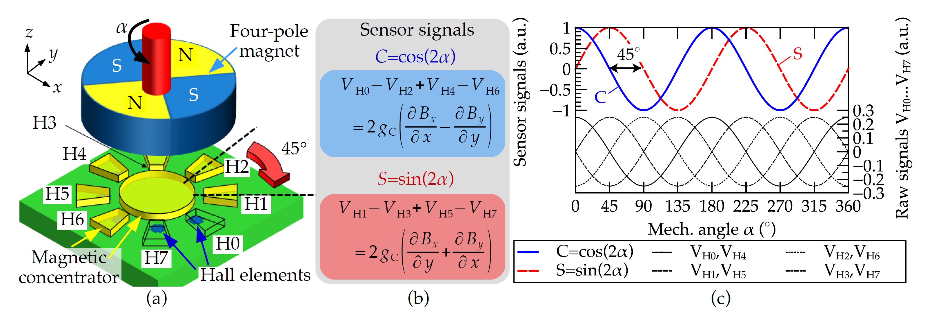
The study shows a microscopic image of an 8 sensor array die. Couldn’t find which model it is.
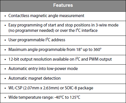
Anyway, I picked the 5600L because it has I2C output, programable addresses so I can have more than 1 on the same BUS:
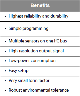
And a very respectable precision of 12bits. Even if there’s going to be noise it can be averaged out somewhat:
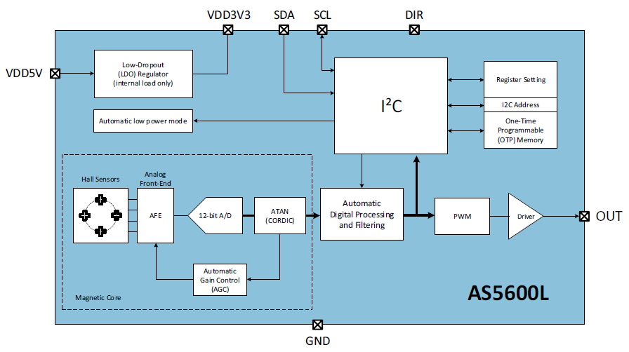
Block Diagram:
Suggestions for magnet size:
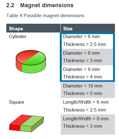
As well as distance to sensors in relation to strength (and shape):
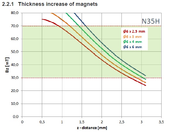
I bought 6mm x 3mm magnets. Diametric magnets are surprisingly hard to find. Didn’t find any other store selling them cheap. Even when I was looking for Magnetic Film Viewing Film.
I2C
The Wikipedia discription of I2C is good enough:
I2C (Inter-Integrated Circuit), alternatively known as I2C or IIC, is a synchronous, multi-master/multi-slave (controller/target), packet switched, single-ended, serial communication bus invented in 1982 by Philips Semiconductors. It is widely used for attaching lower-speed peripheral ICs to processors and microcontrollers in short-distance, intra-board communication.
The SDA and SCL lines each need a pull-up resistor. SCL handles timming and SDA default is logic 1 so devices pull the line low for logic 0.
The basics are Master device first sends an address byte to let the BUS know who it want’s to talk to. A device with that address should aknowledge it “heard the call” and the master will send more bytes detailing if it’s a read/write and what exatly it’s reading/write, etc. The device will then process the request and do it’s thing. In the case of an I2C sensors like the AS5600L the replies are almost always the contents of the registers that store sensor status and angle/magnet position.
This is the oficial hardware Arduino Wire Library made to use an MCU’s I2C pins.
There are also other I2C libraries. Some are hardware alternatives to the Arduino Wire Library, others use software to bypass the I2C peripheral on an MCU. This means you can use I2C in controllers that don’t have hardware support and create I2C BUSes with almost any GPIO. I list some of these in the Input Assignment - Part II page I made to compile 2023’s debugging and research to unclutter this page. MKDocs doesn’t allow relative links to titles but it’s easy to find.
Inside my Networking Assignment I also talk about Bit Banging protocols in general and I2C in particular a bit.
There are plenty of youtube videos about I2C, here are some good ones:
Before moving onto designing a board I did a bit of research on I2C wiring/cabling and there doesn’t seem to be any specific order required.
There are 2x “standards” called Sparkfun QWIIC and Adafruit STEMMA that seem to standout but in general it’s kind of a mess. The only positive is those 2 have the same compatible pinouts but the voltages they operate are not guaranteed to be.
I ended up doing my thing just by what was the easiest to route based on the Mega328p at first and then just went along with it since I already had made the cables.
5V Daughter Boards
Since the sensor I wanted wasn’t included in generally available libraries like the FabLibrary I had to figure something out.
Looked around online but search engines couldn’t find a complete component with both schematic symbol and pcb footprint.
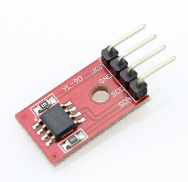
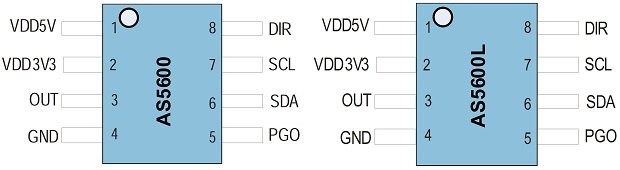
Eventually I noticed both AS5600 and AS5600L had the same pinout.
And the AS5600 was readily available.
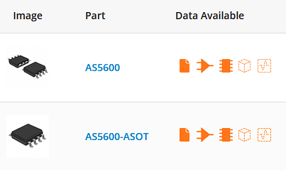
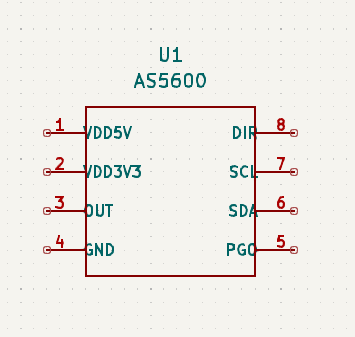
With a symbol and the corresponding footprint.
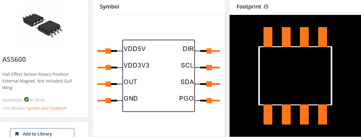
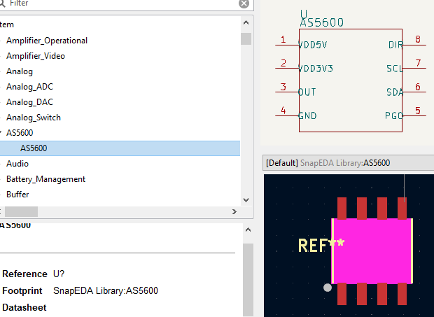
If you want to use the same component I got it from SnapEDA so follow their install instructons here.
They also have a nice little desktop app that can make importing components from their library quite easy.
And that was the hard part.
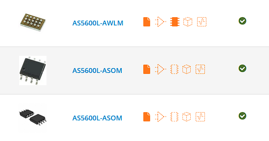
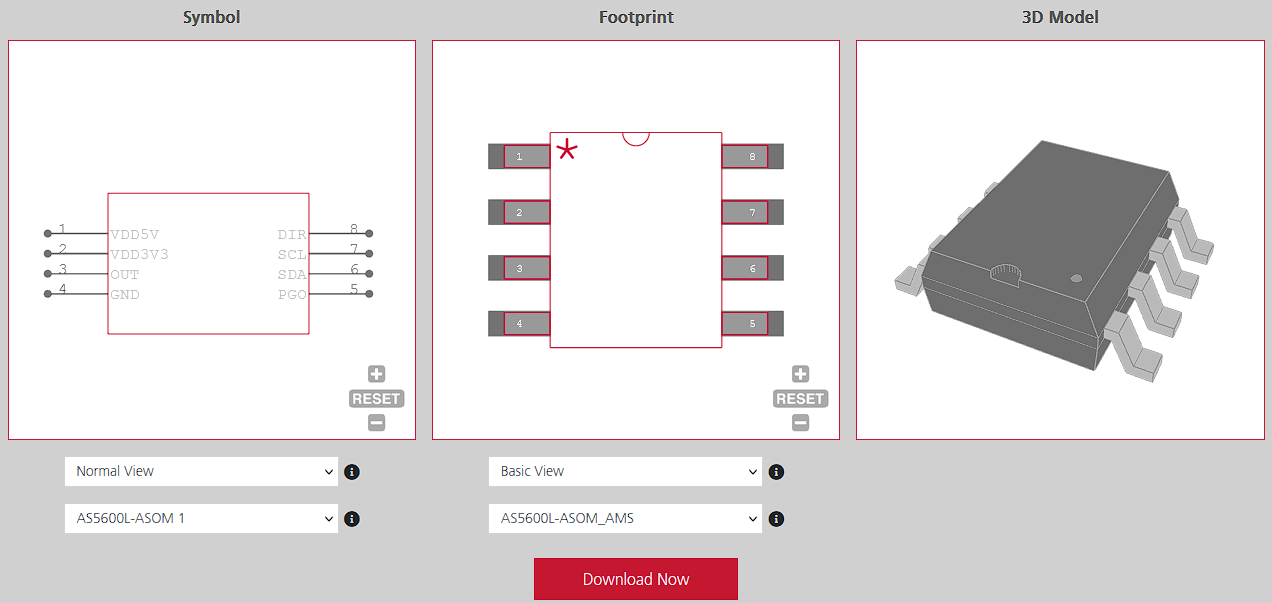
Sometime after I also found the AS5600L in UltraLibrarian.
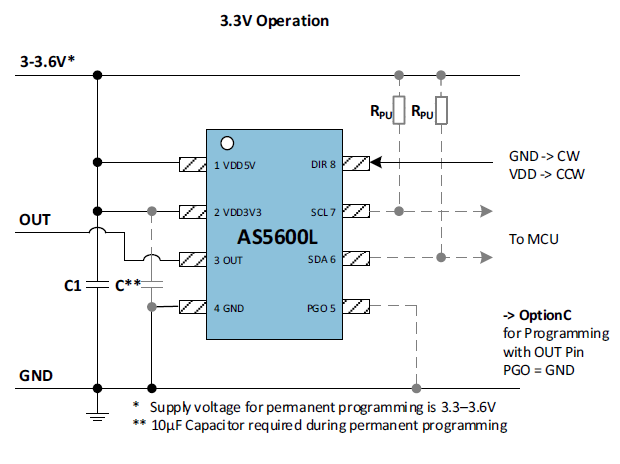
Datasheet time! We need to know how to connect the thing.
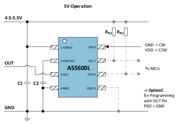
What every pin does.
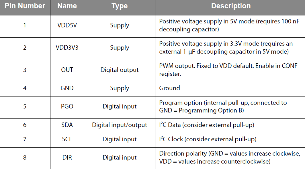
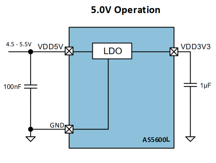
And all the power requirements and recommendations.
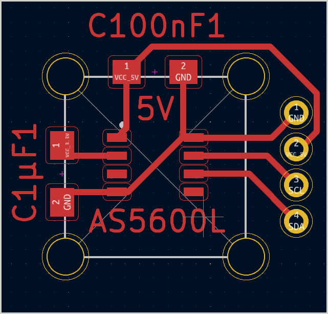
Throw everything into the schematics.
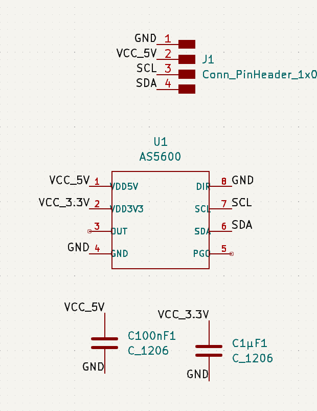
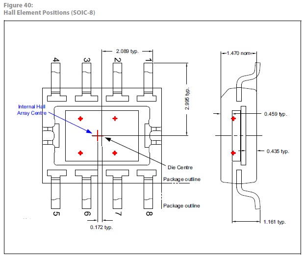
In this case when placing the sensor in the PCB we need to be aware of the magnetic array center so we can line the axis correctly.
Perfecto! #ChefsKiss
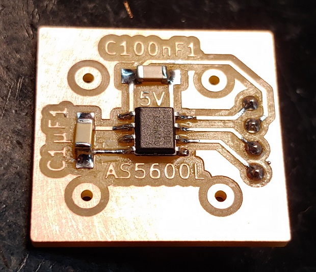
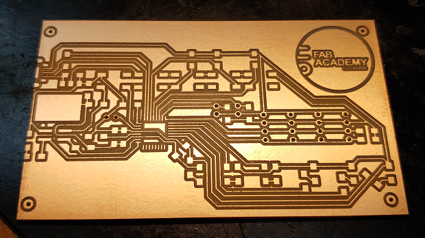
Final Product:
Milled a few boards and came across an unusual problem when I was going to start soldering things on.
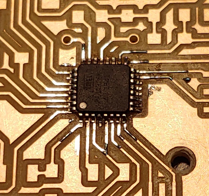
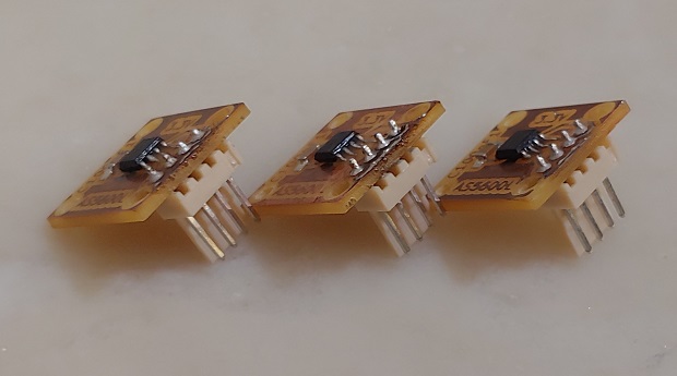
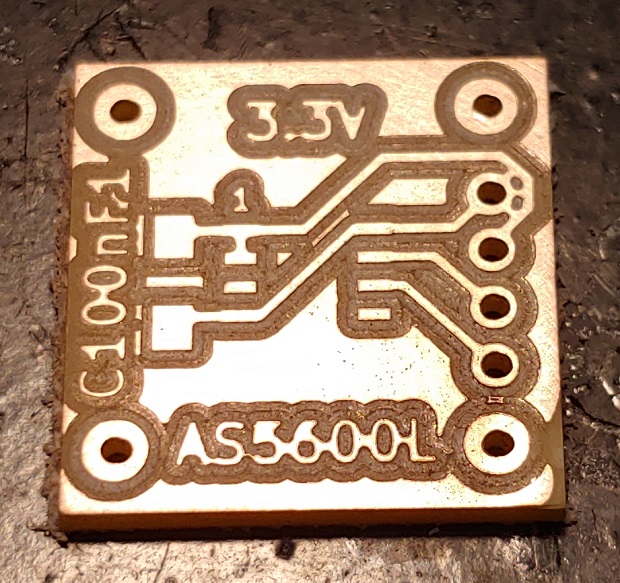
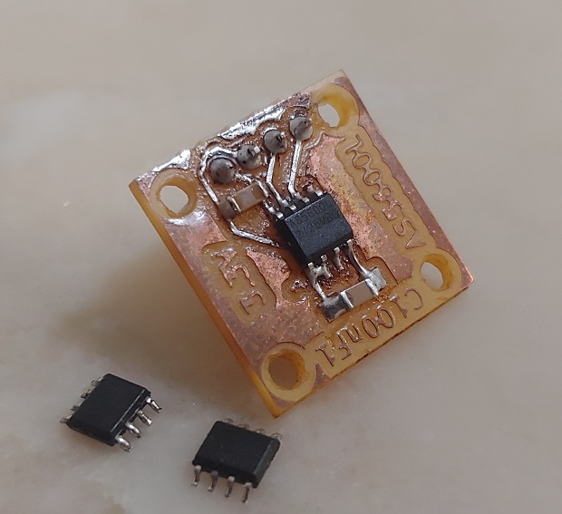
This is what the sensor looks like in the front when your smartphone camera refuses to focus correctly on something so small:
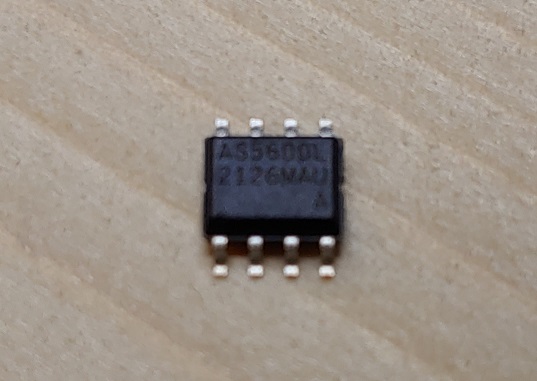
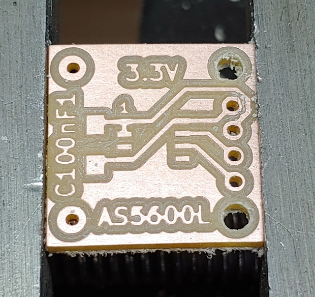
This is what the back looks like:
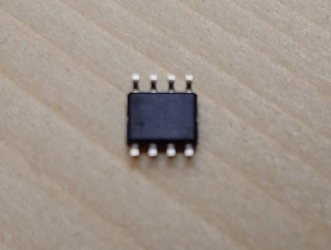
Noticed anything missing? No obvious pin 1 marking…
Research time!
Finding Pin 1
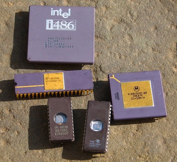
I ended up finding a really nice page on EvilMadScientist with good example pictures.
There are a lot of different ways to highlight Pin 1 in chips.
Big obvious top notch.
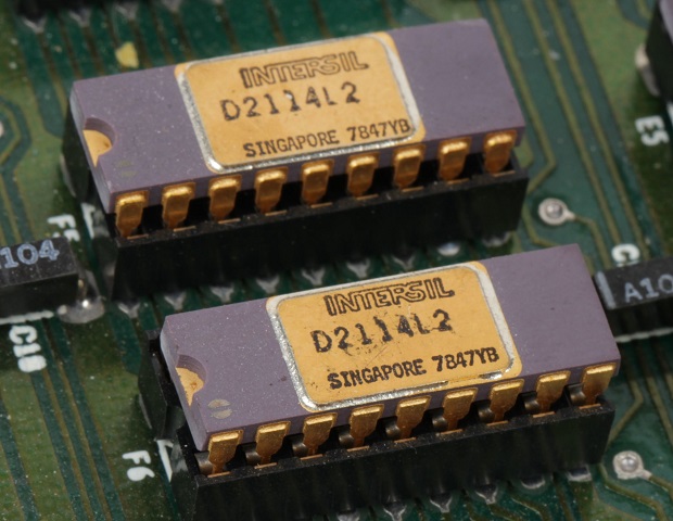
Small corner notch.
Full length side notch.
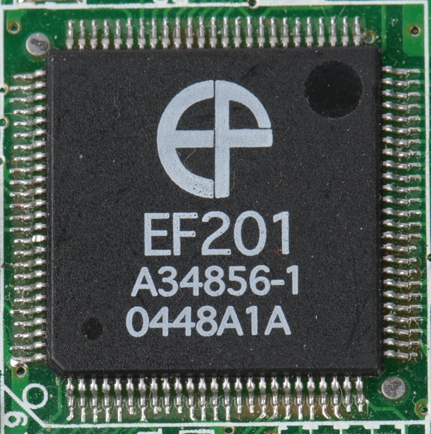
Corner hot-stamp with a pinch of silkscreen.
Laser engraving.
Big golden markings.
Small silkscreen markings.
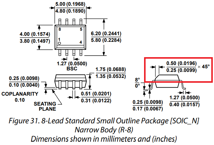
And last but not least side chamfer…
Which reminded me… I’d seen that before… In the datasheet…
Once I was sure I had the correct orintation it was full steam ahead!
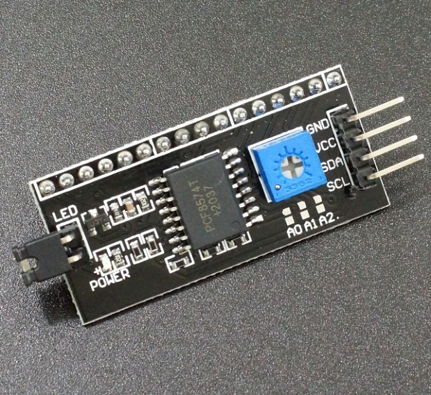
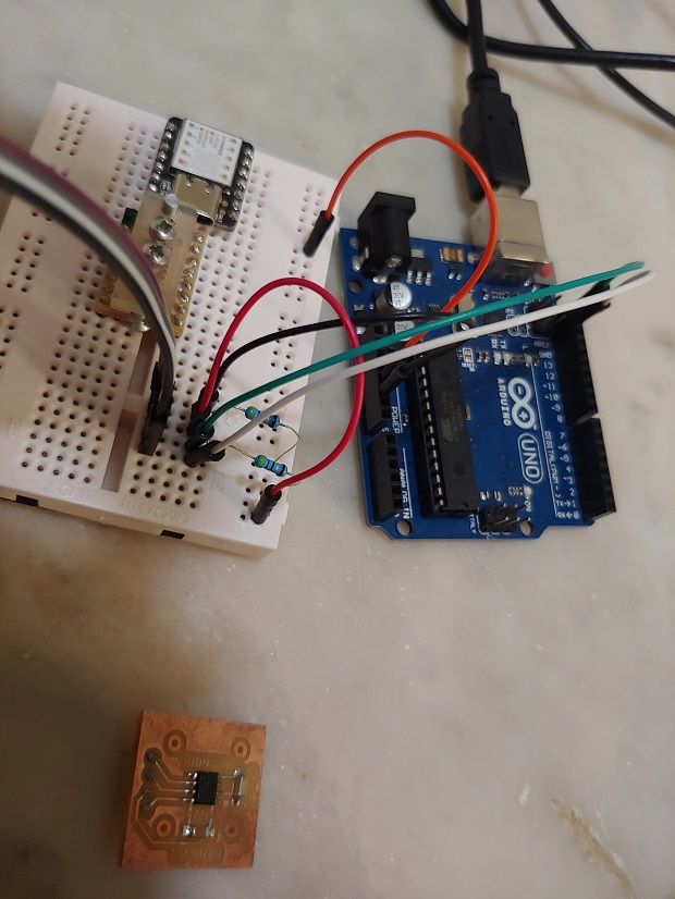
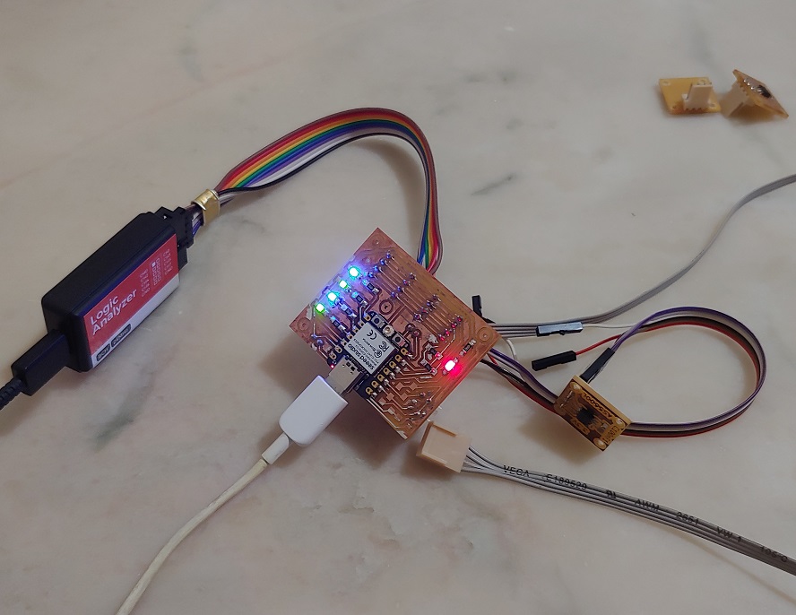
Connecting everthing to the Arduino to make sure they work.
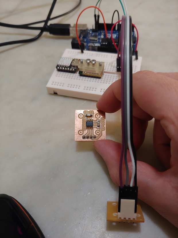
Notice the I2C pull-ups. I think the Arduino Uno has some integrated but we need ower values.
Testing all 3!

They all worked but I compiled all sensor coding stuff to the end of the page.
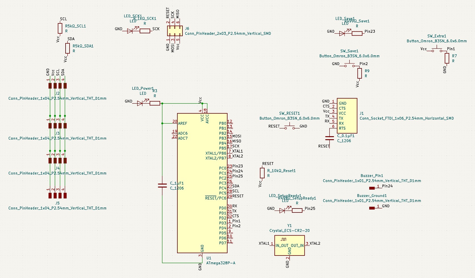
MEGA 328P Motherboard
The only chips we had in stock with more pins than the SOIC-14 Tiny44 were Mega328p and SAMD21. I wasn’t comfortable risking a new architecture so I picked the M328p.
Editor’s note 2023
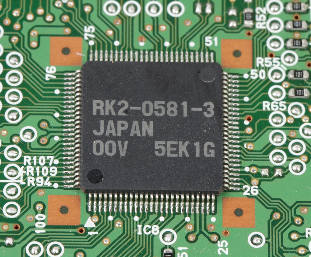
And I hate them so much… Anything with tiny pins like a TQFP package really. They are a nightmare to mill for, especially with the cheap v-bits that are usually stocked in Fab Labs.
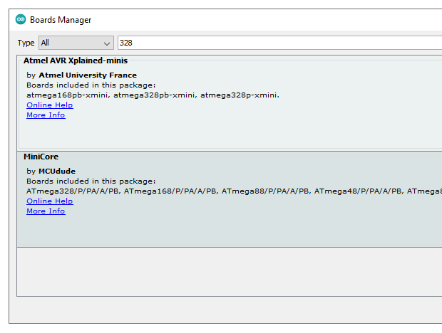
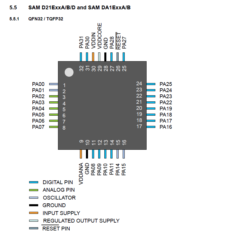
As per usual, download and install the appropriate core.
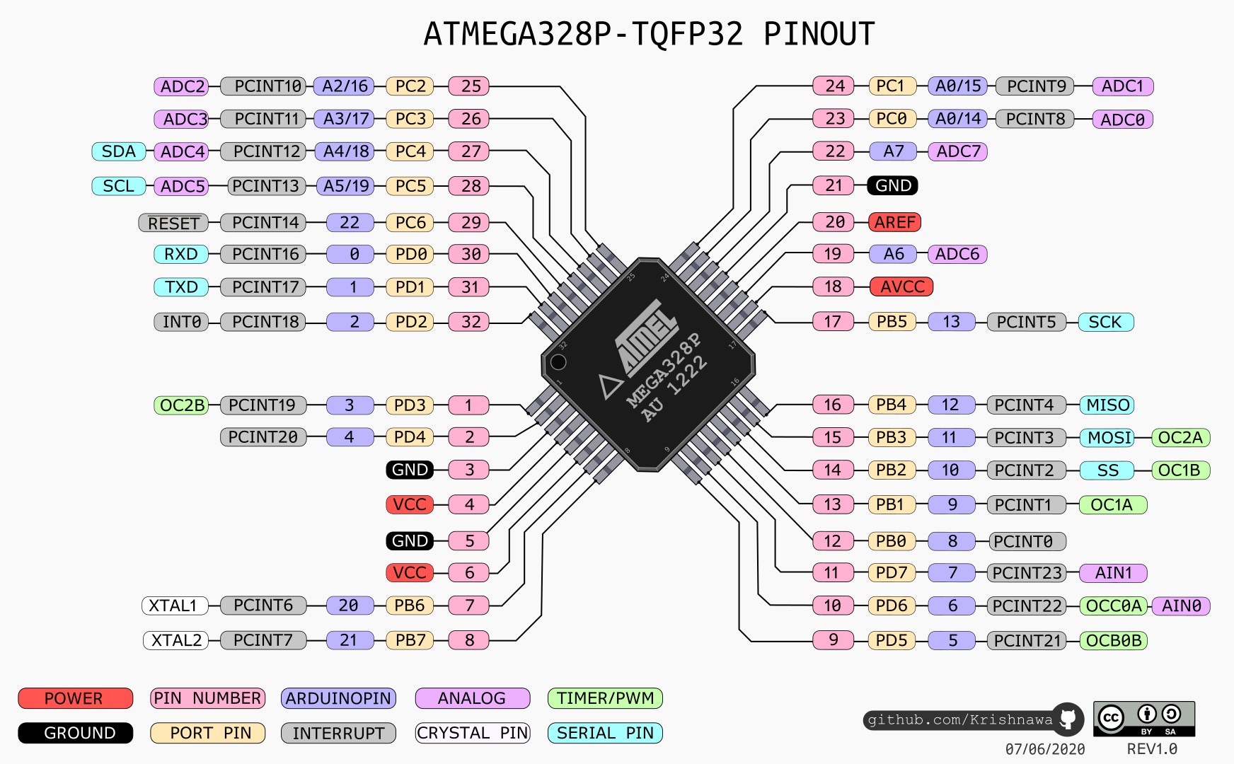
Check the pinout for reference.
Add everything to the schematics and connect away.
Spacing things precisely might come in handy when you’re considering making a box or any type of cover so things like LEDs and buttons line up. Knowing the mouting hole coordinates will help when modeling supports.
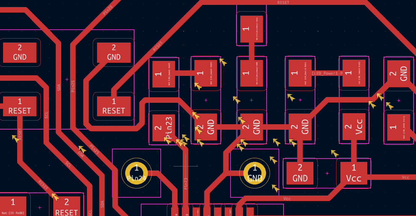
Run a Design Rule Check. When prototyping it’s not as important since a lot of the warnings/errors are things placed over silkscreen, etc. It can be nice to find invisible traces on top of traces that you didn’t delete, etc.
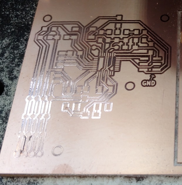
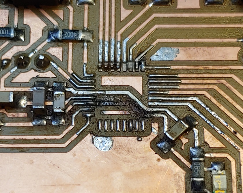
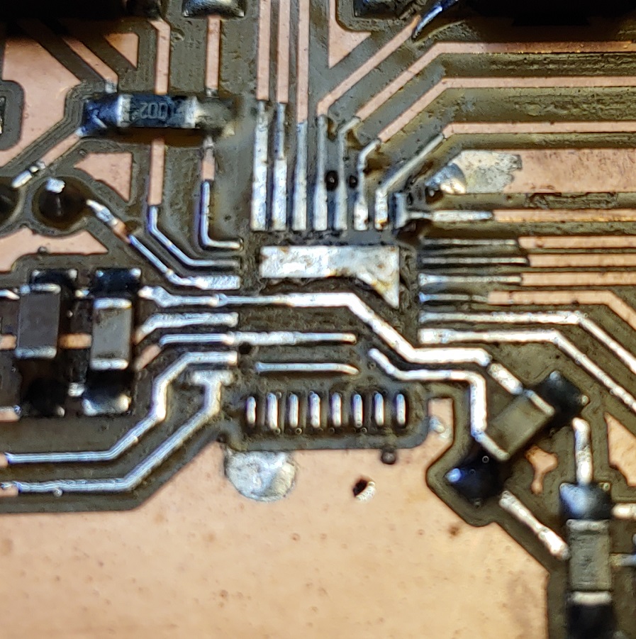
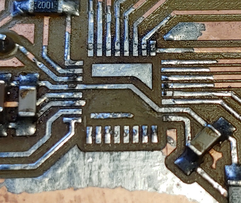
And here’s the problem of trying to mill TQFP packages and anything that has tiny pins spaced tightly… V-bits have a given width for a given depth of cut.
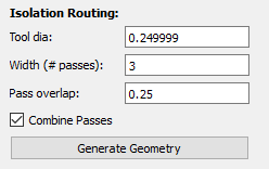
But we’re limited at how wide we can say our tool is or it won’t isolate the tiny pads for the tiny pins.
This means we have to be conservative with depth of cut. If the difference between what the CAM software assumes is the tool cutting width and it’s actual cutting width will is too big it will remove too much copper from the traces.
Cut too shallow and the bit won’t puncture the copper.
Editor’s note 2023
This might also have to do with machine rigidity but I couldn’t test for this at the time.
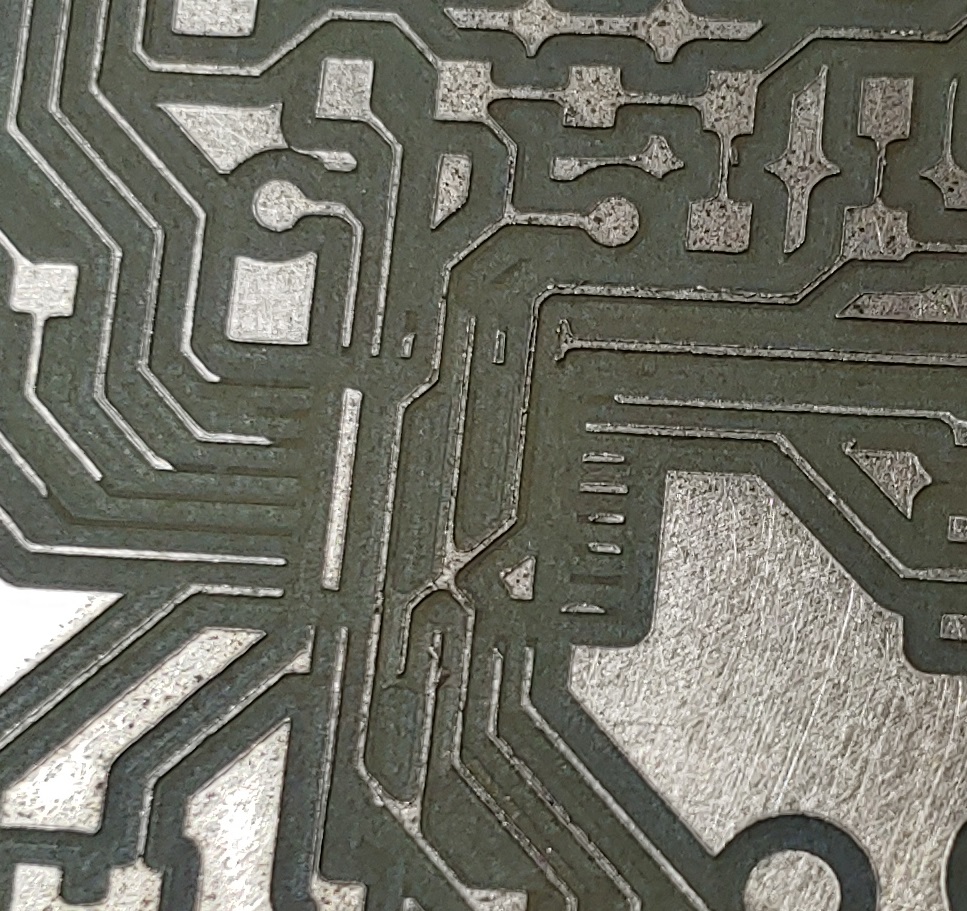
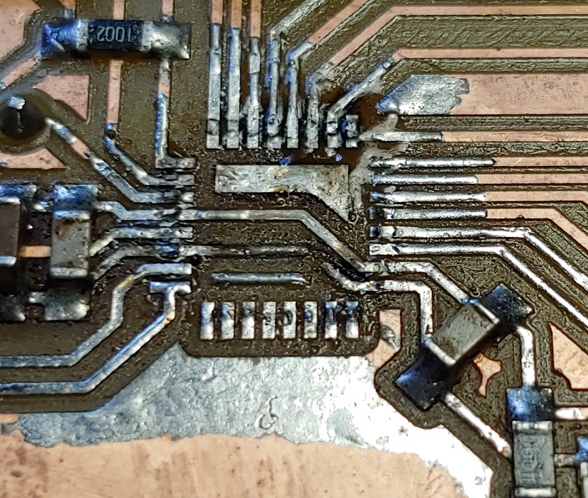
Or cut too deep and the traces become so thin they almost dissapear. This will make them easy to delaminate and get ripped off. Probably cause some funky electronic shenanigans we don’t want to deal with too.
If v-bits are dull/the feed-rate is too low the copper can also smoosh around the perimeter of the cut instead of being removed.
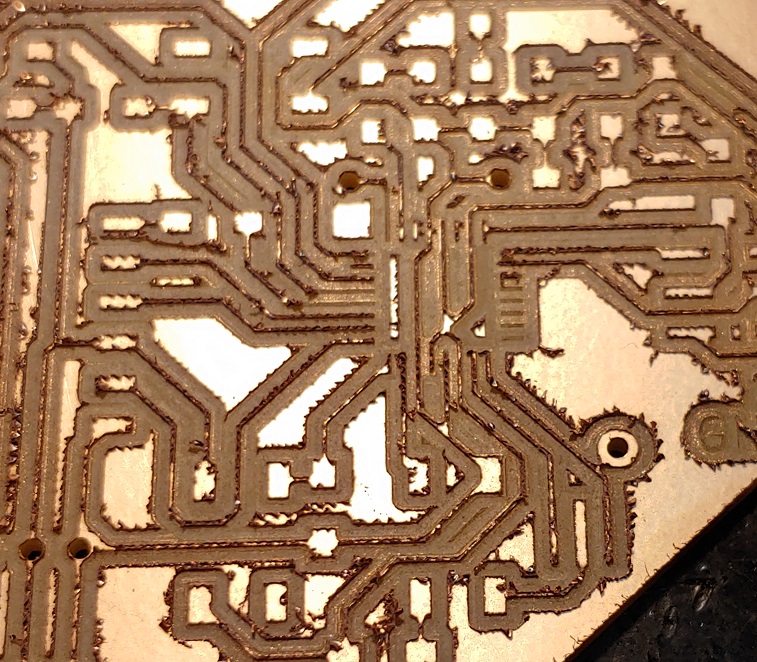
It’s already obvious in the previous picture but after deburing you can see a lot of the traces and pads were ripped off.
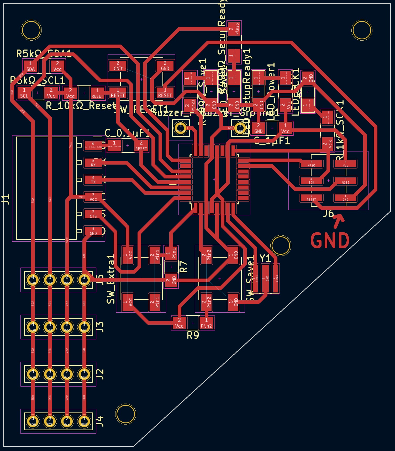
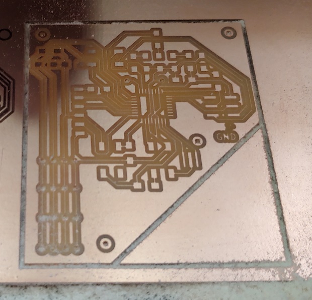
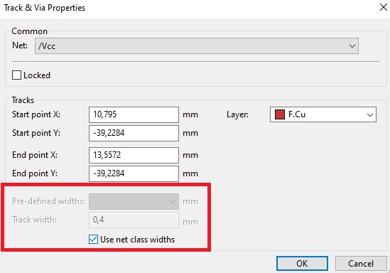
After this last attempt I decided to make all traces as thick as the pads using Net Class. It made updating all traces easier without having to delete and re-do them.
Holding the Mega328p was fun. If it wasn’t for tweezers with a claw like tip I’d probably still be at the Fab Lab trying to hand solder it.
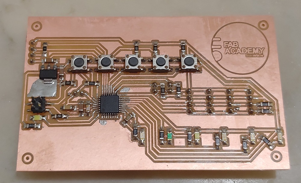
Slightly croocked but it’ll do. Stuffing the rest was easy.
Adding some headers in the back. I love me some 1 way headers. Smother them in super/hot glue.
It Lives!
Shhh, don’t tell anyone but I screwed up the RX and TX pin order for the SPI connection.
Editor’s note 2023
I was too stressed about final presentation dates being around the corner and my electronics being no where near ready that I failed to document how this 328p blinked fine but I never got I2C to work. After all the time I spent on the M328p boards I was focused on trying to figure out a whole new architecture and making a functioning board in just a couple of days.
Funny enough in 2023 when I was looking at the I2C BUS through a Logic Analyzer for a new motherboard:
I noticed something fishy…
Whenever I plugged in a sensor the SDA line would be pulled to ground… Any of my daughter boards… That was hella weird but eventually I figured it out.
So, lol I’m an idiot. The 1st header I soldered on my motherboard I soldered on wrong, flipped 180°… And then I kept copying the same error over and over. Which means this board probably works fine and I could have graduated last cycle. Ah well… Such is life. Got 2 FabAcademies for the price of 1 xD
The daughter boards worked fine on the Arduino because I always had to make sure I was connecting the wires right.
I fixed the headers on the daughter boards since It’d be less work.
My debugging adventures in 2023 were long and arduous so I moved most of them to another page: Input Assignment - Part II.
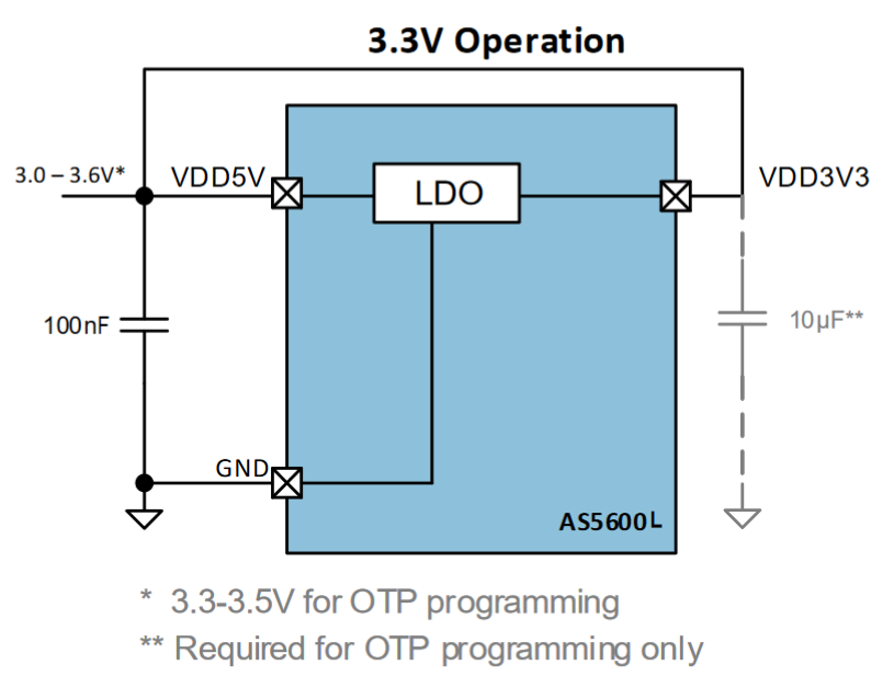
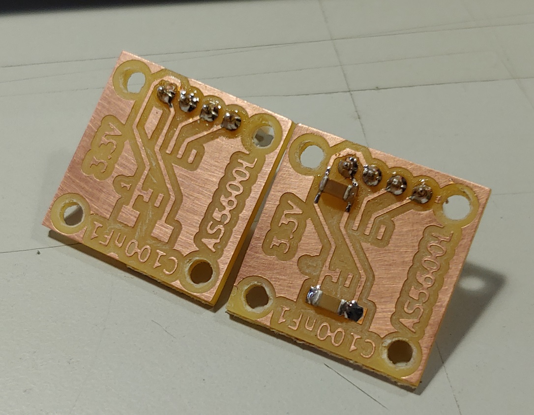
3.3V Daughters
No M328p board means moving to a SAMD21, which means 3.3V logic so I had to re-work the daughter boards. (Also tried re-using a sensor and broken a pin, not worth trying that again. I had a few more sensors.)
Kind of the same but only 1 decoupling capacitor except for programming.
Didn’t notice FlatCAM left me a short.
Had to clear that up on all boards. I also don’t do a tool-change for the larger mouting holes. I just use the through-hole/perimeter end-mill to center them and finish them off with a regular drill if I really need them.
I kinda forgot about the programming capacitor but was lucky that the traces were spaced just perfectly. I could solder it on and remove it easily.
SAMD21E Motherboard
Out with the M328p and in with the SAMD21E18.
Go get the SAM Core. Shout out to Quentin. He’s the core maintainer and provided some help as I debuged my SAMD21 boards. #SpoilerAlert - Couldn’t figure it out before my presentation, but it gave me enough hope that I ended up presenting with what I had… It was enough to get approved and not have to present again. :D
SAM chips are very powerful, a couple times over the Mega328p but one of it’s best features is being able to assign the hardware peripherals to almost any pin we want. Tiny problem when you’re trying to find a regular pinout with functionality set.
Thankfully someone already made a tutorial about it. What matters is what the Core says. Although you can just straight up edit the Core once you know what you’re doing if you want something different. If I’m not mistaken this is the file that handles PIN->Function assignment.
There’s also a more complex power delivery system that needs to be included.
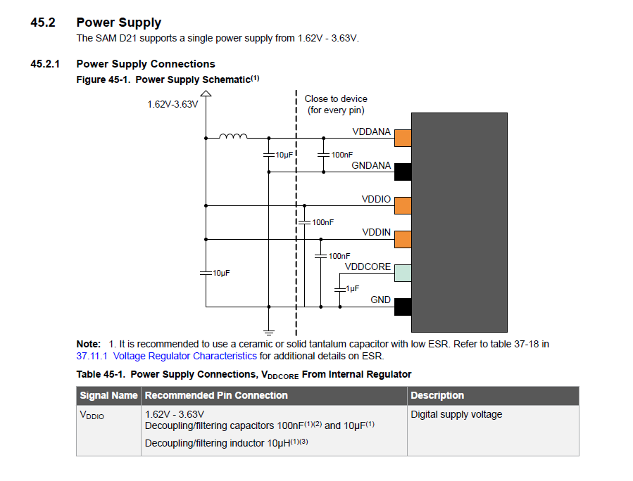
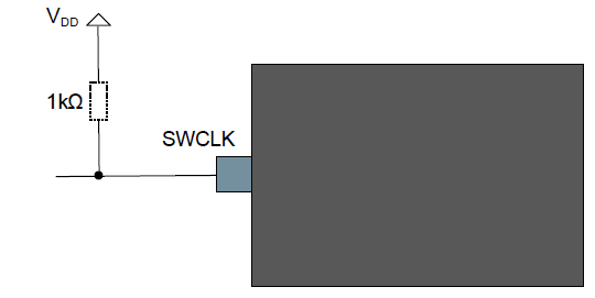
As well as a 1kΩ pull-up on the SWCLK SWD line.
You can also take a look at both Quentin’s example DevBoard and Adrian’s Samdino.
This time I wanted to flair up my board a bit and have a couple more seconds of video for my final presentation video so I decided to add the FabAcademy logo to my board. If you navigate the FabAcademy.org website, at the bottom of the Content menu lies the Marketing page. Entities usually have a page somewhere in their website with some assets for fans/media to use.
In 2023 it points to the 2023 folder that doesn’t have .svg files.
But last year it pointed to the 2022 folder that still has the orignal .svg files I used.
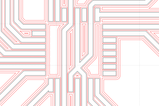
I had to open the logo in Inkscape and edit it since it was full of solid shapes and FlatCAM didn’t like that.

Clean it up.

There we go.

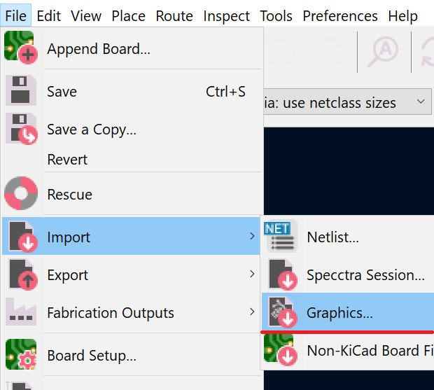
Import graphics.
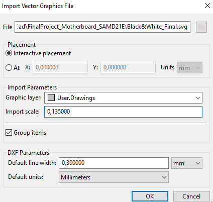
Pick a layer and play around with the scaling to get things into relative proportion.
Since different layers meant different CAM jobs I just edited the files and copy pasted one into another.
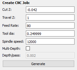
Careful with commands at the begining and end of a file like for example M03 and M05. Those turn the spindle on and off and I broke an end-mill because I failed to delete the end M05 in a receiving file before pasting the extra code. The CNC started the extra code with the spindle stopped.
Looks great. Shame it never worked lol
Also figured out a new technique to grab on to those slippery things.
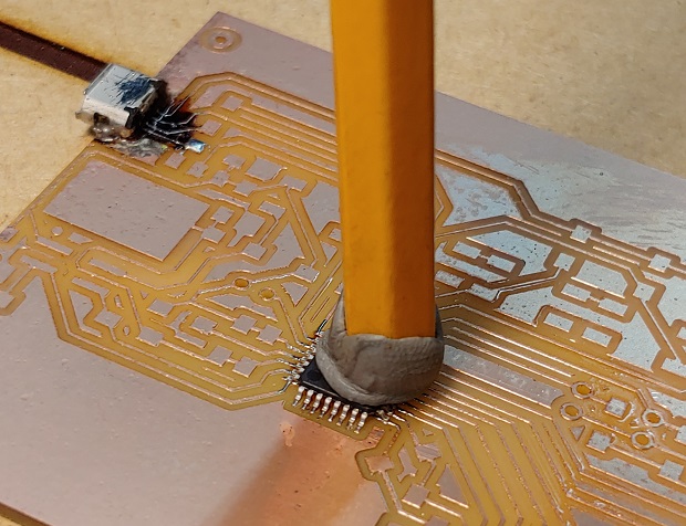
Things were off to a good start when I was just checking if I soldered the LEDs the correct way with an external power supply.
This thing broke right off. Super glue couldn’t care less. Through holes connectors’ where it’s at.
Oh I should also mention, be careful with USB connectors… They’re always moving pins around since some headers are flipped up side down. If you don’t have a datasheet for the USB connector make sure the pins are in the order you design for. Worst case scenario look at the cable plug and go from there:
Editor’s Note
The original .svg from Wikipedia failed to render inside MKDocs, even as pure html code. The other .svg on this page, the I2C diagram, loaded fine. The style element and the text contents were rendering individually so I reworked the CSS classes into the svg components. As I forgot to update the .md file with the new code before pushing it I have a git commit about the svg by itself but it’s not 100% right yet. width="620" height="760" set the relative size of the .svg in the page but viewBox="0 0 250 275" is the original svg viewport. Don’t mess with that property.
Instructor suggested just #YOLOing 4 headers on and using a random adapted usb-cable. So I did.
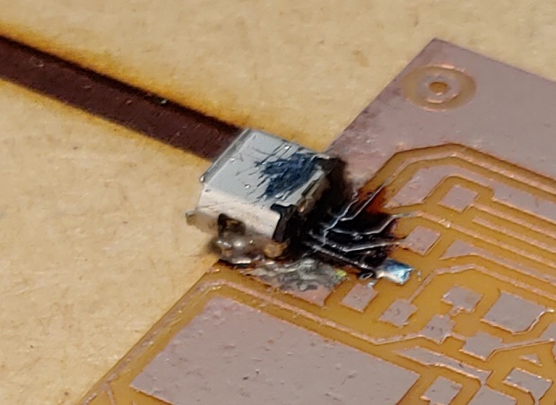
As I connected power to program some sparks flew off… Think I have a short.
Definitely have a short…
Looks worse in focus.
Will it work?
Presentation day came and went while I never toucheed another SAM chip again. Bit of a trauma? Maybe. I also asked Prof. Neil before buying a handful of chips for myself if they were still worth getting and he said not really. Cheap AtTiny’s are still cheap and for more powerful chips an RP2040 or ESP32-C3 are so much better with so much more functionalitly for about the same price that almost made most SAM MCUs obsolete.
As I ran out of time and none of my boards were ready I didn’t get to the part of loading a bootloader with EDBG but I’ll leave some resources I compiled on the subject.
First watch this clip from the 2022 Instructor’s Bootcamp in Aalto. Quentin goes over a lot of details about using SAM boards.
Once you’re ready to install the bootloader follow this tutorial and then this one.
Marius, another student at FCT, documented himself making a Fab SWD Programmer that uses a SAMD11C so it’s the same toolchain.
2023 - ESP32C3 Motherboard
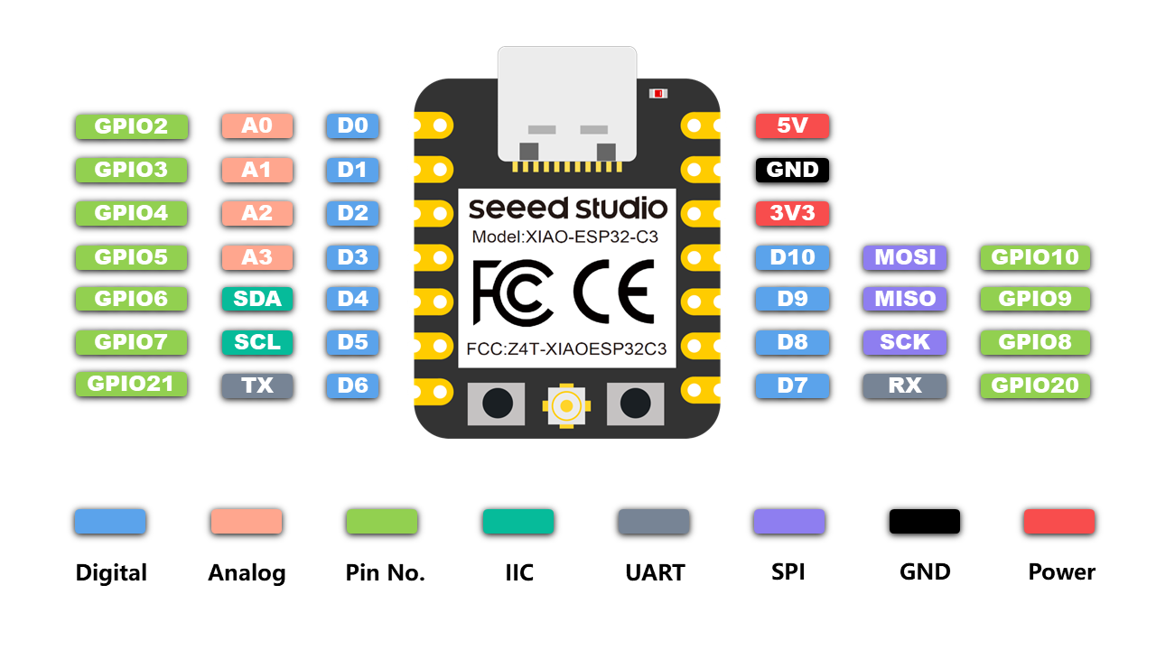
2023 brought quite a few changes to the Electronics curriculum. Namely the change in states from controller modules like the XIAO ESP32-C3 from allowed to recommended. Honestly I didn’t even know they were allowed last year or I’d’ve bought some..... Castellated pins are ok to use.
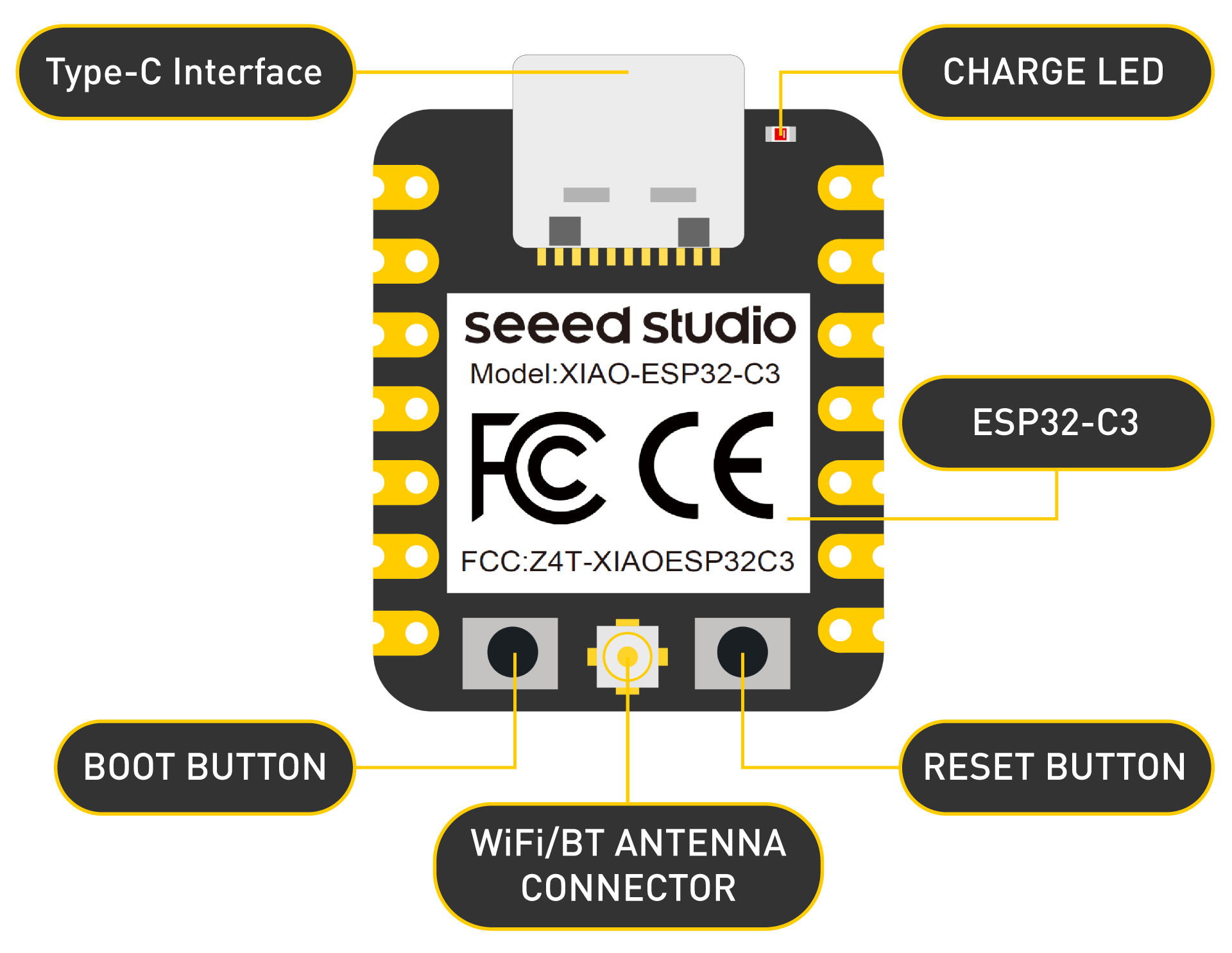
I already went over the specs general specs of an ESP32-C3 chip in Embedded Programming but these are the XIAO module’s:
- Powerful CPU: ESP32-C3, 32bit RISC-V singlecore processor that operates at up to 160 MHz
- Complete WiFi subsystem: Complies with IEEE 802.11b/g/n protocol and supports Station mode, SoftAP mode, SoftAP + Station mode, and promiscuous mode
- Bluetooth LE subsystem: Supports features of Bluetooth 5 and Bluetooth mesh
- Ultra-Low Power: Deep sleep power consumption is about 43μA
- Better RF performance: External RF antenna included
- Battery charging chip: Supports lithium battery charge and discharge management
- Rich on-chip resources: 400KB of SRAM, and 4MB of on-board flash memory
- Ultra small size: As small as a thumb(20x17.5mm) XIAO series classic form-factor for wearable devices and small projects
- Reliable security features: Cryptographic hardware accelerators that support AES-128/256, Hash, RSA, HMAC, digital signature and secure boot
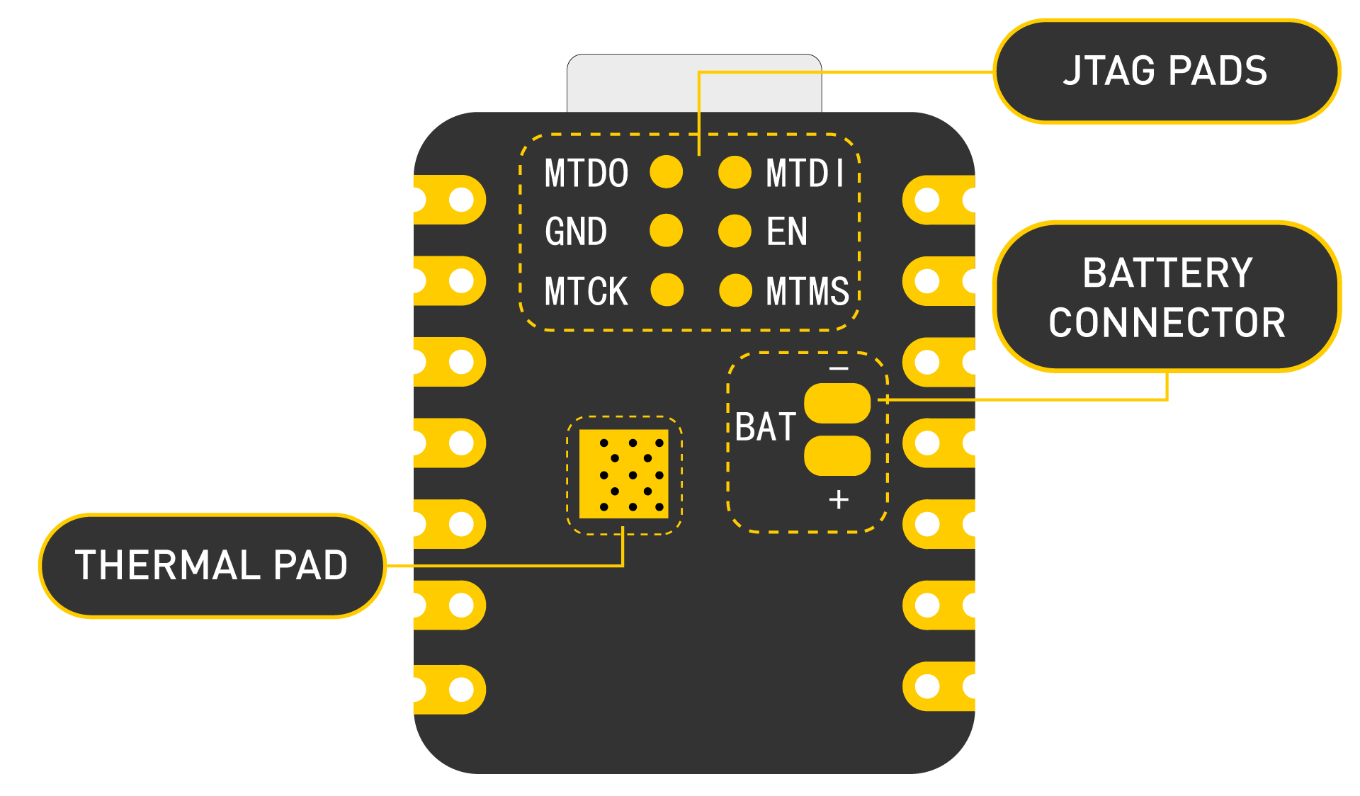
- Rich interfaces: 1xI2C, 1xSPI, 2xUART, 11xGPIO(PWM), 4xADC, 1xJTAG bonding pad interface
- Single-sided components, surface mounting design
The only thing missing would really be an integrated LED for educational purposes.
I tried designing my pcb in a way that I could add a battery in the future but FR1 and reflow don’t go well together. More on that later.
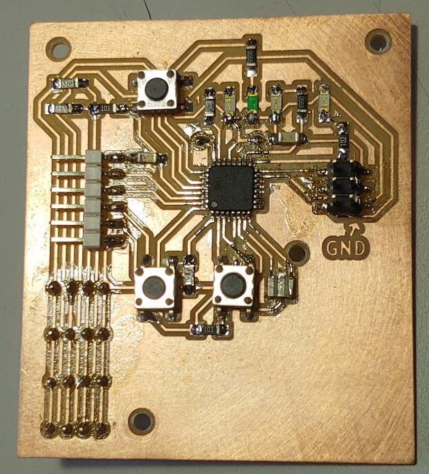
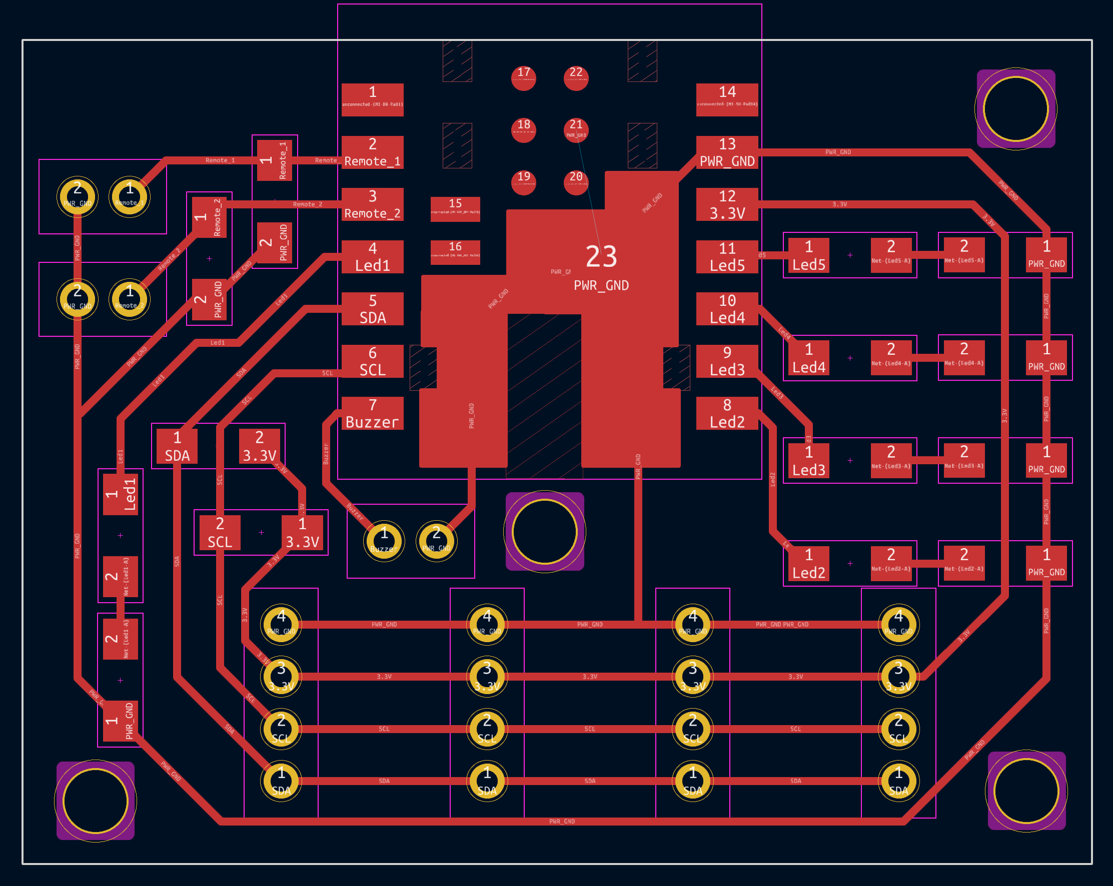
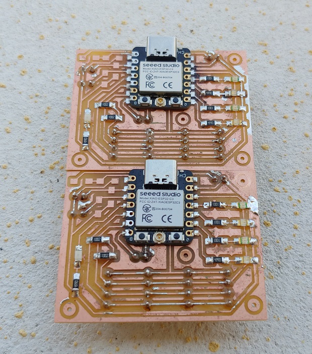
These are all the components I need for 2 wired buttons, some I2C 4pin headers and 5 LEDs I actually screwed that up because my button resistors should be pull-ups but I connected everything to ground. I’ll have to figure something out. No idea how I missed that before milling…
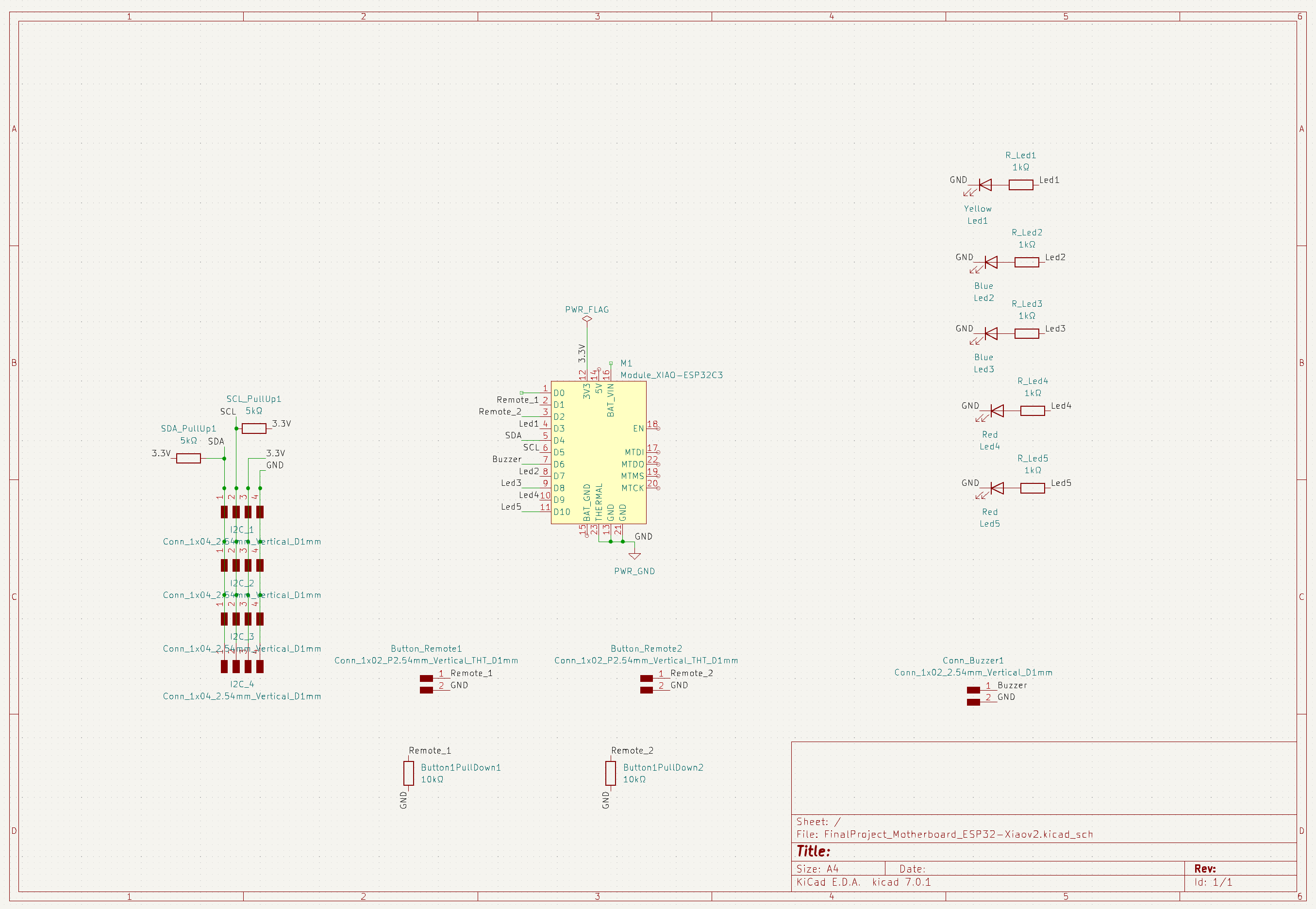
Bit more work than I expected. There used to be a voltage divider on the top left to try and check battery charge in the future but I removed those components.
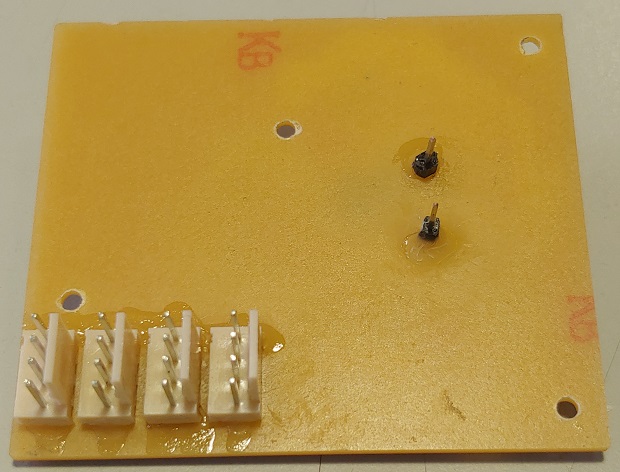
Made 2 just in case.
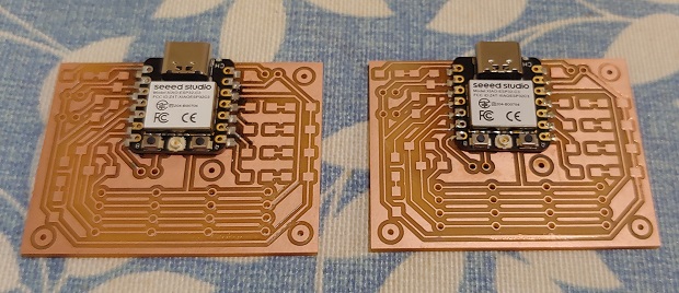
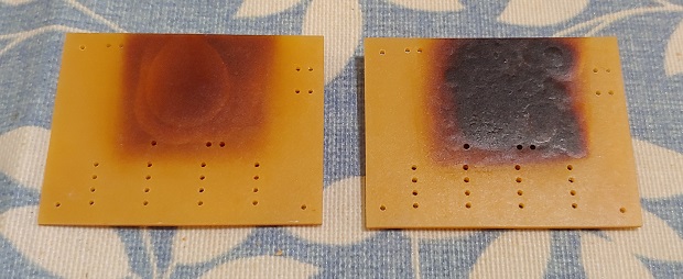
Originally I wanted to try reflow to use the battery pins at the bottom of the module but FR1 disliked it.
I tried a bit more and patched things up with a regular iron just in case.
I had to remove them anyway because both boards had hidden shorts under the modules.
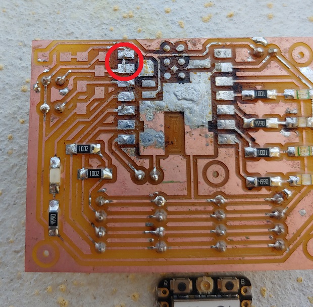
In any case I used a Miniware MHP30 Mini Hot Plate.
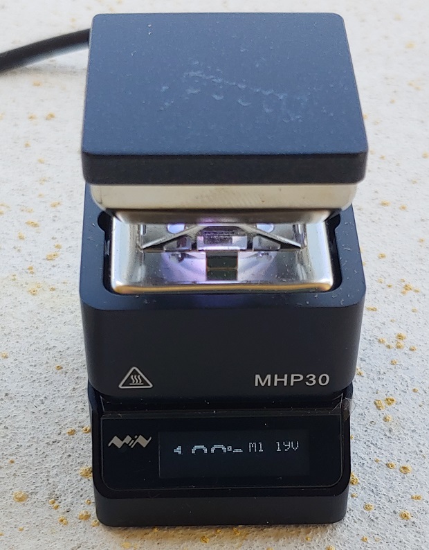
It’s a bit small so it can become a game of balancing larger boards on it but it gets the job done. Basic specs:
- Heating area: 30mm*30mm
- Temperature range: 100-350°C (300 software limited)
- Power: 60W
- Power input: USB-C PD
- Size: Controller (LxWxH): 42mm x 35mm x 52mm
There’s also a version of IronOS that’s compatible. This MHP30 isn’t mine so I haven’t tested it. (TS100 version is awesome.)
All done:
Loading up a quick blink test:
Debugging My ESP32 Boards
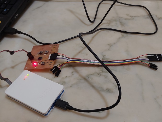
And this is when things go sideways again. I2C wasn’t working.
Like I mentioned on the Editor’s Note at the end of my Mega328P documentation I hooked the boards to a cheap Logic Analyzer to see what was up.
Something was causing the SDA to go low as soon as I plugged any daughter board.
Eventually I figured out I had been soldering my headers on my motherboards wrong. I flipped the 1st one 180° in relation to the daughter boards/cables and copied that incorrect orientation over and over again. As fixing the motherboards was more work I just re-soldered the headers on the daughter boards.
Things were very unstable so just in case I also replaced some of the sensors that seemed less reliable. Just in case functioning so long with SDA-GND and SCL-VCC flipped fried anything.
Also tried making a fake device to make sure I2C was working to exclude the motherboards.
I used this code I got from ChatGPT:
#include <Wire.h>

// Define the slave address
#define SLAVE_ADDRESS 0x40 // This address will be acknowledged by this device.

// Define a flag to indicate whether the device has received data
volatile bool dataReceived = false;

// Function to handle I2C data reception
void receiveData(int byteCount)
{
  while (Wire.available())
  {
    // Read the received data from the master
    char receivedData = Wire.read();
    // Process the received data as needed
    // Set the dataReceived flag to true
    dataReceived = true;
  }
}
void setup()
{
  // Initialize the I2C communication as a slave device
  Wire.begin(SLAVE_ADDRESS);
  // Set the receive callback function
  Wire.onReceive(receiveData);
  // Start the Serial communication for debugging (optional)
  Serial.begin(9600);
  Serial.println("I2C Slave Device initialized");
  pinMode(LED_BUILTIN, OUTPUT);
}

void loop()
{
  // I thought about setting the LED to blink on each ping but with a regular blink loop I was sure the code was actually running.
  Serial.println("Test");
  digitalWrite(LED_BUILTIN, LOW); //LOW turns LED on in the XIAO
  delay(2000);
  digitalWrite(LED_BUILTIN, HIGH);
  delay(2000);
}
I2C was working as expected.
That’s when I just started desperetly looking for reasons why I2C might be unstable.
I got into such a deep rabbit hole I decided to put most of that research into another page: Input Assignment - ALL the Debugging.
I ended up reading about a lot of concepts and physical properties of materials and electric signals that can affect our boards so they should be taken into account when designing a board from scratch. Especially with faster signals like I2C. Wikipedia says the spec goes up to 5Mbit/s… Original speed is 100Kbit/s but the AS5600L goes up to 1Mbit/s, also known as Fast Mode Plus.
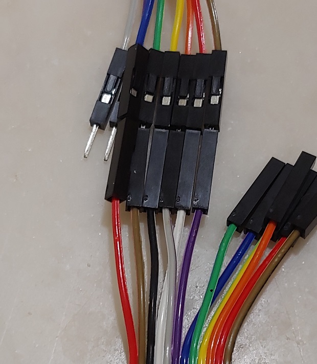
In the end; after making sure the pull-up resistors had the best possible value, were soldered on correctly, a new daisy chain cable for all daughter boards and slowing down the BUS below spec to 50kbit/s it seemed I2C was stable enough. At least for a few minutes. It wasn’t perfect but it should be enough to get a few readings to graduate.
Apparently I2C is very picky and doesn’t like long cables too.
It’s not really an oficial extension of I2C but there’s also something called Differential I2C that has special ASIC intermediary chips to generate 2x differential pairs of both SDA and SCL signals. They can help neutralize noise over much longer distances.
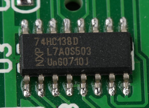
There are comercial modules on sale that can be quickly integrated for testing. That Sparkfun model uses a NXP PCA9615 chip. NXP marketing calls it a Differential I2C-BUS Buffer With Hot-Swap Logic but there are others.
Programing
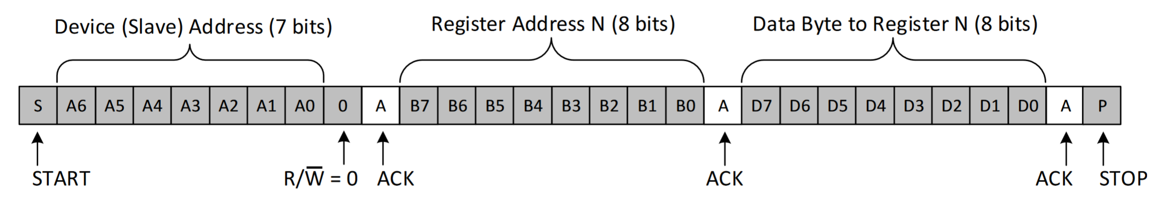
Understanding the role of registers in I2C exchanges is important when a library isn’t available and we have to code everything by hand. After calling out for a device address we often tell that device which register we want to interact with. In the case of the AS5600L it usually starts with device address and read/write + register address to which the device replies with it’s own address back so we know who is replying and the contents of said register. More than one can be called up, which is important since the magnet position is stored in 2 bytes as the resolution is 12bits.
An outgoing request about 2 registers will look like:
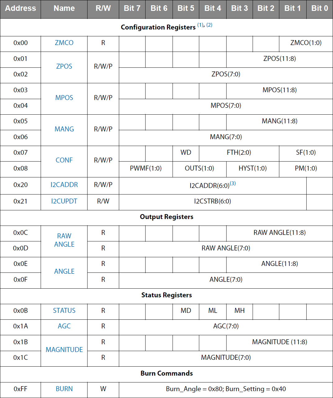
These are all the AS5600L registers:
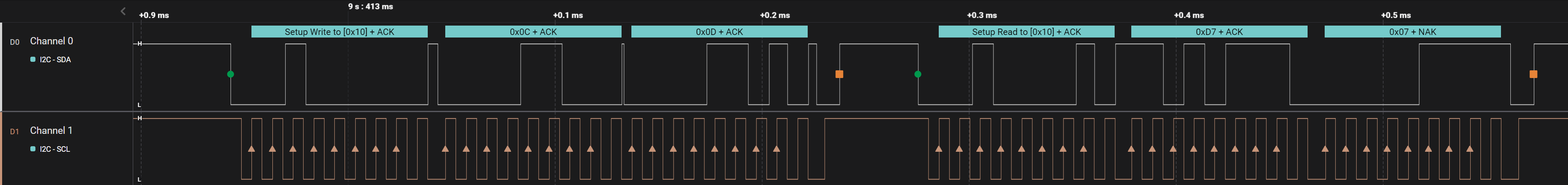
And this is an actual request to an AS5600L (0x10) for both, 0x0C and 0x0D registers, that contain the 12bit raw Angle value and the 2x byte reply.
When you don’t have a library, understanding how to interact with registers is very important. If you want to learn a bit more watch this video:
Before going into detail about the code here’s it working and printing values to the serial monitor:
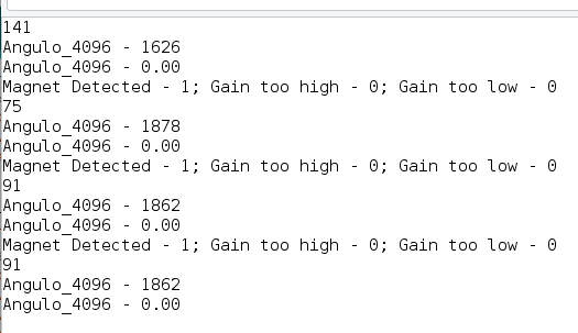
When I took this print-screen I was still working out the kinks of converting the 12bit value into 360 equivalent but the code does so now. Had to force Float math by adding a decimal point or it would fail to solve and return 0.
Read Status Bits and Angle
#include <Wire.h>

byte magnetStatus;
byte gainStatus;
byte MH;
byte ML;
byte MD;
uint16_t temp;
float Angle;

void setup(){

  Wire.begin(); // Wire communication begin
  Serial.begin(9600); // The baudrate of Serial monitor is set in 9600
  while (!Serial); // Waiting for Serial Monitor
  Serial.println("Waiting For Serial");

}

void loop(){

  Wire.beginTransmission(0x40);  // Communicate with device @ deviceAddress!
  Wire.write(0x0B);   // Command byte to target registerAdress (0x0B Status Register)
  Wire.endTransmission();
  Wire.requestFrom(0x40, 1); // send me the data from 1 register, previously called for.
  delay(10);
  magnetStatus = Wire.read();
  MH = bitRead(magnetStatus, 3);
  ML = bitRead(magnetStatus, 4);
  MD = bitRead(magnetStatus, 5);
  Serial.println("Magnet Detected - "+String(MD)+"; Magnet too weak/far away - "+String(ML)+"; Magnet too strong/close - "+String(MH)); // Magnet too far means the gain is too high, magnet too close means gain is too low.
  //delay(500);
  Wire.beginTransmission(0x40);  // Communicate with device @ deviceAddress!
  Wire.write(0x1A);   // Command byte to target registerAdress (0x1A Gain value)
  Wire.endTransmission();
  Wire.requestFrom(0x40, 1); // send me the data from 1 register, previously called for.
  delay(10);
  gainStatus = Wire.read();
  Serial.println("Magnet Distance Gain - "+gainStatus);
  //delay(500);
  Wire.beginTransmission(0x40);  // Communicate with device @ deviceAddress!
  Wire.write(0x0C);
  Wire.write(0x0D);// Both registers must be called for.
  Wire.endTransmission();
  Wire.requestFrom(0x40,2); // send me the data from 2 register, previously called for.
  delay(10);
  byte low = Wire.read();
  byte high = Wire.read();
  temp = word(high,low); // word creation depends on the order the registers were called in
  Serial.println("Angulo_4096 - " + String(temp)); // raw 12 bit data
  Angle = temp * 360.0 / 4096; // .0 forces the float calculation
  Serial.print("Angulo_360 - "); // converstion to 360 degrees
  Serial.println(Angle,4); // Default shows all decimal places so we have to explicitly add a cutoff value
  delay(1500);
}
To pull out an individual bit from a byte I used the [BitRead() function](https://www.arduino.cc/reference/en/language/functions/bits-and-bytes/bitread/.
I can’t remember why I used println() instead of regular print() but both can convert the print message into other number numerical systems or the number of decimal places.
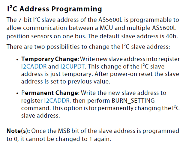
After understanding how to read the registers I moved on to the I2C address registers. Since I needed 3x sensors on the same BUS I had to re-program at least 2x from the default.
Temporary Burn
#include <Wire.h>

byte DeviceAddress = 0x40; // Factory Default Device Address
byte AddressRegistry = 0x20;
byte AddressRegistryTemp = 0x21;
byte NewAddress = 0x10;
byte HighestAddress = 0x20; // 1st bit on the left is 1 by default, register ignores the 1st bit on the right so we'll have to offset everything 1 to the left eating anything we input as the 2nd bit on the left. That leaves 2^5=32.
                            // 1st bit might be burnable as a 0, TBD.

void setup(){
  Wire.begin(); // Wire communication begin
  Serial.begin(9600); // The baudrate of Serial monitor is set in 9600
  while (!Serial); // Waiting for Serial Monitor
  Serial.println("Waiting For Serial");
  if (NewAddress > HighestAddress){
    Serial.println("New Address Must be below " + String(HighestAddress));
  } else {
    //-- Temporary Address
    NewAddress = NewAddress * 2; // multiplying everything by 2 in binary offset the whole number 1 bit to the left. Dividing offsets everything to the right and ignores anything beyond the radix.
    Serial.println(NewAddress);
    Wire.beginTransmission(DeviceAddress);  // Communicate with device @ deviceAddress!
    Wire.write(AddressRegistry);   // Command byte to target I2CADDR
    Wire.write(NewAddress); //
    Wire.endTransmission();
    Wire.beginTransmission(DeviceAddress);  // Communicate with device @ deviceAddress!
    Wire.write(AddressRegistryTemp);   // Command byte to target I2CUPDT
    Wire.write(NewAddress);
    Wire.endTransmission();
    Serial.println("\nAddress temporarily changed");
    //--
  }

  while (!Serial); // Waiting for Serial Monitor
  Serial.println("\nI2C Scanner");
}

void loop()
{
  byte error, address; //variable for error and I2C address
  int nDevices;

  Serial.println("Scanning...");

  nDevices = 0;
  for (address = 1; address < 127; address++ )
  {
    // The i2c_scanner uses the return value of
    // the Write.endTransmisstion to see if
    // a device did acknowledge to the address.
    Wire.beginTransmission(address);
    error = Wire.endTransmission();

    if (error == 0)
    {
      Serial.print("I2C device found at address 0x");
      if (address < 16)
        Serial.print("0");
      Serial.print(address, HEX);
      Serial.println("  !");
      nDevices++;
    }
    else if (error == 4)
    {
      Serial.print("Unknown error at address 0x");
      if (address < 16)
        Serial.print("0");
      Serial.println(address, HEX);
    }
  }
  if (nDevices == 0)
    Serial.println("No I2C devices found\n");
  else
    Serial.println("done\n");

  delay(5000); // wait 5 seconds for the next I2C scan
}
After figuring out how to send data and how the sensor interpreted the data I finally managed to temporarily burn the address I wanted. After some trial and error I figured how to temporarily burn the address I picked. The max addresses isn’t strictly well calculated but it’s not important. If you need to configure an AS5600L with an address outside that 32 range I’m sure you’ll figure it out.
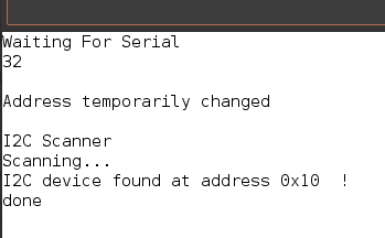
Permanent Burn
Once I understood out how to temp burn the address I wanted I had to then figure out how the perma burn command worked and try not to screw it up. In the end it was very similar; instead of burning the temp address on 2 different registers I wrote the address once and wrote the burn command into the burn register.
#include <Wire.h>

byte DeviceAddress = 0x40; // Factory Default Device Address
byte AddressRegistry = 0x20;
byte NewAddress = 0x20; // Sensor needs to be restarted to apply the new address
byte BurnRegistry = 0xFF;
byte BurnCommand = 0x40;
byte HighestAddress = 0x20; // 1st bit on the left is fixed to 1, register ignores the 1st bit on the right so we'll have to offset everything 1 to the left eating anything we input as the 2nd bit on the left. That leaves 2^5=32.

void setup(){
  Wire.begin(); // Wire communication begin
  Serial.begin(9600); // The baudrate of Serial monitor is set in 9600
  while (!Serial); // Waiting for Serial Monitor
  Serial.println("Waiting For Serial");
  if (NewAddress > HighestAddress){
    Serial.println("New Address Must be below " + String(HighestAddress));
  } else {
    Wire.beginTransmission(DeviceAddress);
    byte AddressError = Wire.endTransmission();
    if (AddressError == 2) // endTransmission() returns a few codes, 2 Means NACK (Not Aknowledged) on Address byte, meaning no plugged-in I2C device recognized the address.
    {
      Serial.println("No I2C device found at Targeted Address!\nCouldn't Complete New Address BURN.");
    } else {
      //-- Temporary Address
      NewAddress = NewAddress * 2; // multiplying everything by 2 in binary offset the whole number 1 bit to the left. Dividing offsets everything to the right and ignores anything beyond the radix.
      Serial.println(NewAddress);
      Wire.beginTransmission(DeviceAddress);  // Communicate with device @ deviceAddress!
      Wire.write(AddressRegistry);   // Command byte to target I2CADDR Registry
      Wire.write(NewAddress);   // New Address to permanently BURN
      Wire.endTransmission();
      Wire.beginTransmission(DeviceAddress);  // Communicate with device @ deviceAddress!
      Wire.write(BurnRegistry);   // Command byte to target BURN Registry
      Wire.write(BurnCommand);   // Burn Command
      Wire.endTransmission();
      Serial.println("\nAddress Permanently Burned");
      //--
    }
  }
  while (!Serial); // Waiting for Serial Monitor
  Serial.println("\nI2C Scanner");
}

void loop()
{
  byte error, address; //variable for error and I2C address
  int nDevices;

  Serial.println("Scanning...");
  nDevices = 0;
  for (address = 1; address < 127; address++ )
  {
    // The i2c_scanner uses the return value of
    // the Write.endTransmisstion to see if
    // a device did acknowledge to the address.
    Wire.beginTransmission(address);
    error = Wire.endTransmission();
    if (error == 0)
    {
      Serial.print("I2C device found at address 0x");
      if (address < 16)
        Serial.print("0");
      Serial.print(address, HEX);
      Serial.println("  !");
      nDevices++;
    }
    else if (error == 4)
    {
      Serial.print("Unknown error at address 0x");
      if (address < 16)
        Serial.print("0");
      Serial.println(address, HEX);
    }
  }
  if (nDevices == 0)
    Serial.println("No I2C devices found\n");
  else
    Serial.println("done\n");
  delay(5000); // wait 5 seconds for the next I2C scan
}
The permanent burn requires sending the Burn_Setting Byte (0x40) to the Burn Commands Register (0xFF).
Address updates after a power reset.
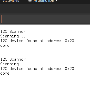
3 sensors with individual addresses on the same I2C BUS.
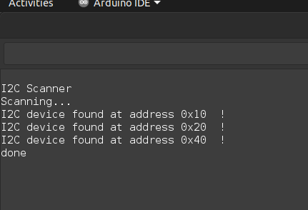
Here’s a clip of all sensors working. I put a sensor up to each sensor. First 0x10, then 0x20 and finally 0x40. When no magnet is detected it defaults to the value 3840.
Lookup Tables
At the moment I don’t have the time to integrate look up tables into my code but I really want to try and bypass a lot of the trig math on my final project with them. Not that an ESP32 can’t deal with it but it’d surely free up resources for other stuff.
This is a nice talk on the power look up tables have:
Conclusions?
This “assignment” might have been the one thing that has brought me closer to insanity, ever. I probably dug my own hole here but at least if anyone else learns anything from all this text it’ll be less slightly meaningful after all the time it took do document all this + Input Assignment - Part II page.
Files
Motherboard - Mega328p - Maybe worth looking into
Motherboard - SAMD21E - Don’t bother, very broken
2022 Fab Academy Logo Milling SVG
Motherboard - XIAO ESP32-C3 - Works, some mistakes