10. Mechanical Design, Machine Design
Editor’s note 2023
This was previously assignment 12.
2022 - Vinyl Cutter
Since I was the only new student at the lab the group assignment is always weird. I looked for a group I could join but didn’t find one. In the end Filipe my instructor did part of the work with me. Filipe wanted to try and build a vinyl cutter with old parts from a big office printer. I started thinking if it was possible to extend on what Dan made with his Foam Crawler and make it kinda modular in a way that it would have 2 edge parts and the roller modules could be added or removed to extend or compact the cutter.
In the end we didn’t have the parts and just made a small vinyl cutter that almost works.
Group - Mechanics
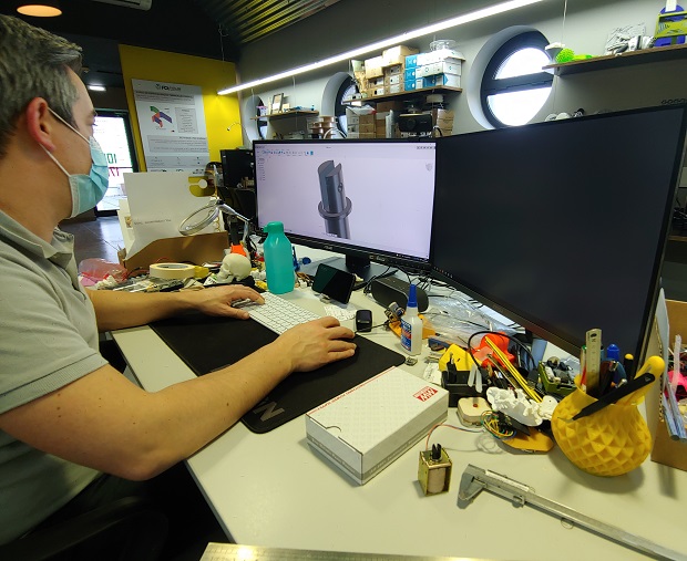
Filipe was responsible for the modeling and hardware side since he knew better what materials and parts were available. My help was minimal.
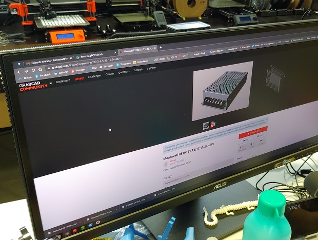
Some models he got out of GrabCAD which seems nice. There are a few websites out there with free models that can save us some work.
All modeled up.
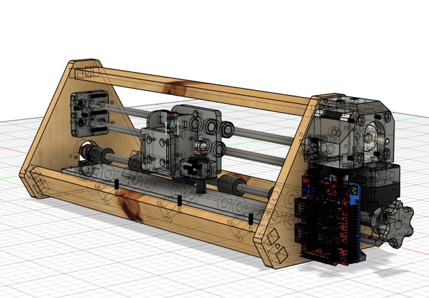
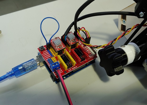
One thing neither of us noticed was that the way the Arduino support was modeled it would make it impossible to connect the USB cable so it had to be left freestanding.
A small belt to keep things compact.
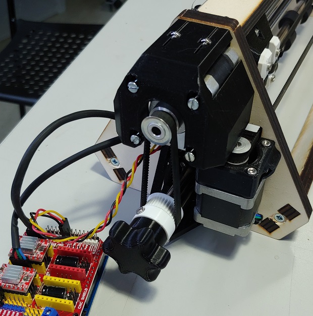
Solenoid holder isn’t super rigid but it doesn’t need to be.
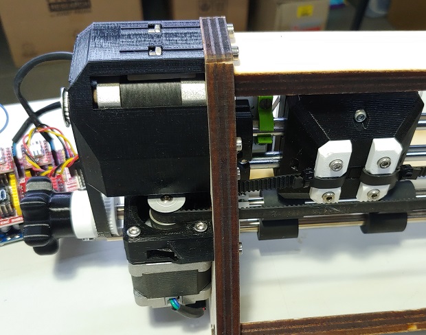
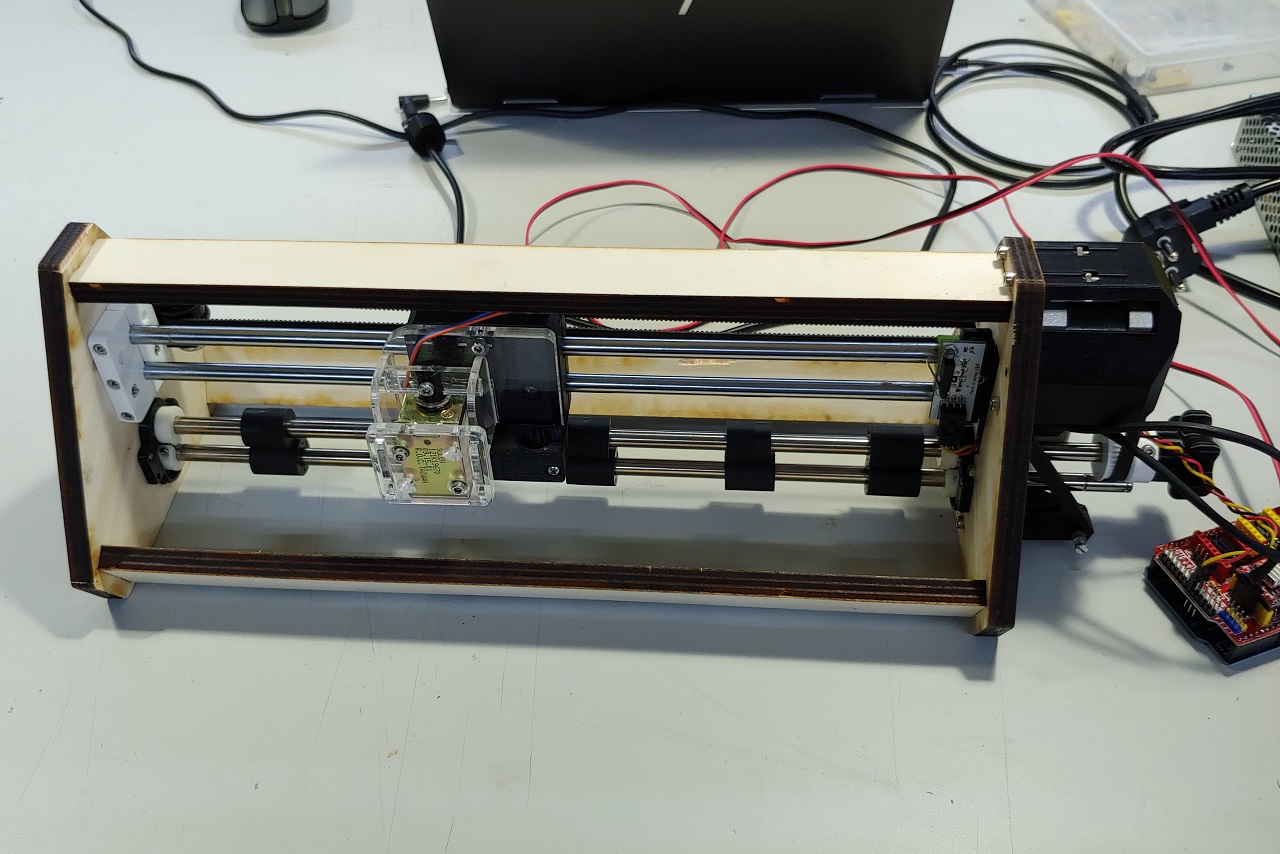
It should work?
Individual - Electronics and Software
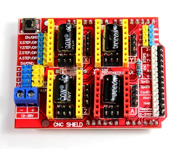
On the electronics side we had a CNC shield so I focused on understanding how it worked. There are a few tutorials and videos online, I liked this one: Direct link
The shield can take 4 drivers for 4 axis. On a regular 3 axis machine the 4th axis can be a clone of another to help distribute the load.
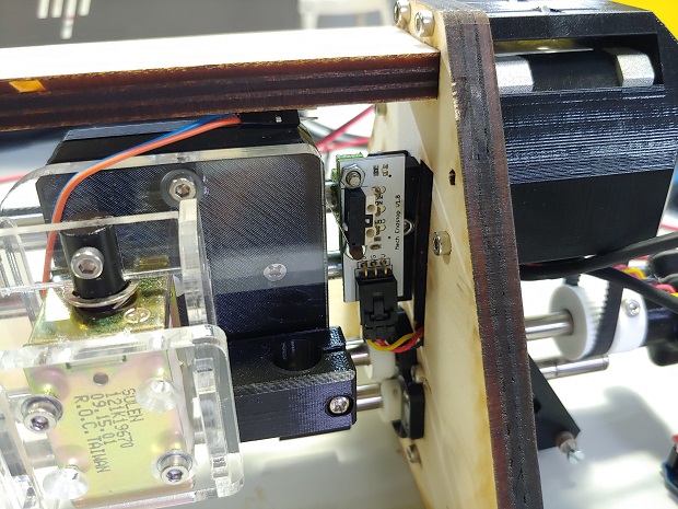
One limit switch for homing the X axis.
The shield on it’s own. They’re pretty cheap considering.
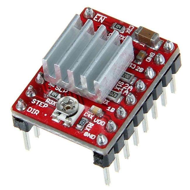
A4988 stepper driver. Made by Allegro. 8-35V and up to 2A of current. Should be limited to 1A without a heatsink if I recall correctly.
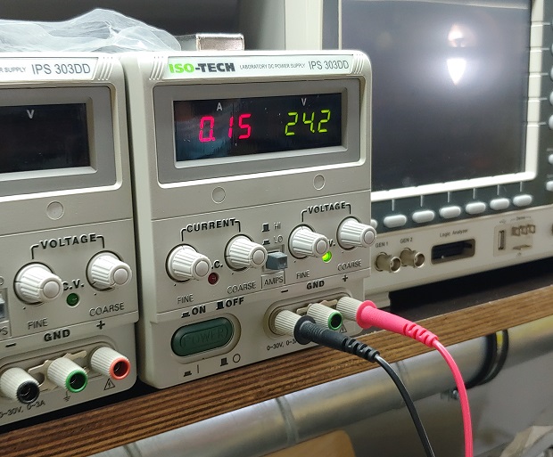
We didn’t have specs for the Solenoid so we had to test it. Also see how it would behave with a spring and where we could put the spring.
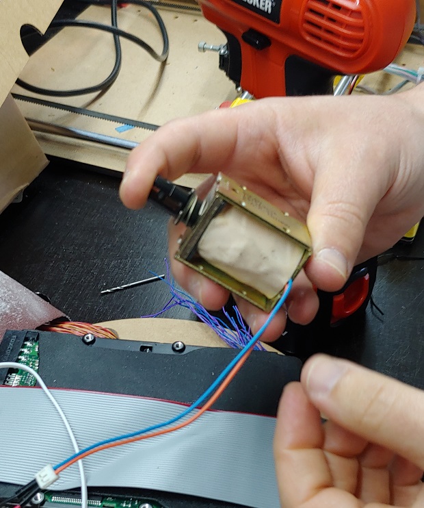
The spring location also interfered with how much strenght we could get out of the solenoid. The power supply was just 24V.
After that we need to load Grbl into the arduino. You can follow the instructions on the Grbl Github page.
It hasn’t been updated in a while but Grbl Recent Releases are here, so go ahead and download the latest one.
Load up the example.
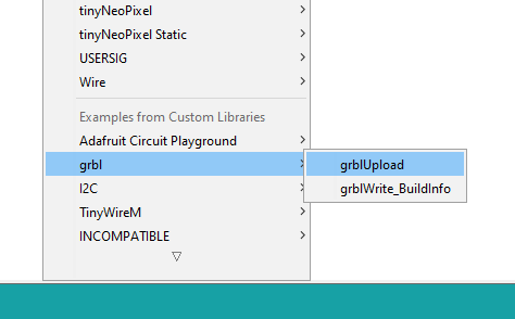
And do as it tells us. Don’t mess with it!
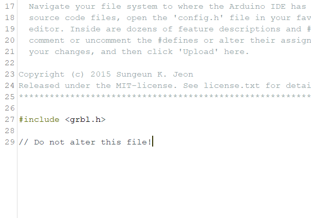
Upload it.
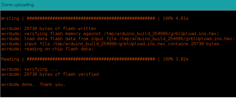
And it works!
Next Steps
We didn’t have the time (or parts) to move the solenoid in the end. I even found a nice tutorial. But no 24v transistor or relay.
Files
Vynil Cutter - Fusion 360 Assembly File
2023 - Shop Vac
Since last year was a bit of a mess and I didn’t know if I had enough documentation for this assignment I ended up joining a group and help out a bit just in case. Between the 2 this better be enough because I really want to graduate this year :|
Group Page
I joined the group from the MSI Chicago Wanger Family Fab Lab. Group Page Link
Funny enough most of their students were also remote. You can find a quick overview of the group effort here.
Individual
Got the electronics hat again.
Planning
Jayson made a Notion site to help us keep track of things to do.
To automate the ShopVac system I initially planned to use an ESP32-C3 Xiao module like the one I’m using on my final project since it has Wifi and Bluetooth.
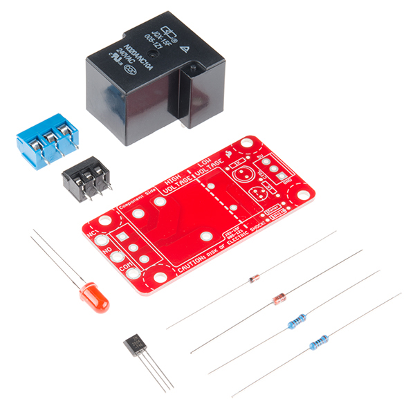
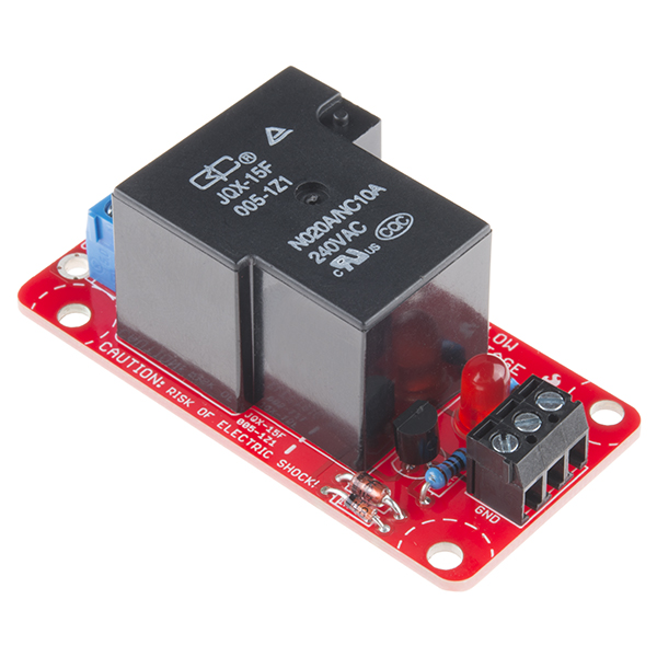
I ran into a problem because the relays Kyle-Pierre and Walter had was a Sparkfun Beefcake Relay and it’s product page starts with Your 5V system can wield great power with this big, beefy relay board. Which is problematic because the ESP32-C3 has 3.3v logic....
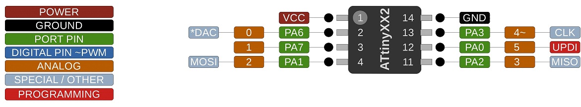
So I ended up changing the MCU to a Tiny 412 since Walter had those too.
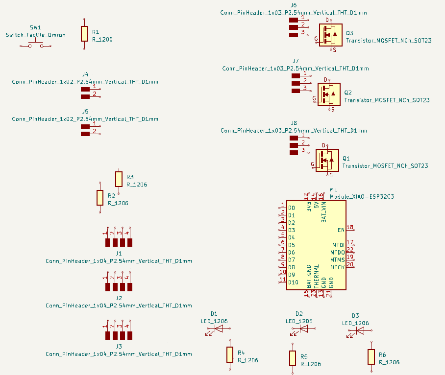
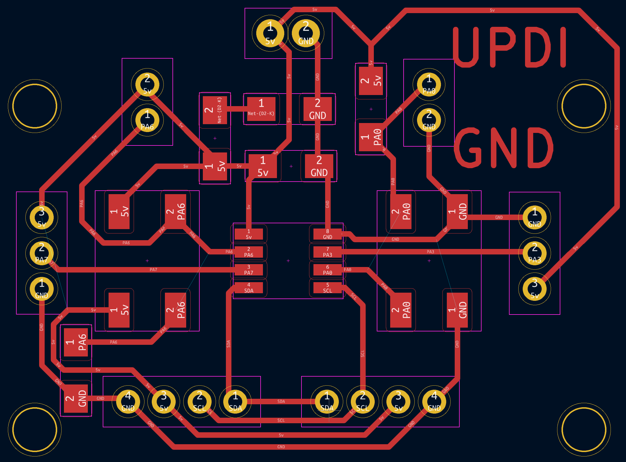
Easy schematics. Couple of 3 pin headers to connect to the sparkfun relays. One for a shopvac and another one for what ever. Maybe a coolant pump or air compressor… A couple of physical buttons and 2 pin headers so they could be put on a sort of wired remote further away from the controller. Like safety shut-offs. And 2x 4 pin headers connected to SDA and SCL for I2C because why not.
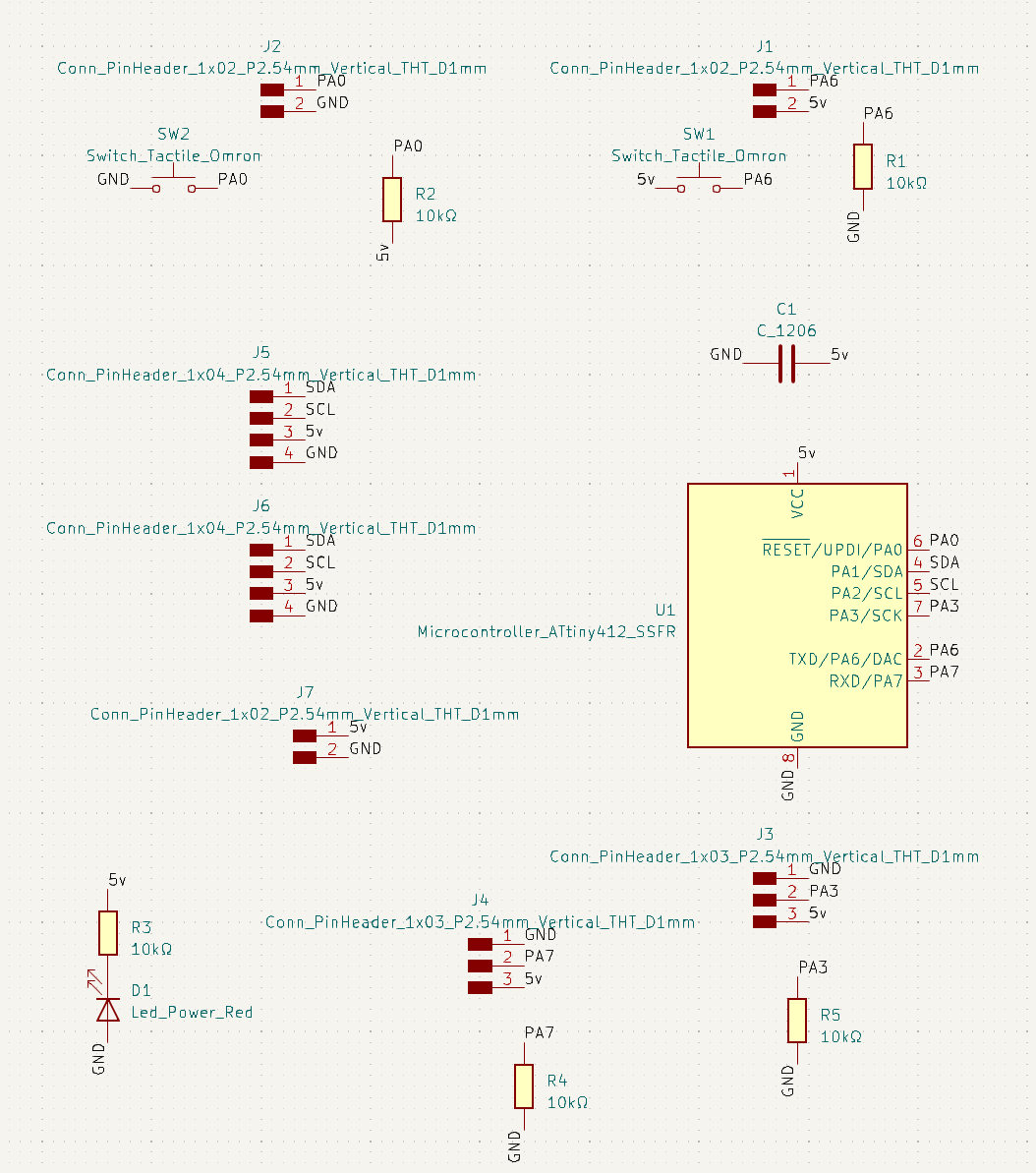
Routing was harder than I expected.
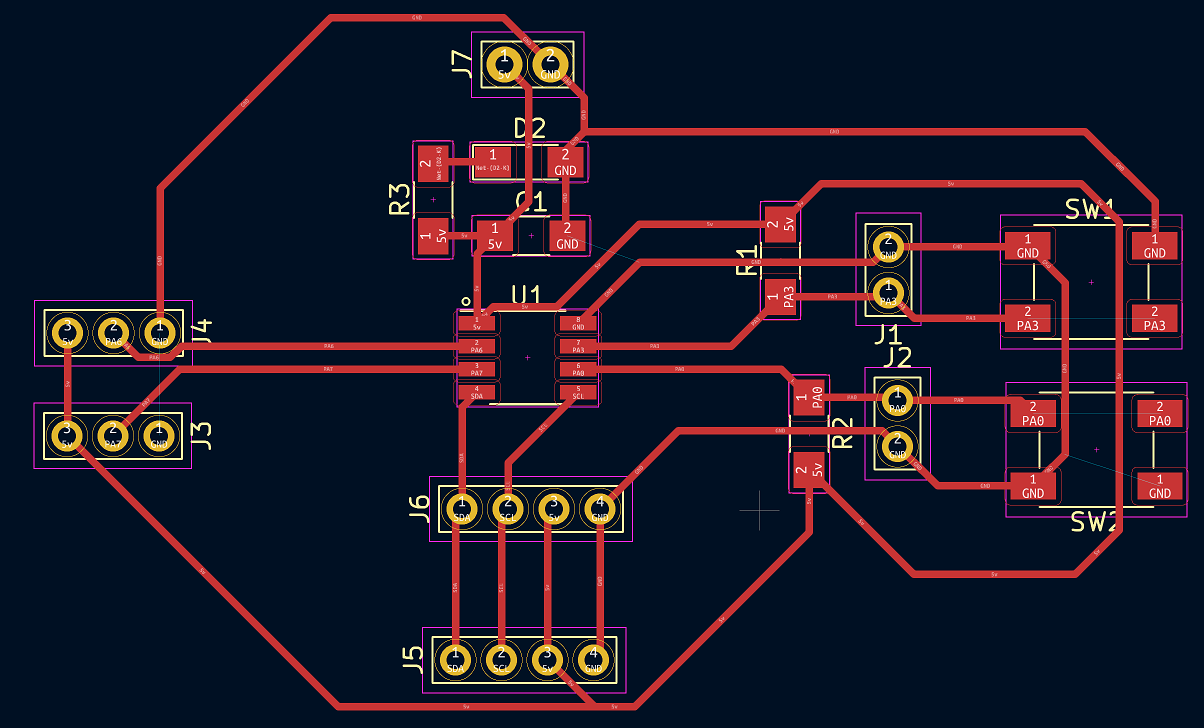
But I got there.
The funny thing was, in the end after asking about safety pull-down resistors to Neil I wento to check the schematics for safety pull-downs on the relay control line and they only had a current limiting resistor on the line. But. But… What it does say is the lowest voltage for it’s integrated mosfet to be open. And it was 2.6v… I could have still used the ESP32-C3 module…
Code
Wrote this quick and dirty, since I didn’t mill the board I’m only 95% sure it should work.
// constants won't change. They're used here to set pin numbers:
const byte buttonPin1 = 5;    //UPID // the number of the pushButton 1 pin
const byte buttonPin2 = 6;     // the number of the pushButton 2 pin
const byte relay1 =  3;      // the number of Relay1 pin
const byte relay2 =  0;      // the number of Relay2 pin


// variables will change:
// Button 1
byte buttonState1;          // variable for reading the pushbutton status
byte buttonCounter1 =1;       // variable for counting button presses
byte lastButtonState1 = HIGH; // to count the 1st press correctly we need to input the status of the pin acording on the resistor used (pull-up)
// Button 2
byte buttonState2;          // variable for reading the pushbutton status
byte buttonCounter2 =1;       // variable for counting button presses
byte lastButtonState2 = LOW; // to count the 1st press correctly we need to input the status of the pin acording on the resistor used (pull-down)

void setup() {
  //Pin Initialization
  pinMode(buttonPin1, INPUT);
  pinMode(buttonPin2, INPUT);
  pinMode(relay1, OUTPUT);
  pinMode(relay2, OUTPUT);
}

void loop() {
  delay(25); //debounce?
  // Button 1 Check
  buttonState1 = digitalRead(buttonPin1);
  if (buttonState1 != lastButtonState1){ // Checks for a change in pressButton1 pin status
    if (buttonState1 == LOW){ // If the new state is low (because of the pull-up resistor)
      switch (buttonCounter1){ // Runs the assigned commands, in this case there's only an ON/OFF
        case 0:
          buttonCounter1++;
            digitalWrite(relay1, LOW); // Turns off Relay 1
          break;
        case 1:
          buttonCounter1=0;
             digitalWrite(relay1, HIGH); // Turns on Relay 1
          break;
        break;
      } // MAIN CYCLE
    } // BUTTON STATE
  } // BUTTON PRESS
  lastButtonState1 = buttonState1;
  // Button 2 Check
  buttonState2 = digitalRead(buttonPin2);
  if (buttonState2 != lastButtonState2){ // Checks for a change in pressButton2 pin status
    if (buttonState2 == High){ // If the new state is High (because of the pull-up resistor)
      switch (buttonCounter2){ // Runs the assigned commands, in this case there's only an ON/OFF
        case 0:
          buttonCounter2++;
             digitalWrite(relay2, LOW); // Turns off Relay 2
          break;
        case 1:
          buttonCounter2=0;
             digitalWrite(relay2, HIGH); // Turns off Relay 2
          break;
        break;
      } // MAIN CYCLE
    } // BUTTON STATE
  } // BUTTON PRESS
  lastButtonState2 = buttonState2;
}