4. Computer controlled cutting
This week’s assignment has us cutting something on a Vinyl Cutter and to design and Laser cut a press-fit kit that can be assembled in more than 1 way.
Group Assignment - Laser Cutter
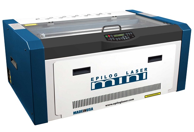
Our laser is an Epilog Laser Mini 24x12 40W.
| Spec | Epilog Mini 24 |
|---|---|
| Working Area | 610 x 305 mm |
| Maximum Material Thickness | 140 mm |
| Laser Wattage | 40 Watts |
| Laser Source | Air-cooled CO2 Laser Tubes |
| Operating Modes | Raster, Vector or Combined |
| Resolution | 75 to 1200 DPI |
| Interface | 10 Base-T Ethernet or USB |
| Max Power Consumption | 960 watts |
| Size (W x D x H) | 876 x 660 x 406 mm |
| Weight | 41 kg - 55 kg w/stand |
The laser corner…
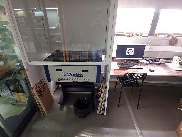
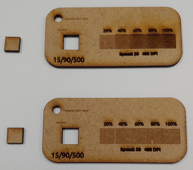
To get aquainted with the laser our Lab I decided to try out some tester boards Adrián Torres had made and showed during one of the Global Open Times if I’m not mistaken.
You can check out his full assignment documentation here.
I downloaded Adrián’s .svg from here
Made some minor changes and they were ready to print.
As the Epilog Laser likes Corel Draw that’s what we use. Open the file and send to print.
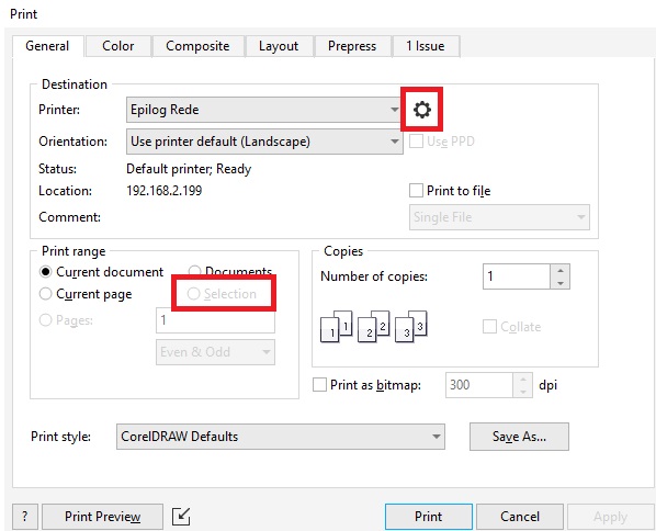
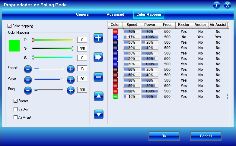
When I took this print screen for documentation purposes I didn’t have anything selected, but in workspaces with a lot of parts being able to selectively print can be really useful. Click on the advanced options next to the printer selection to open the Epilog settings.
My favourite part is the color mapping so we can color code different settings to individual tasks. I did think there should have been a way to save color mapping presets but it might be hidding somewhere else. As our laser is reaching the end of it’s cycle my instructor gave me a few pointers on the settings as the original recomendations aren’t as accurate now. Getting strong cardboard is surprisingly hard here so I’ll be cutting MDF. Not as easily recyclable but it’s easy to find and lasting longer can be a plus in some things.
Press Ok, go over the preview to make sure you’re printing what you want and hit Print to send it to the the Epilog.
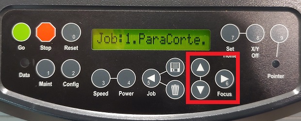
The Epilog explicitly mentions the file name on the job so make sure it’s your job but if it’s the first cut you do that day or after changing materials the Laser focus has to be checked and corrected if needed. Click the Focus button to go into Focus mode.
There’s a little magnetic tab over the laser head that’s used to check if the focal distance is correct.
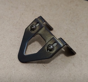
Turn it upside down and tap it a few times and listen to sound. Click the arrow buttons to go up and down but as soon as you hear the tab hitting the material the laser is focused. You can move it up and down a couple of times just to be sure if you want.
Flip the tab, click the Reset button and it’s good to go.
Look at it zooming back and forth.
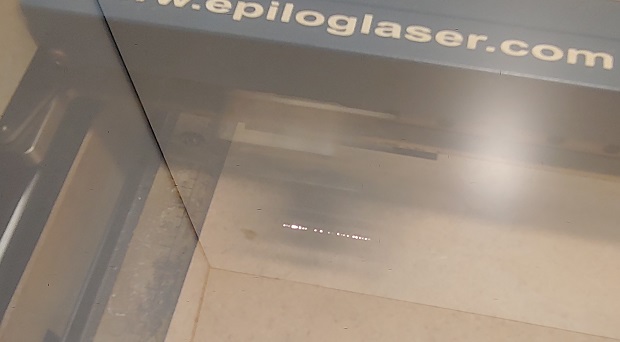
Literally look at it… While it’s working… For safety reasons… Don’t leave the Laser unatended will it’s doing its thing.
Tah dah!
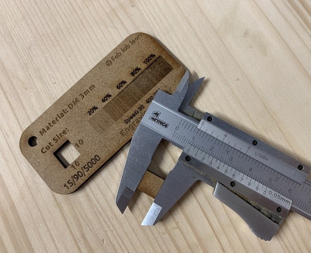
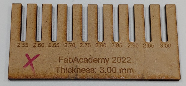
Kerf
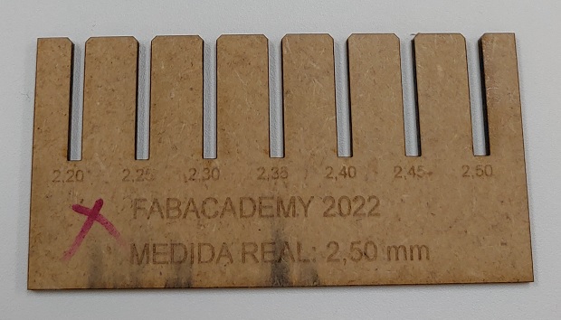
Before cutting the press kit I had to confirm the laser kerf. How much more over the drawing dimensions the laser removes. Unfocused light, material burning/shrivelling from the heat, etc…
Adrián also had showed a good looking kerf test so I figured I’d use it as well.
I got the .svg from here
Got everything ready and cut it.
Minor issue… I forgot I was cutting 3mm MDF so I can’t use this one.
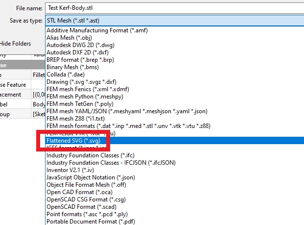
After thinking if I could edit the odiginal .svg I just gave up and modeled one from scratch on FreeCad.
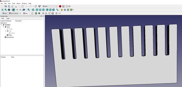
To get an SVG out it has to be Exported as a Flattened SVG.
And to the laser we go again!
Aaaaaaaaaaaaaaaaaand this one is kinda even more useless because the laser did 2 passes. Aparently the svg had double the vectors so I had to clean that up.
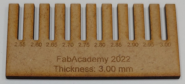
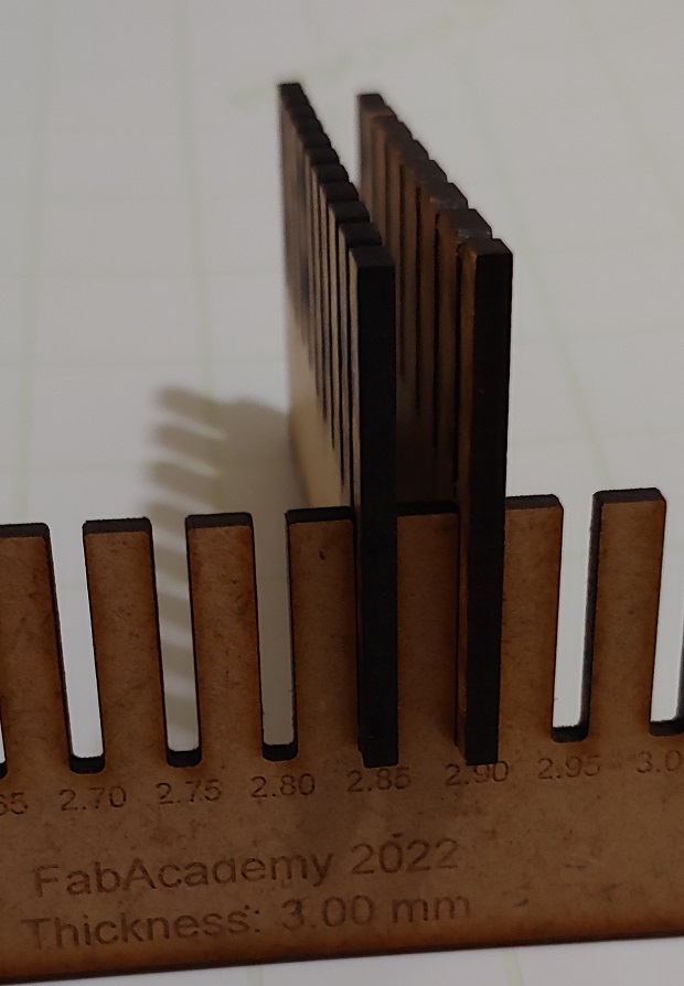
3rd times a charm… 0.10mm is a nice fit that’ll handle modest impact. 0.15mm means something will probably break before it goes.
Individual Assignment - Press Kit
Like last week’s assignment I leaned heavily on what I learned about FreeCAD from Babken Chugaszyan’s segment on parametric design from the weeks recitation about Parametric, Algorithmic, Generative Design. Even more this week because I figured the parametric part Babken modeled would qualify for this weeks Press Kit assignment.
I do recomend taking a look. If you want to see it here’s a link and it should be embedded below as well:
Building on what I did last week I didn’t do anything too fancy beyond what I tried to do last week but modeling the symmetric parts did mean we could do a Radial pattern with the Polar tool.
First link the Angle on the original sketch:
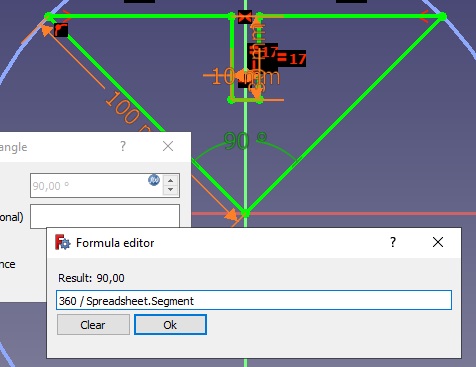
And the number of segments in the Polar tool
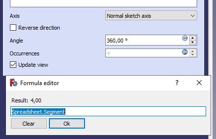
To your spreadsheet
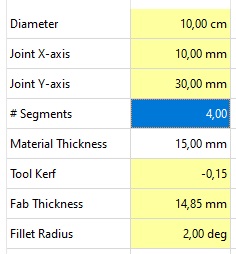
This way it’s easy to change the number of segments by editing that single value in the spreadsheet.
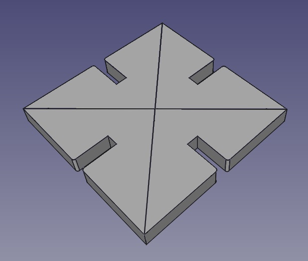
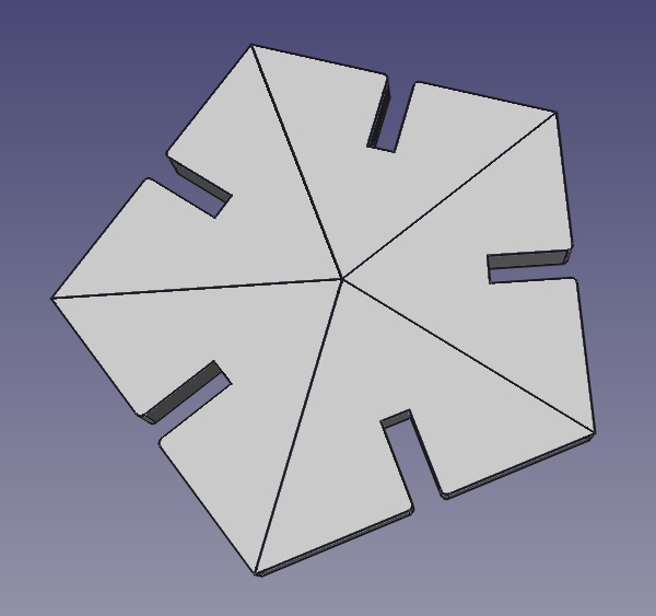
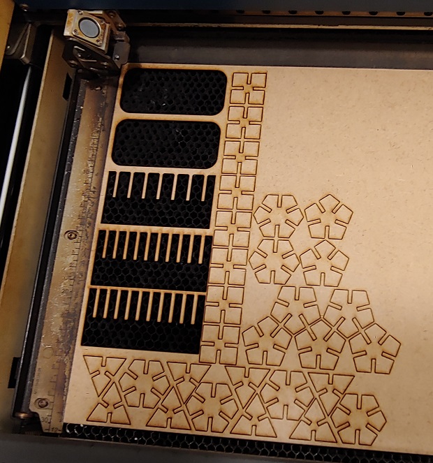
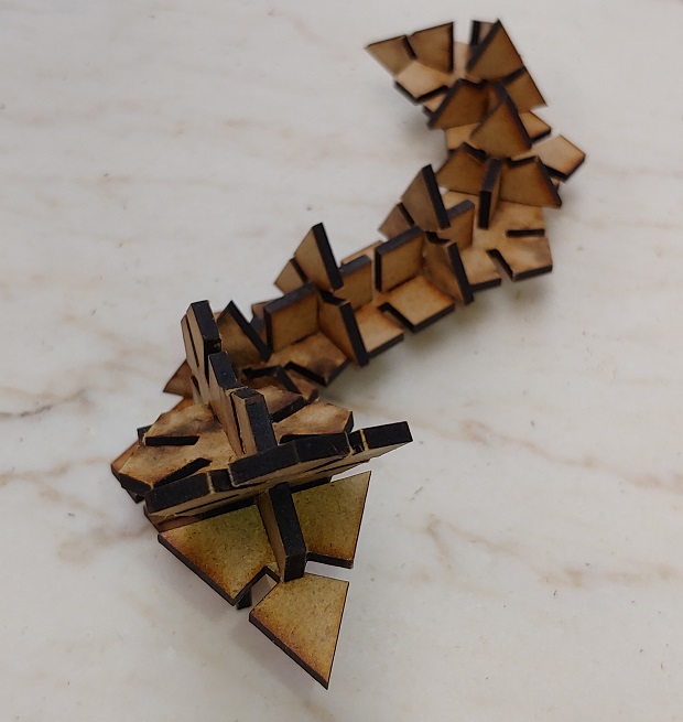
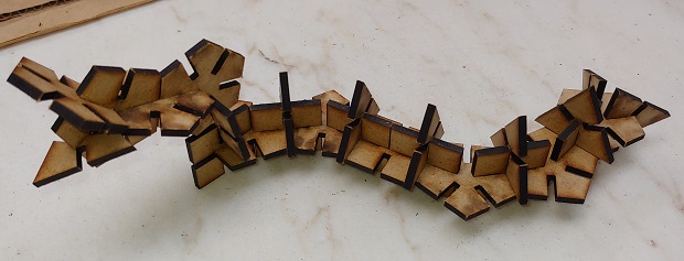
Went back to my Press Kit file and as I changed the segments from 3-6 I again exported each one as individual Flattened SVGs, nested a bit and hit cut.
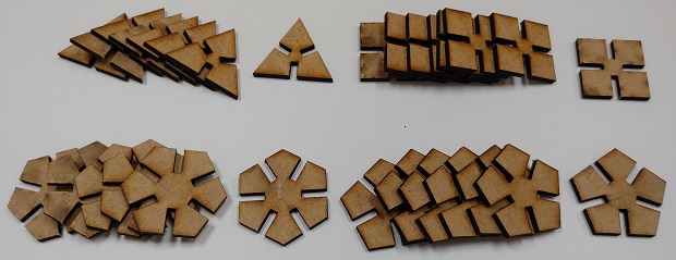
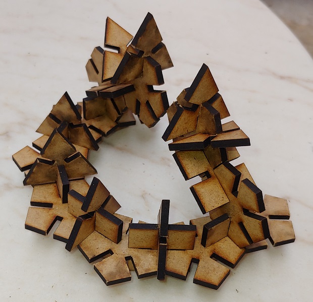
And now assembling it in a couple different ways.
Vynil Cutter
The FCT FabLab @ the Almada Campus of the Nova University is quite compact so the vinyl cutting setup is pretty simple. Just the plotter plugged into a computer.
Cutting Plotter corner:
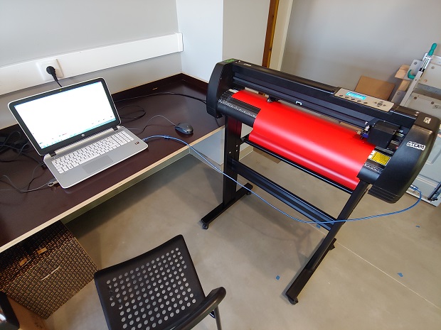
The Cutter itself to be a generic OEM Cutting Plotter with no visible branding, on google images I found a couple brands (Vicut/SinoVinyl) that seem to sell or have sold similar ones. 630mm width.
Update 01/02/2023
After being encouraged to again try and find out more about the cutter I once again searched for “generic chinese cutting plotter” and that led me to another clone that looked identical to the cutter at FCT. The brand is USCutter, model MH 24.
But they had specs:
| Spec | "USCutter MH24" |
|---|---|
| Max Cut Width | 630mm / ~24inch) |
| Blade Type | Roland Compatible |
| Max Pressure | 350g |
| Max Speed | 1m/s / ~39inch/s |
| Interface | USB |
And they even had a manual:
Which is neat.
As I had a few issues in the 1st week I just wanted to cut something as soon as possible to move on to the next task so I just went to DuckDuckGo and looked for websites with free .svg files to grab one and throw at the printer.
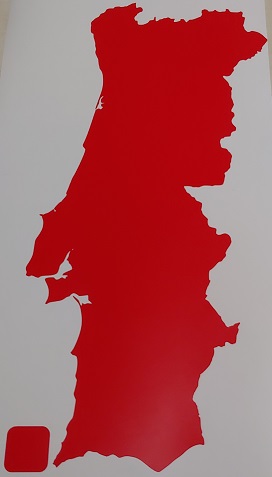
The first decent one I found was SVGsilh. After spending about 30mins running around I was suggested an svg that reminded me of Portugal. As I’m not a stickers on my laptop kind of person I figured a big sticker with the outline of Portugal could at least be kinda useful… Somewhere…
This is a link to the original pages. but do keep in mind the original file had hidden geometries that the printer drivers couldn’t solve but it was just a matter of un-grouping everything in which ever program you use, moving the big outline out of the way and selecting/deleting what ever was left. If you get a random .svg from a random website give it a check before printing to make sure there’s nothing funky. In my case it was just a couple of tiny irrelevant islands and an unrelated round blob at the top.
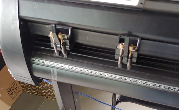
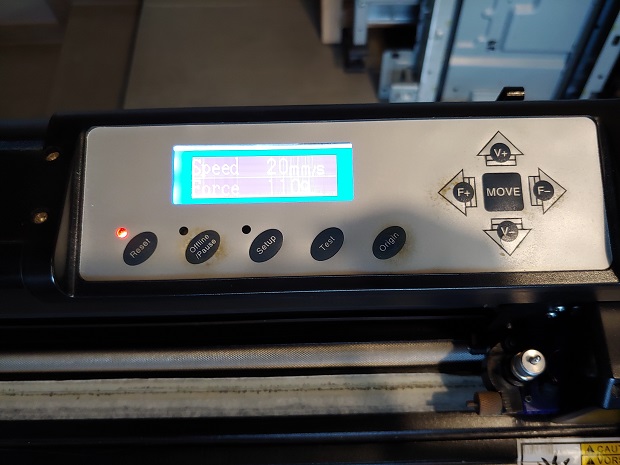
To load material into the plotter we need to make sure it’s aligned and fix it with the roller clamps.
Not a lot of fiddling needed with the settings, 20mm/s and 110g of force.
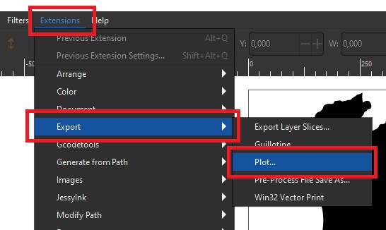
The drivers were configured to work with Inkscape so looking inside the Extensions menu -> Export -> Plot…
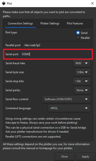
Next make sure it’s trying to connect with the correct port. My first couple of tries failed because the printer was moved and the USB cable was now connected to a different port.
Once we hit apply the job is sent and the printer starts. No more confirmation screens or questions from the Cutter.
After removing unwanted parts it’s all done!
Files
The raster settings tests are from Adrian’s test file