9. Electronics production
Editor’s note 2023
This was previously assignment 5.
When I started working on this documentation I figured I just had to re-tell what me and my instructor did. He put a programmer together on EasyEDA, helped me mill it and we eventually got a program to take the bootloader and burn the fuses. But aparently I didn’t need to add this much information. Welp too late now…
This assignment was such a mess, I couldn’t get a stuffed programmer board working, had to do a few different ones and the errors I got on both Windows and Linux were insane. Everything was moving so fast just tryig to get back on schedule that I didn’t document all the things that went wrong. It wouldn’t be of much use because I didn’t find a solution to any of them, it just worked one time on Linux when all the others didn’t.
Group Assignment - Design Rules
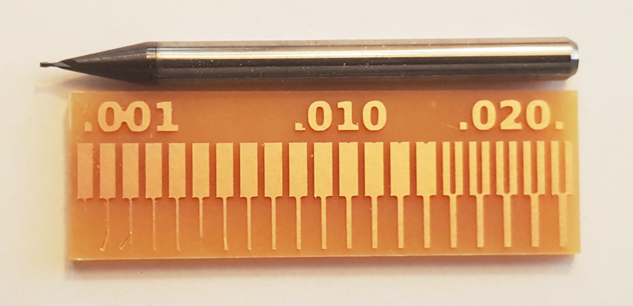
This group assignment involves testing out the design rules for the precision CNC. Knowing the lower limits of what the machine can do with the cutting tools we have access to will affect how we design the PCBs later.
Prof. Neil has made a line test image that we can use to test our machines. They’re available in the class page.

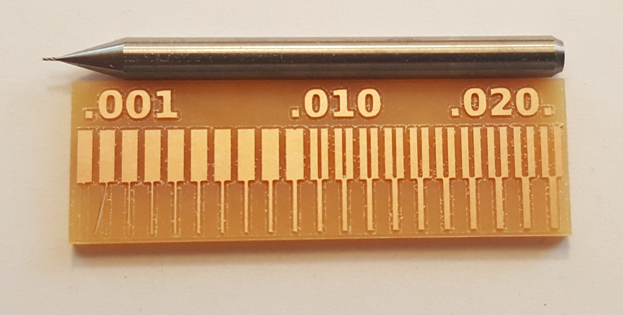
Also a few examples with different bits, a 0.15mm:
And a 0.10mm:
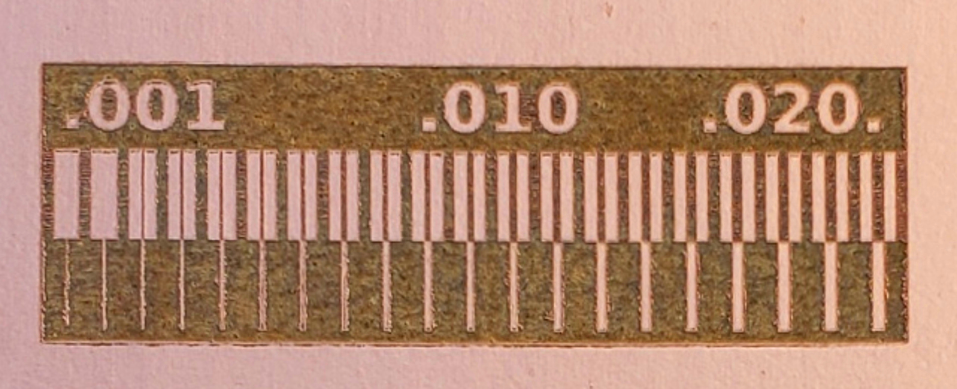
And cheating with a fiber laser… Although I don’t think I’d trust the laser for really fine trace isolation as it seems to still leave a lot of copper behind. Looks like fixing shorts would be a nightmare.
Personally I don’t like that test because it forces us to use Mods which I never really used before and since I have limited time this year I figured it would be a safer bet making an .svg file from scratch.
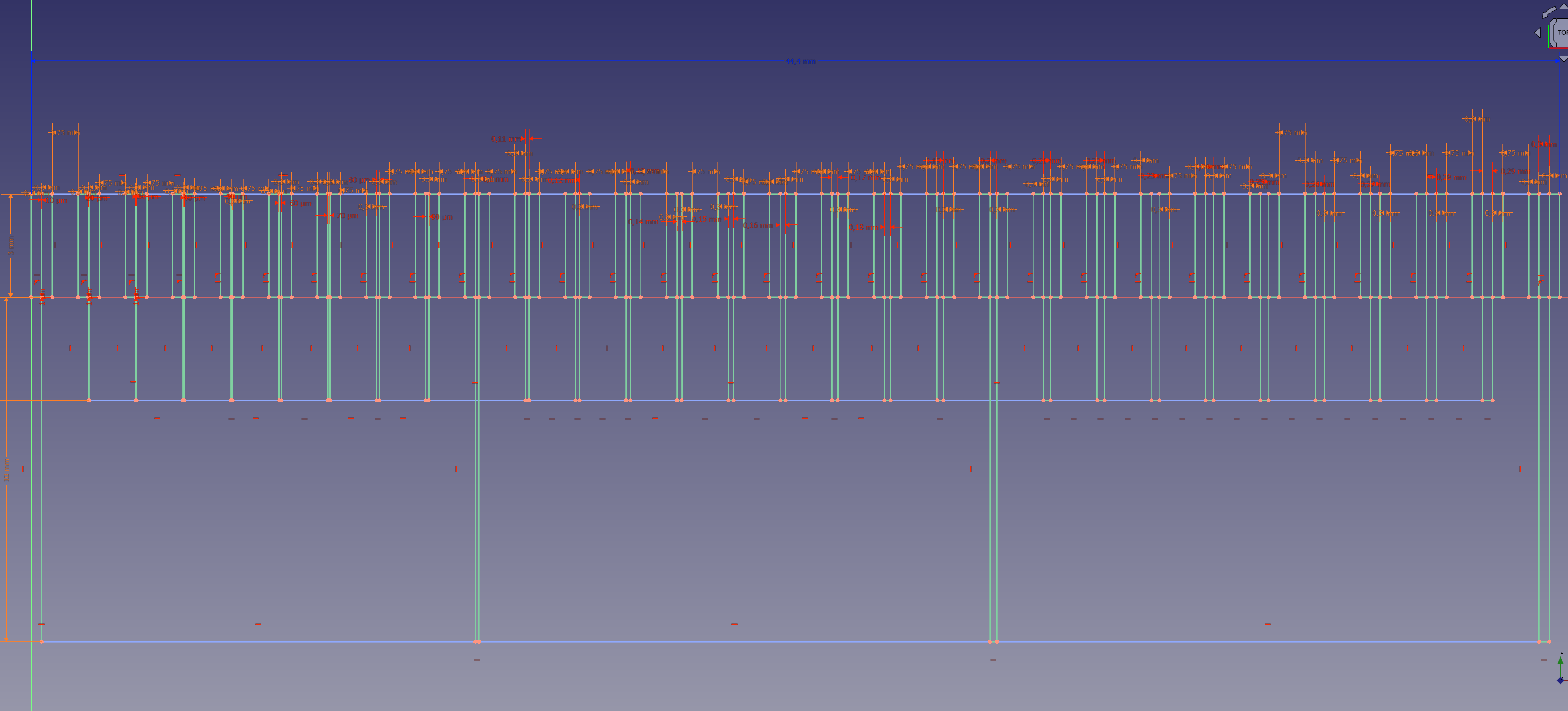
Now I can use other CAM options like FlatCAM. This way I’m pretty sure I’m not breaking any bits mid job. My version also goes up to .3mm diameter. Bit more realistic for cheap v-bits many of us use, no pun intended.
Drag and dropping the .svg works fine, just be careful picking the correct offset in relation to each .svg line and changing to the correct pre-processor. The M06 g-code command tells the machine to change tools and that makes most machines crash on that line even before starting.
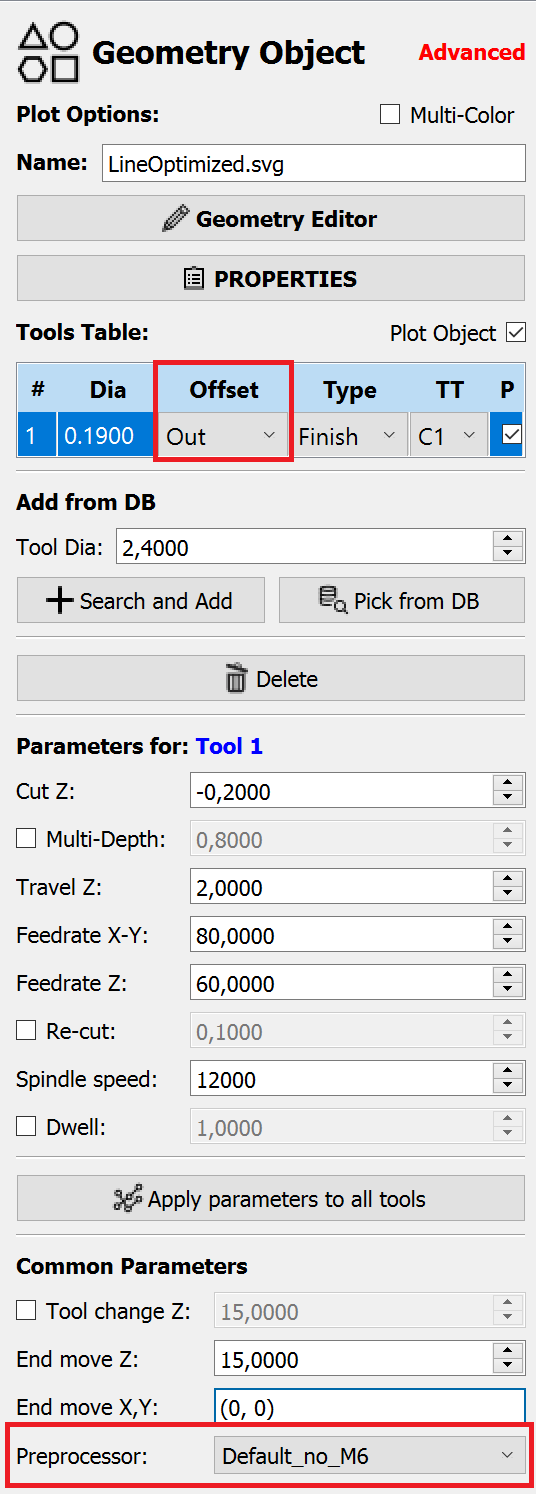
Probably too optimistic on the v-bit width and too conservative on the feedrate but only one way to find out:
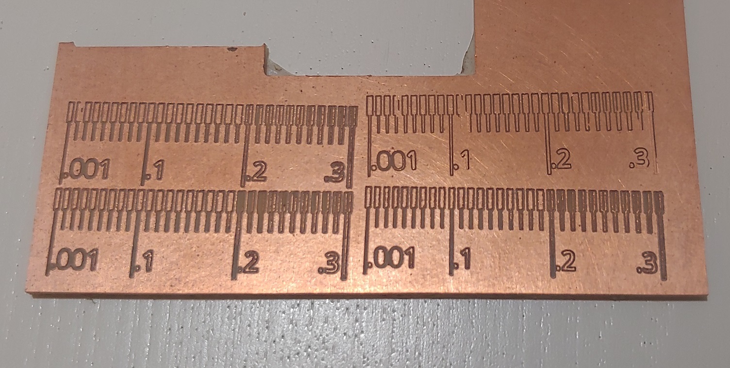
Tried it 4 times until I was happy with how they came out. I started at 0.2 depth was too much, went down to 0.18 and 0.16. Last one was just 0.1. The final v-bit width I went with was 0.25, forcing 0.19 was fun but pointless. I felt the lines were a bit squigly… Don’t know if it was just the limits of the machine or if the values from my svg had too many decimal points and that was causing problems within FlatCAM with rounding errors. I need to find a better way of exporting flat svg’s out of FreeCAD.
Bit still missed isolation in a few places. Next time I make a PCB I’ll have to try a bit more for consistencies sake.
In the end it also clicked why v-bit calculators need to know the size of the tip and that without a way of measuring it both width and depth values will always be a bit of a toss-up.
Individual Assignment
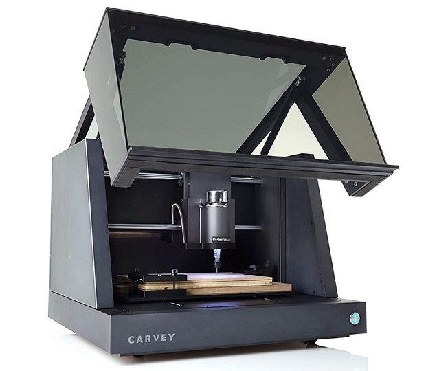
The precision cnc is a Carvey by Inventables. They have been discontinued a while back. Ours was slightly modded by my instructor.
| Spec | Carvey |
|---|---|
| Working Area (W x D x H) | 290*200*80mm |
| Maximum Z Clearance | 90 mm |
| Axis Resolution | 0.0254mm |
| Router Max RPM | 3.000 - 12.000 |
| Router PSU | 300 Watts - 48V |
| Collet | ER11-A |
| Total Indicated Runout | 0,01524 mm |
| Interface | USB |
| Size (W x D x H) | 550 x 520 x 420 mm |
| Weight | 32 kg |
The Carvey corner…
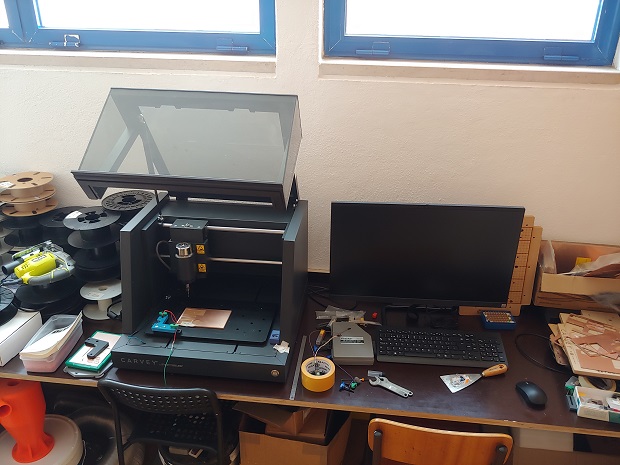
The mods are easy to spot.
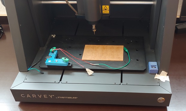
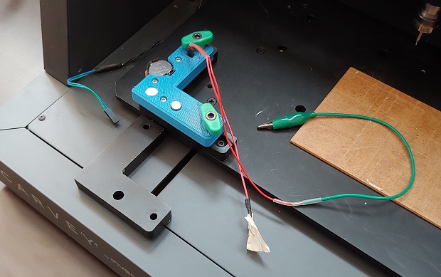
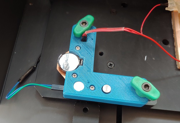
The tool height probe was modded in a way that made surface mapping possible.
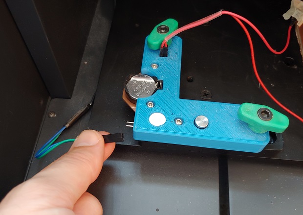
Not entirely sure about the electronics but the machine cable needs to be unplugged after every use or the small CR2025 battery drains out.
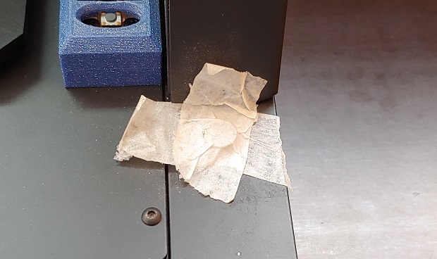
Small magnet on the door sensor so the machine can function open and let us vaccum some dust or something.
Editor’s Note 2023
As I mentioned before, do ignore the images will be mostly about making my FabTinyISP last year. If you want to see how these files were generated in KiCAD do take a look at Electronics Design assignment here.
CAM
![]()
The software we’ll be using is FlatCAM.
Do be aware that website is old and the domain is misconfigured. It won’t connect if your browser forces HTTPS.
The latest versions can be found here
You’ll notice that there hasn’t bee much activity lately which is a shame.
With the Carvey 8.5 is a safe bet, but 8.994 is way better is loads of fixes. Thankfully someone pre-compiled it and uploaded the .exe in 2023. I’ve used 8.994 with 3018/1610 and it works flawlesly. Just make sure to pick the pre-processor without the tool change commands.
It even has a Roland pre-processor but I haven’t had a chance to test it. Probably more customizable than Mods.
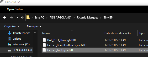
After installing get the Gerbers, those are the geometric data each layer. Chances are you’ll only have a Copper_Front and a Cutout.
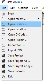
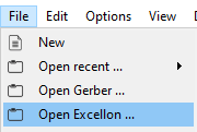
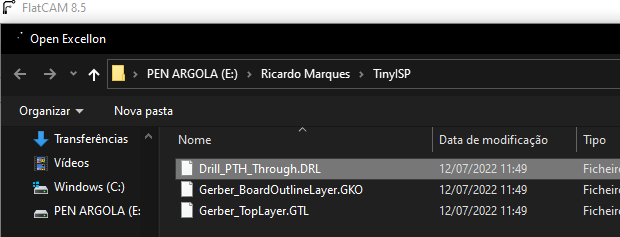
The holes to be drilled are stored in the Excellon file.
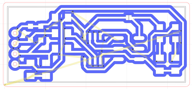
Select the copper layer. The tool diameter shouldn’t be too hard but if you’re using v-bits you might need to run some math.
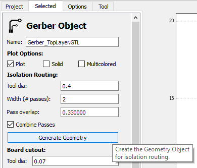
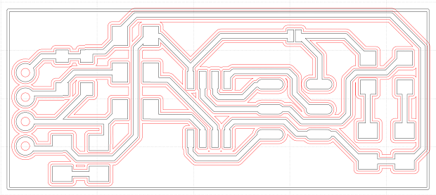
Check to see if the path created clears everything. Sometimes if the tool is too wide it’ll fail to isolate traces properly by just skipping sections.
Depth involces a lot of variables when using v-bits since the deeper we go the wider the tool becomes. CNC frame and base/spoil-board regidity come into play as well as we need all the force we can get to make sure the tip of the v-bit punctures the copper every, single, time. If not it’ll just scratch the surface of the copper as it also happens when the v-bit is worn out.
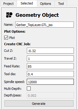
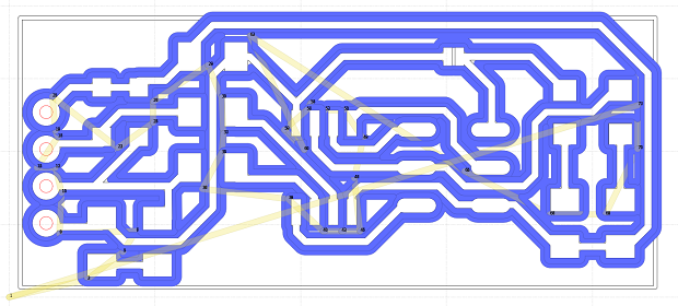
Pressing generate again will update the paths with the tool diameter giving a pre-view of the final cut.
You can go ahead and press the export button.
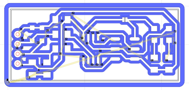
Move on to the board cutout file. For rectangular boards held in place with double sided-tape Bounding box is the best option. Although it won’t allow for custom board shapes.
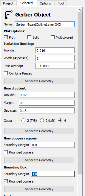
Generate the new geometry.
The board thickness is 1.8mm and 0.3mm depth of cut is very reasonable. That’ll mean 6 passes.
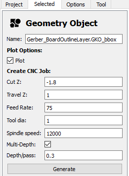
It’ll again show a preview.
Same deal, export the g-code and
Holes is easy. This is the old interface but feed-rate is just the plunge rate for the drilling. Don’t wanna over do it.
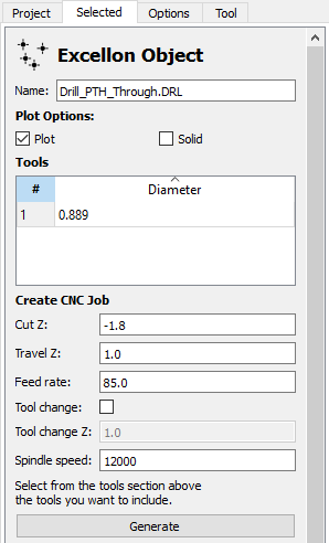
Same tool as cutout and generate.
Tools
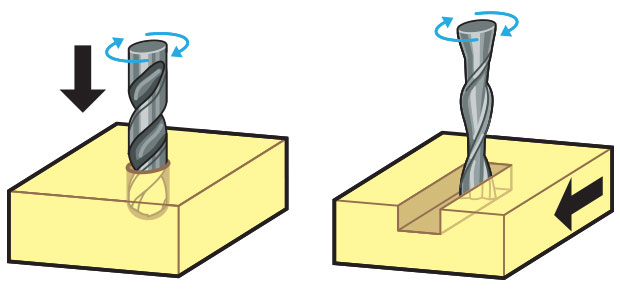
First, what’s the difference between a [drill bit and an end-mill](https://makezine.com/article/workshop/endmills? It has to do with how forces are applied. Drills go straight down while end-mills cut to the side.
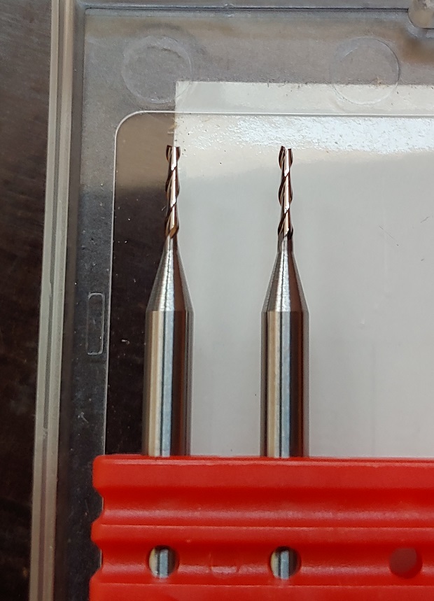
For holes and cut-outs we had 2 flute 1mm wide end-mills.
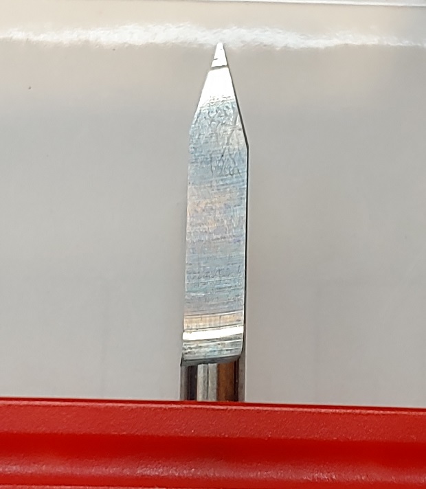
And some v-bits. They usually come in a few diffent V angles but they were running out so I just used the better looking ones.
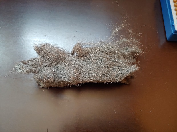
Iron wool for deburring.
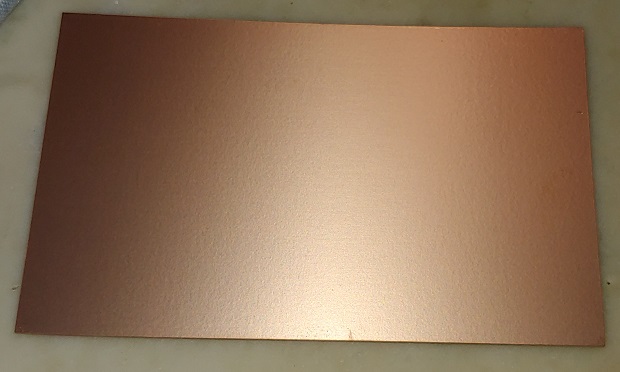
These are the copper plates. 16x10. 30ish microns of copper. These usually come measured in Onces of copper which really doens’t help.
CNC’s regularly have 2 wrenches around. One to grab the collet and one to grab the spindle.
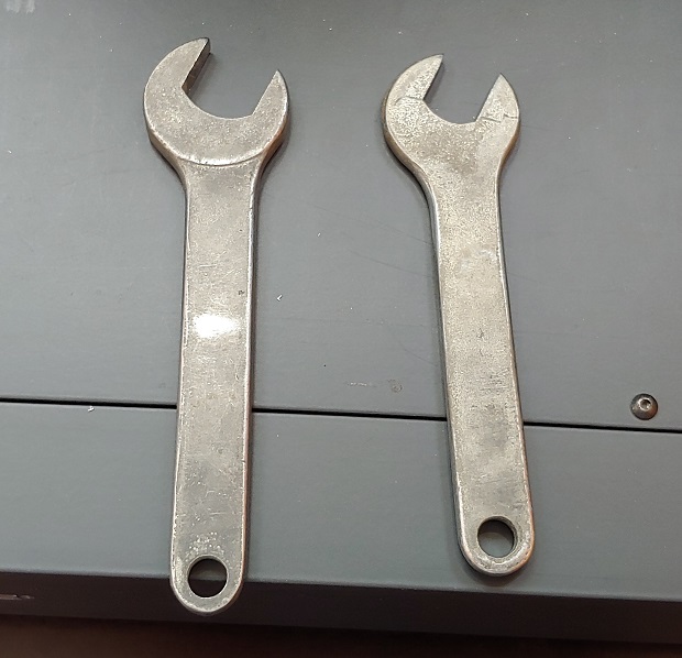
Different sizes.
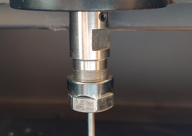
Close up: connect the power in the back.
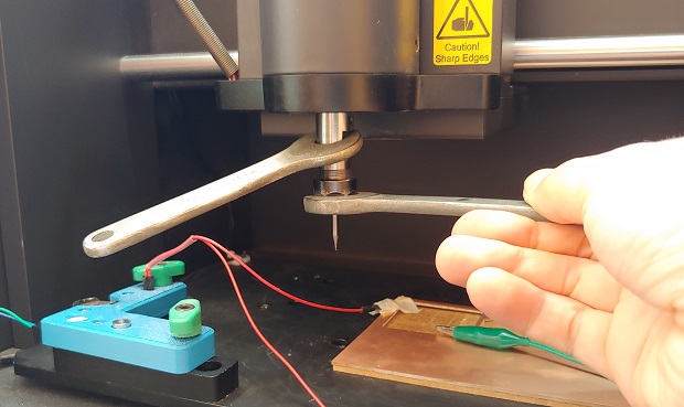
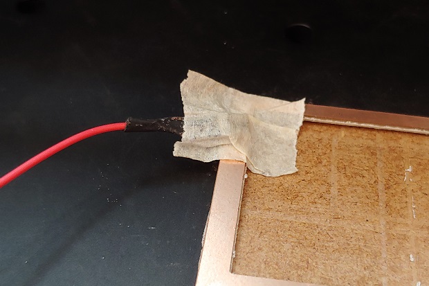
Make sure the connector is well stuck to the copper or the circuit won’t close and you’ll break some end-mills. Happens to everyone…
Touch the copper just to be sure. It’s hard to see but the LED does turn on.
Editor’s Note
Last couple of times I’ve had to cut something I actually just straight up soldered the cable to the copper. Tired those things peeling off and breaking an end-mill. Even just stabbing the board with a V-Bit is bad since it’ll break the tip off.
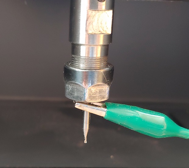
Leave it on the end-mill.
ChiliPeppr
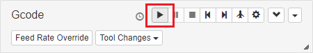
Now we need to interact with the Carvey…
![]()
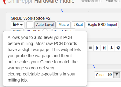
ChiliPeppr’s got us covered.
There are other options like Universal G-code Sender or G-Sender. But the Surface mapping tools of ChiliPeppr are still the best.
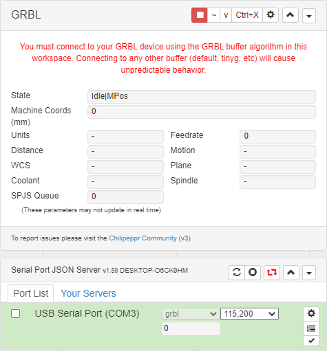
Go ahead and pick the GRBL Workspace. HTTPS also breaks so make sure your browser isn’t forcing it.
There’s a small accessory program called the Serial Server you’ll have to download that’ll make the connection between the browser and the Serial port.
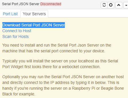
After installing you just need to leave it running in the background.
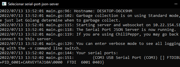
Now you’ll see a COM port become available.
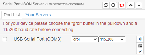
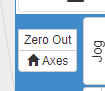
You should be aware the Go to Zero button is extra dangerous on the Carvey as the regular Zeroing out doesn’t work as expected.
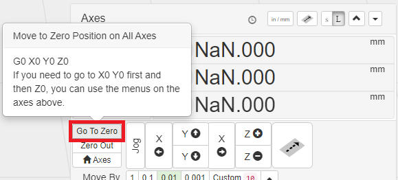
Personally I hid the button div with [uBlock Origin](https://ublockorigin.com/.
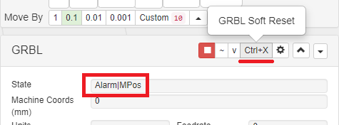
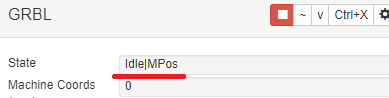
When the machine connects it’ll throw an alarm. Click the soft-reset button.
Now click where it says Click to Unlock ($X)
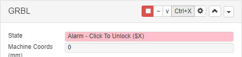
Ready!
Job the machine into place, above where you want the 0 in X and Y to be.

Go to the Auto-Level menu.
And click Run Test Probe.
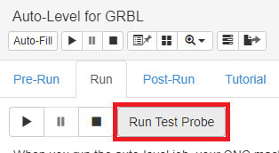
Once it touches the copper and stops you’ll need to turn the Carvey Off. That’s the only way to zero it out properly. Like I said, the Go to Zero button can be very dangerous.

Connect again.
Reconnect and repeat the steps to clear the alarm, again.
Time to Zero out the machine.
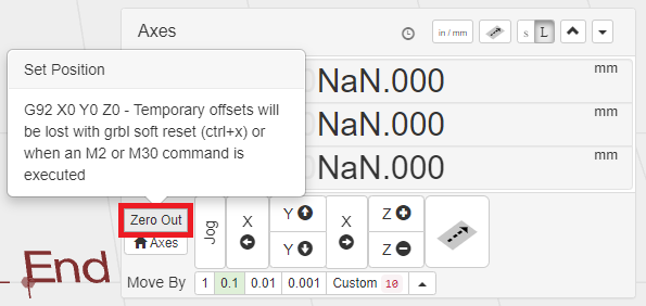
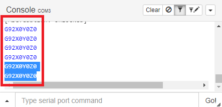
Check the console. Can’t forget this step or it’ll be another broken end-mill.
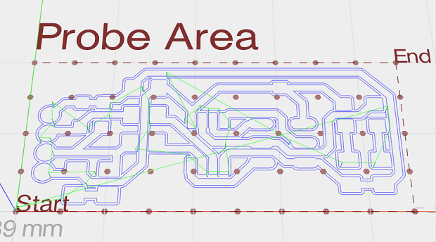
Back to the Auto-Level menu, the Probe area can be customized but it’s easy to understand.
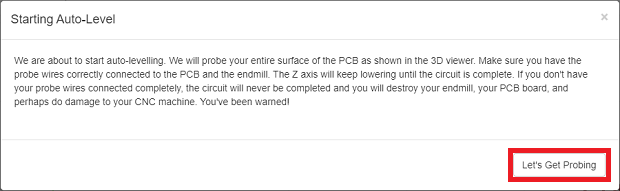
Click the actual start button.
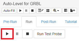
And Let’s Get Probing.
By the end it’ll show you how un leveled the surface really is.
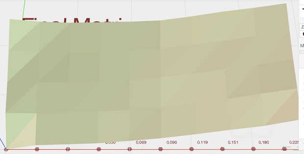
Sometimes it can fail if the difference from highest to lowest point is beyond a set value. Which can be changed, and probably should or it’ll fail all the time unless your pcb boards are all smooshed under pressure to keep straight.
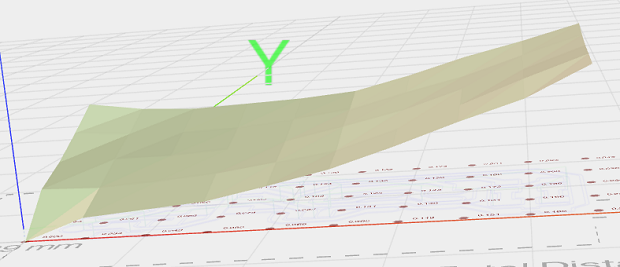
Another angle.
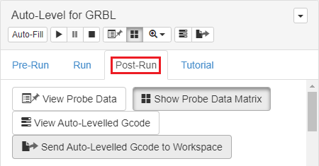
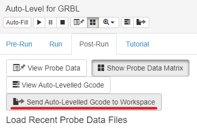
Import part: Post run -> Send Auto-Levelled Gcode to Workspace.
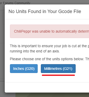
In the correct unit. Probably millimeter. Not the time to mis-click either.
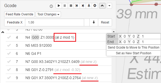
This is the step that updates the Z coordinates in the Gcode so go check.
Unless you want to see sparks flying disconnect the cable from the end-mill. One of the few things I didn’t do in the Carvey…
And click!
And mill!
Soldering Station
This is were all the electronics components and soldering tools are.
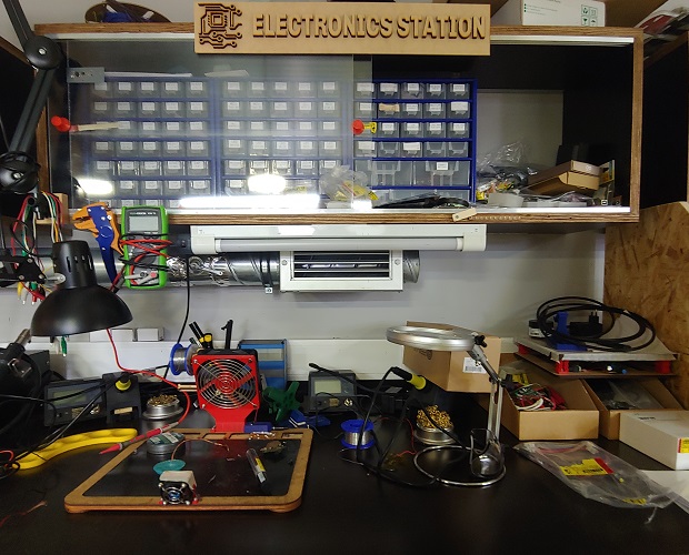
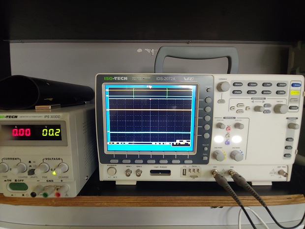
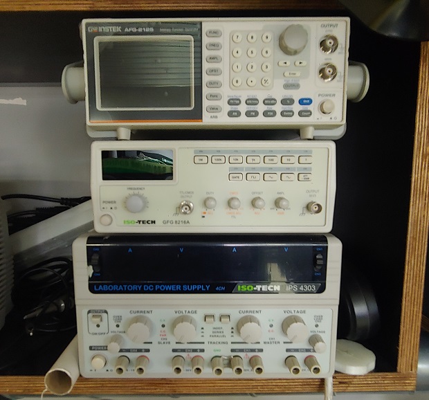
Plus the powersupplies and diagnotic tools too.
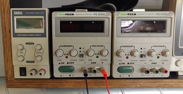
Close up on the power supplies.
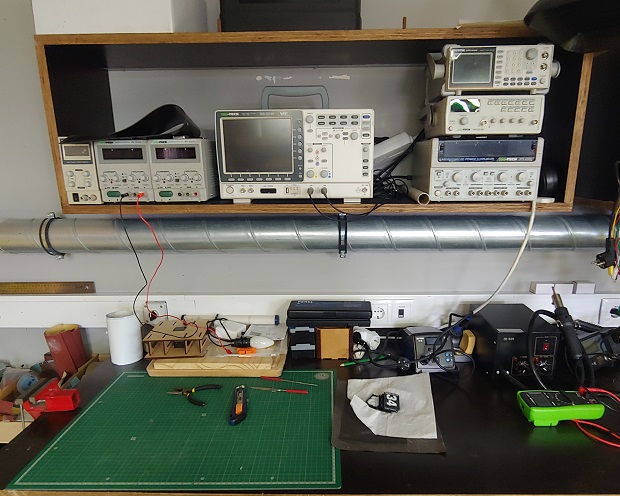
Close up on the Oscilloscope.
Some extra stuff I never used.
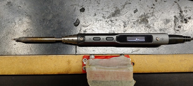
The TS100 Soldering Iron. Lovely thing. I’ve since bought one for myself and shoved in a custom Firmware called IronOS. Highly recomend both.
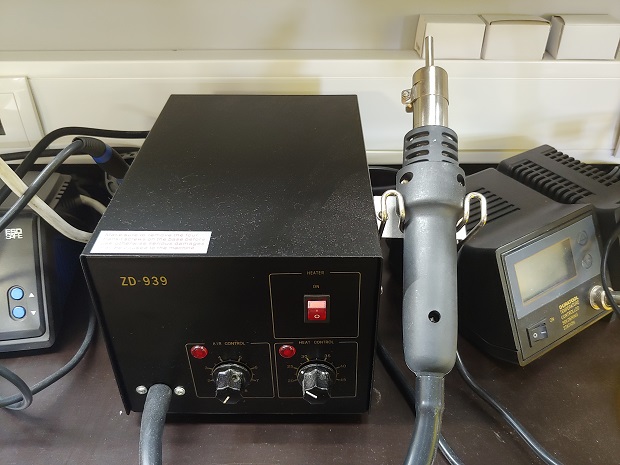
Hot Air Gun. Good for reflow and salvaging components from old bolards.
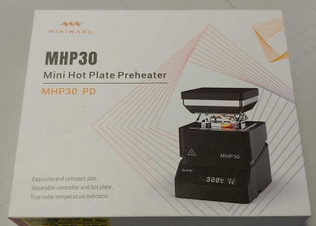
There’s also a small MHP30 hotplate, also for reflow and desoldering stuff.
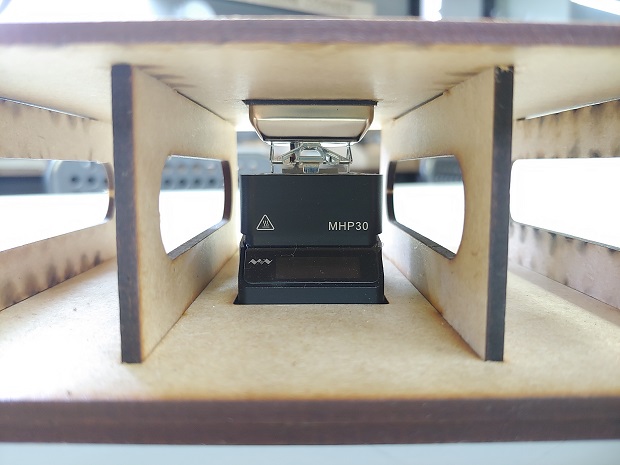
It’s tiny so my instructor made a small platform to help.
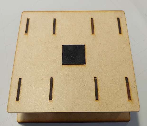
Controls aren’t too easy to get to but it gets the job done.
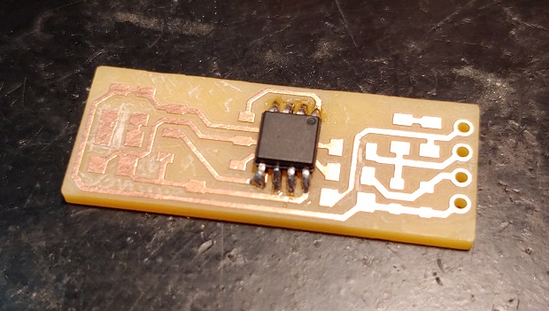
My FabTinyIsp PCB looking nice and photogenic. Needs some deburring.
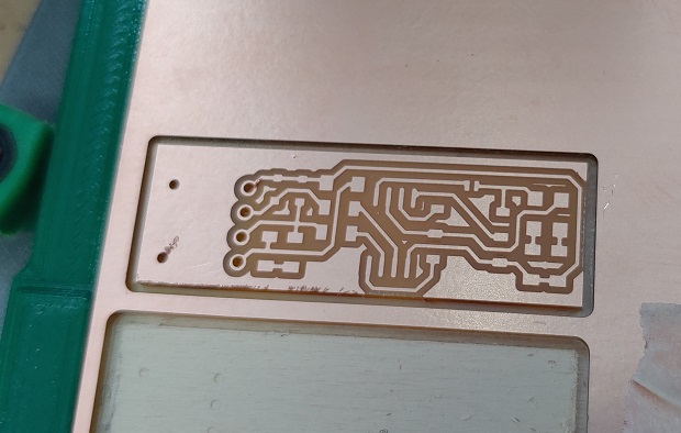
Before soldering anything it should be cleaned in water or Isopropyl Alcohol to remove any oils on the copper from the factory or our hands.

Shinny!
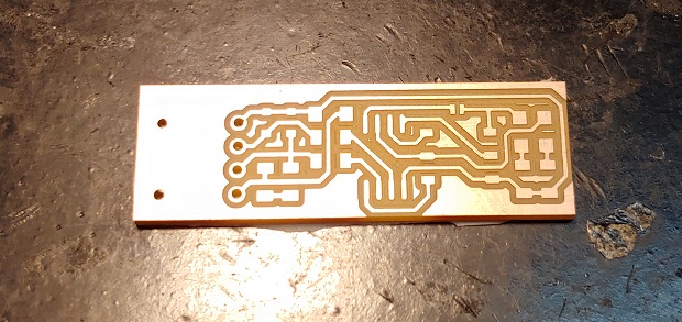
I wanted to remove all the extra copper to make it look my first board extra nice… (Probably don’t bother.)
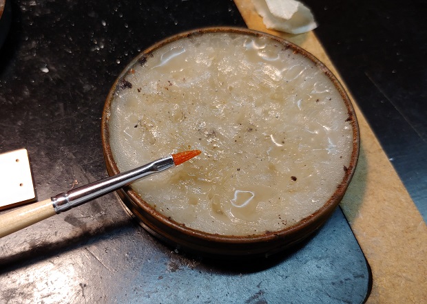
When I started I didn’t know but use flux. Lots of it. Personally I’m partial to the waxy one because the pens dry so fast but you do you. A small paint-brush is really nice to help apply it in small amounts.
Plop a tiny bit of solder on a single pin.
Hold the chip and align it to that pin with the solder, then melt it to fix the chip.
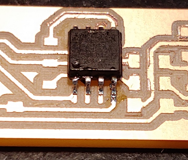
Now leave that one alone and solde the rest. Add a bit more solder to the 1st pin if needed.
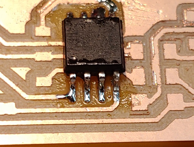
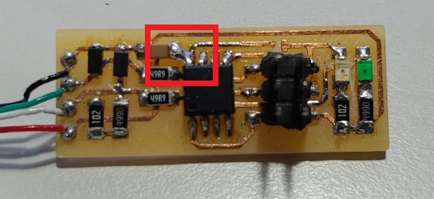
My first micro-controller!
Stuff everything in.
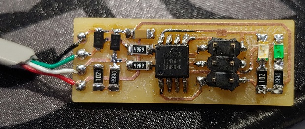
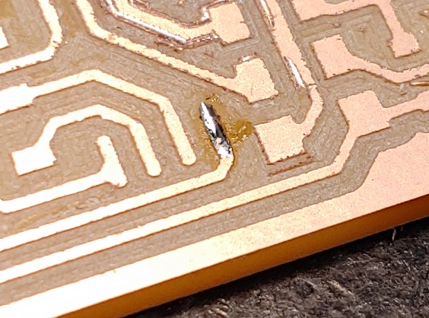
Later on I actually found a problem in the circuit and had to McGuyver a connection for that capacitor. Not sure what could have happened.
Using the FabTinyISP
This bit traumatized me. I still have no idea why it didn’t want to work, nor why it eventually did work. Anyway you should start by reading these instructions here.
If you use Windows there’s an extra set of Instructions here
Download and unzip everything.
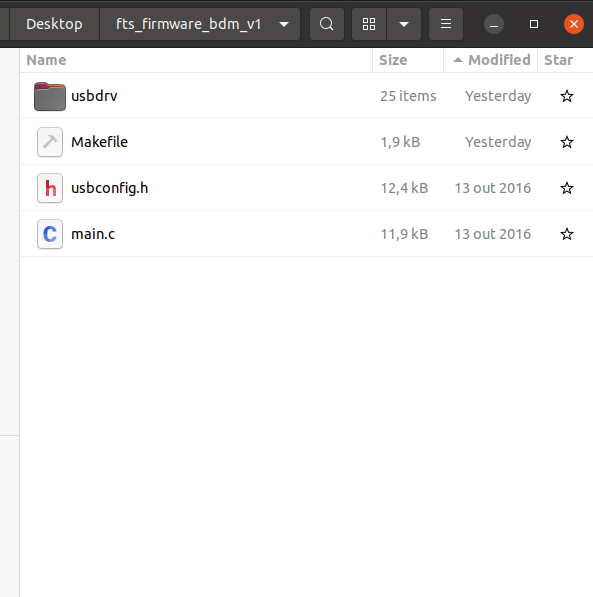
When this did work it was on Linux so try that and run this command:
sudo apt-get install avrdude gcc-avr avr-libc make
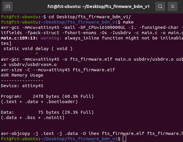
Then:
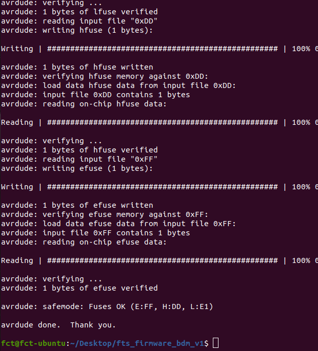
Sudo make flash
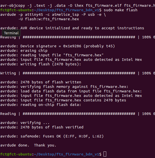
And that should set the fuses and be ready to go.
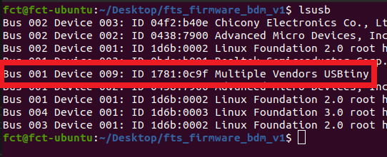
In Linux you can use lsusb to list all USB devices and it’ll be there.
My programmer was a nightmare. It took me 2-3 weeks. I was getting the stupidest errors. With everything I tried. Windows, Linux, my instructors old ISP’s, Atmel ICE’s. Nothing worked until it did once. I got my print-screens and never looked back. Until I had to write all this documentation.