11.5 Input Devices - Part II
Debugging I2C
To declutter the other page I moved most of my 2023 debugging on the XIAO ESP32-C3 boards here.
As the I2C BUS was so unstable I tried to research a lot of possible causes and ways to fix it.
Keep in mind I started doing electronics in 2022 with Fab Academy so a lot of these concepts are above my pay-grade. I’ll try to avoid anything I don’t understand anything of but take all this with a grain of salt and do your own research after.
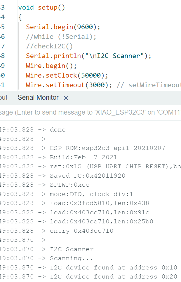
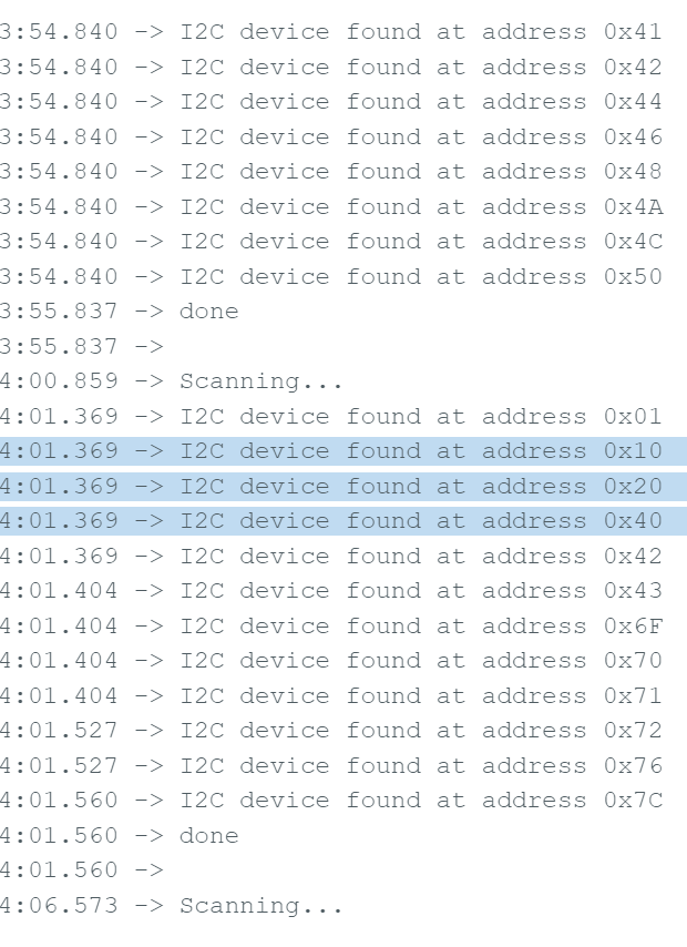
Before I go into my search for answers here’s a look at all the crazy stuff my I2C did:
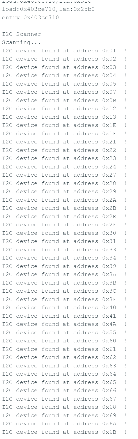
It couldn’t find the device I had plugged in and found phantom devices that didn’t exist.
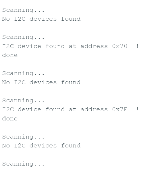
A lot of them.
What…
Is…
This…
It all started midly bad but after a while running even power cycling the whole thing wouldn’t make a difference.
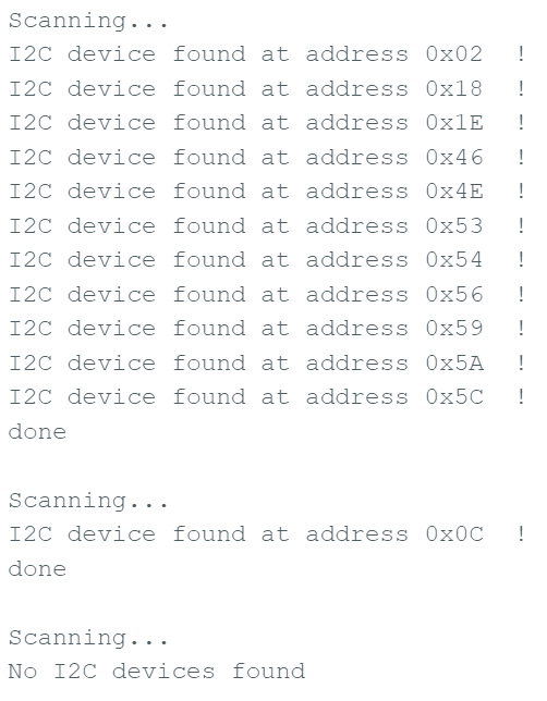
Sometimes it would detect something in ALL addresses.
And I don’t even wanna know.
I2C Pull-up Resistors, Capacitance and Rise-times
The value of a pull-up resistor in I2C isn’t as trivial as it might look at first.
Prof Neil used 5kΩ on the hello boards and from what I could tell they were all running at 5V. On 3.3V logic they start to be a bit too strong and the Rise Time of both SDA and SCL becomes too slow. Wikipedia has a lot of math but just think of it as the time it takes from logic 0 (0V) to logic 1 (3.3-5V) or equivalent. If it’s too slow compared to the bandwidth needed I2C devices might stop recognizing clocks and bytes correctly as bits don’t get to logic 1 in time before the next bit.
This article is pretty good and has some nice .gifs.
When I designed the board I still put 5kΩ in my boards. With a multimeter I also checked if they were doing their jobs:
Which they weren’t. Bad boards or bad soldering, I dunno. I pull them out checked them outside with the multimeter again and while some were ok some I replaced.
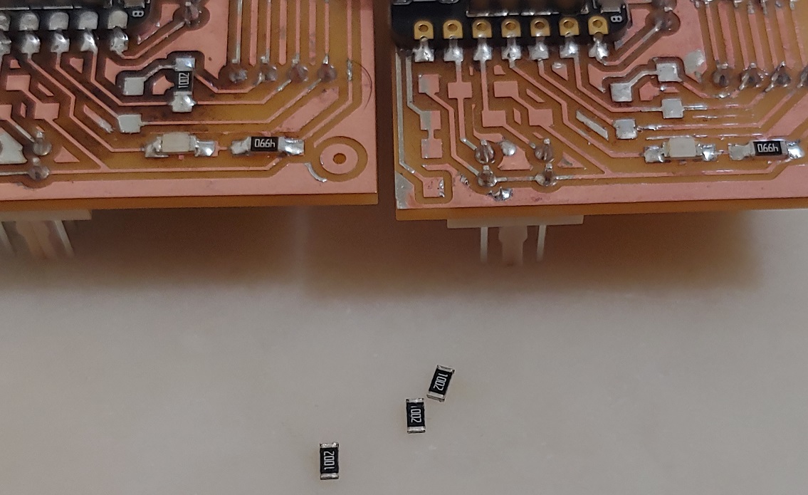
I was in a hurry to test things so I even went back to my boards from last year to salvage some of their pull-ups as they were also 5kΩ.
In the end I had no choice but to just order some for myself and I did. As I further researched the subject I decided to order 2.49kΩ instead due to the lower logic level just in case.
Found a nice .pdf about the math behind picking the pull-up value.
The resistors currently on my board are actually 1kΩ now. And on reddit people were suggesting going even lower, around 900. I had 499Ω ones but I was afraid because at some point the I2C devices just can’t pull down the signal lines. Surely 1k was good enough.
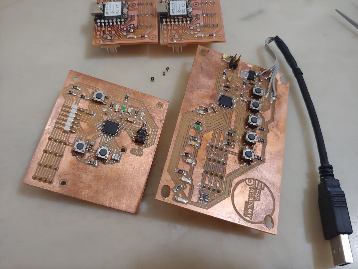
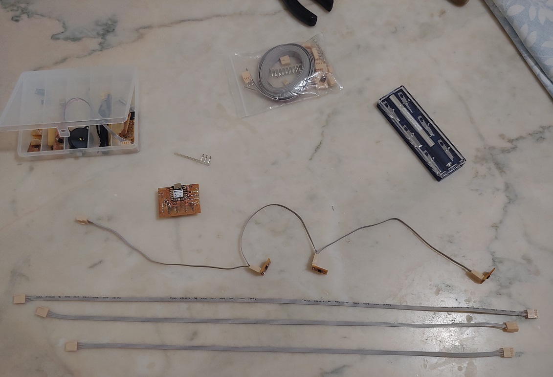
Maybe the single biggest change to my setup was making a daisy chain cable.
Originally I didn’t worry (unknown unknowns, amiright.) about cable lenght. I hadn’t finished the structure of the machine and thought, eh anything will do. I was used to not having to care with other cables for simple or more complex electronics but that I wasn’t aware of the innerworkings of I2C.
The cables I had added a ton of Capacitance which is something I2C is so sensitive to there are limits defined in the standard. If the BUS starts storing the electrical signals as magnetic fields instead of propagating them, we have a problem…
The new cable seemed to stabelize the system a lot. Long enough to maybe get some readings over a few minutes.
Then someone on reddit sent me this Internet Archive link to an old article that showed that changing pull-up values do to rise times. For even faster modes faster Rise Times become critical.
That actually got me thinking, what would happen if instead of speeding things up, I slowed them down?
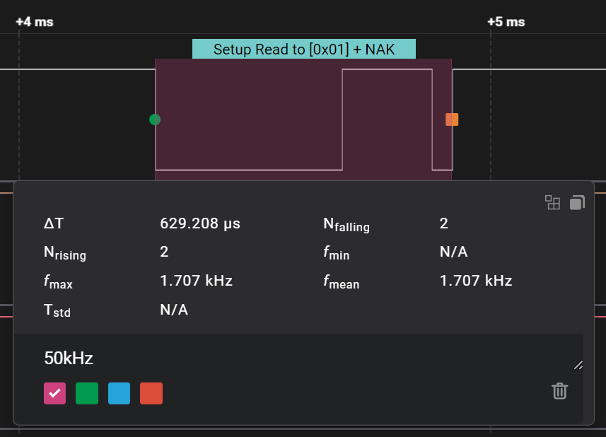
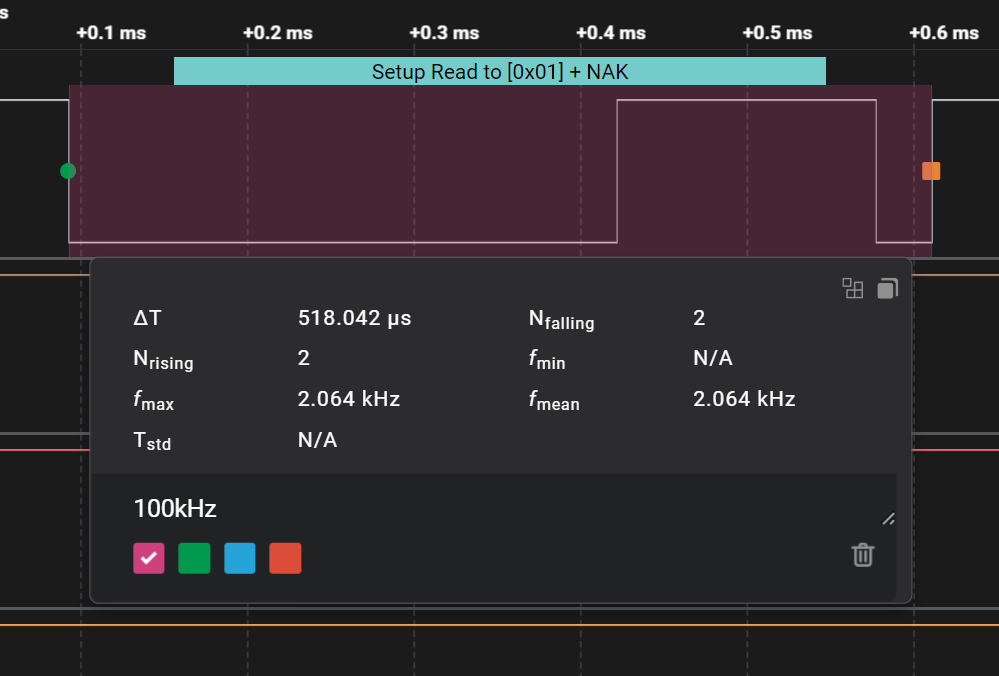
Instead of setting the clock to 100kbit/s I tried 50kbit/s and it actually worked. The AS5600L still recognized the bytes and replied.
It would still break and I’m not sure how much of a differencee it would make but it couldn’t hurt, right?
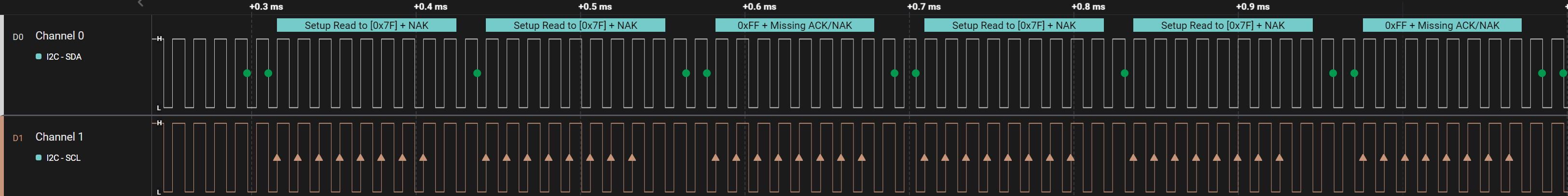
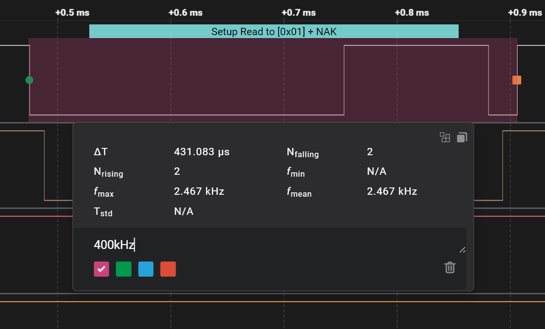
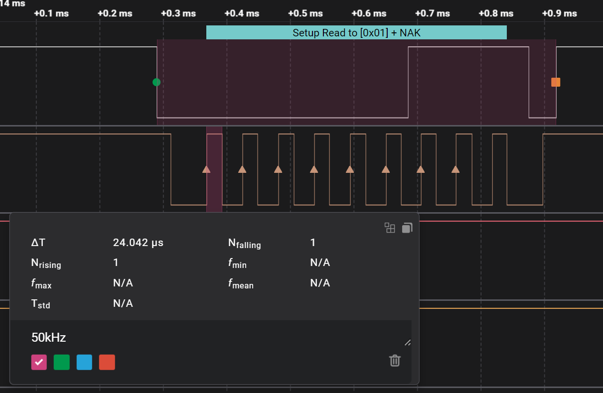
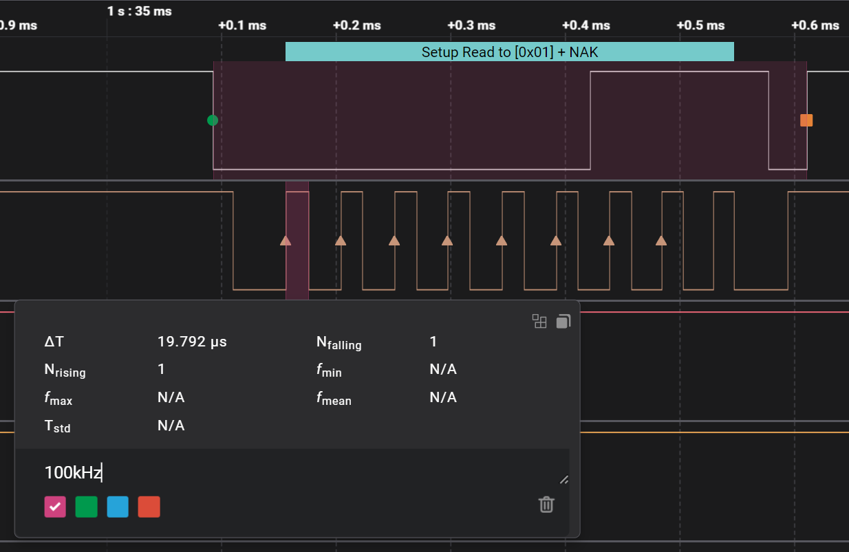
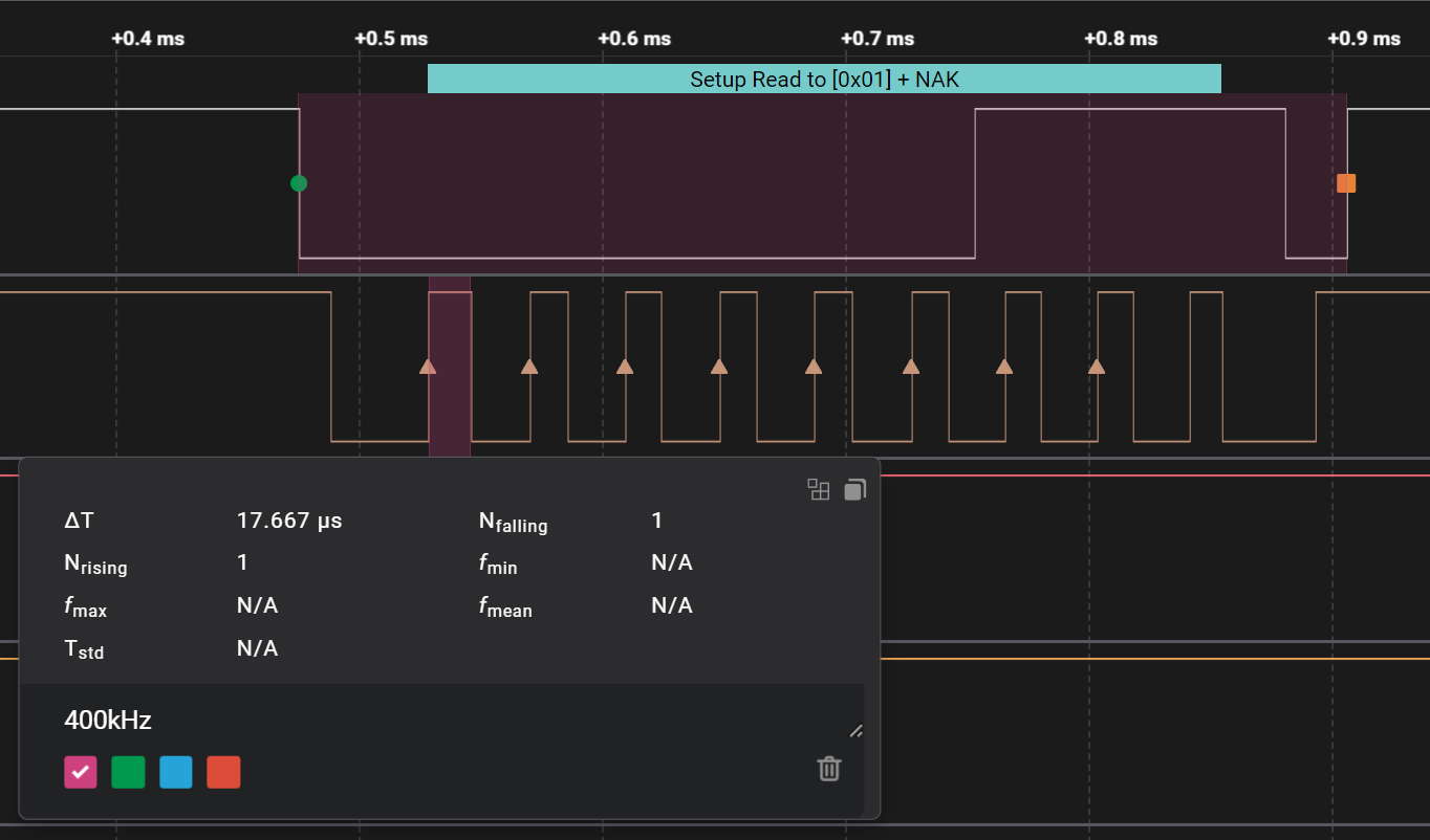
Since I was finding out new things on the Logic 2 software I got carried away looking at byte and clock signal duration in different bandwidths.
Moving on.
I2C Bus Lockup
There’s a condition that can come up after a soft reset of a control device instead of power cycling the whole system or when one device bugs out sending or receiving data. It’s called I2C BUS Lockup and it’s caused by a device keeping the BUS in a busy state indefinetly. Efectively locking out control devices from starting new data transactions.
Let me quote a few paragraphs from this great article on the subject:
To understand how the I2C bus can lock up, it’s helpful to think of things from the perspective of a slave device. The slave must monitor the state of the clock and data signals, and in particular must look out for transitions of either signal which may indicate the start or end of a transaction or the need to clock data in and out. All will be well provided the slave device sees the same series of transitions that the master generates, assuming they conform to the I2C protocol specification.
But if there’s some noise or interference that causes an unwanted extra transition or masks a wanted transition, the slave can get out of step with the master. For example, if the master needs to transfer one byte of data from the slave, the slave is expecting to see a specific number of transitions on the clock signal to clock each bit of the data out (and to provide an acknowledge signal). If a clock edge gets “lost” somehow, the slave device will never finish transferring the data and may end up continuously pulling the data line to an active low state.
Now the master might “think” that the transaction has finished, so won’t issue any more clocks, but the slave “thinks” the transaction is still in progress so will keep the bus in a busy state. While the bus is busy, the master can’t generate any more clock transitions. While there are no clock transitions from the master, the slave won’t let go of the bus.
Another situation where lock-ups might occur is during start-up when i/o signals from the master might have glitches or other unexpected transitions before they are stable. If an I2C slave device is monitoring the bus before the master brings the clock and data lines into the right (passive) state, this can cause the I2C bus to be locked before the master starts the first transaction.
Finally, even if the bus is very well-behaved and doesn’t suffer from noise or glitches, lock-up can occur during software development. Let’s say you’re testing and debugging a system using I2C and your software crashes or hits a breakpoint while an I2C transaction is in mid-flight. If you simply reset the CPU or re-start the software, the I2C slave will never see the end of that transaction so the I2C bus will be locked when the software re-starts.
A good place to start dealing with this is explicitly setting a Wire Timeout value.
I tried looking for details on the reset_on_timeout parameter to understand what it meant by reset though I couldn’t find any specifics. I’ll assume it forces a few SCL clock cyles like the article on Pebblebay mentions.
The delay you use is kind of up to you, the lower it is the better it’ll be at guaranteeing BUS stability but it can then cause software reliability problems if it starts resetting the BUS too frequently. Especially if some devices need more time to process commands than others. Say for example instead of a small sensor we’re trying to establish a comunication between 2x micro-controllers that might involve complex computations or even waiting for other devices connected with different protocols.
For some reason the Wire library for ESP32 micro-controllers uses a different syntax. It’s just setTimeOut() and doesn’t have a bool reset parameter. I couldn’t decifer if it did it automatically or not.
After this I turned to the I2C registers of the ESP32. I wondered if there was Busy register.
I tried looking for it in the regular ESP32-C3 datasheet but couldn’t find it.
Eventually I discovered the ESP32-C3 Technical Manual and it had what I was looking for.
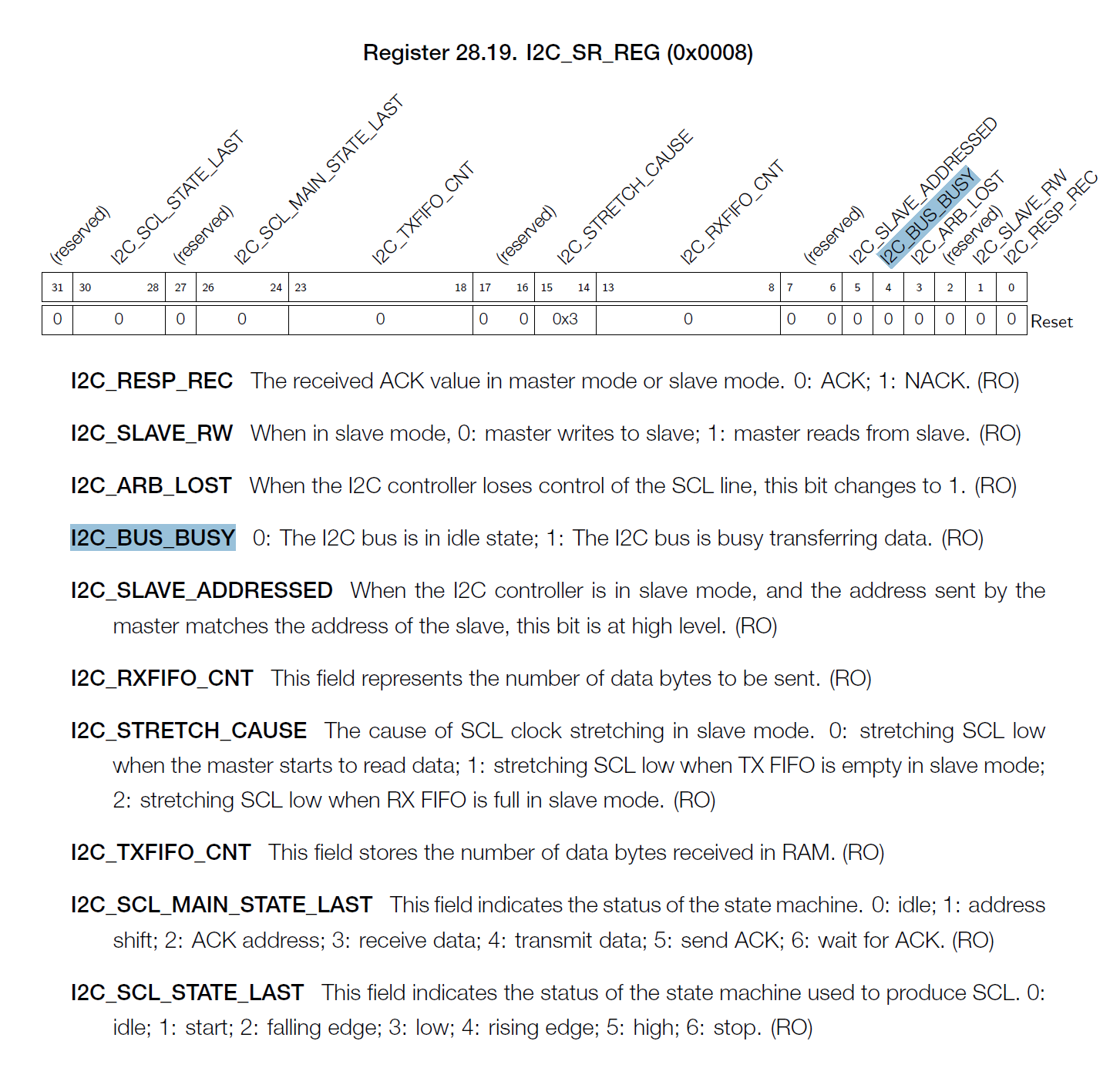
The bit I was looking for was called I2C_BUS_BUSY inside the 2C_SR_REG register.
Problem was, I couldn’t find mentions to it in the ESP32 core...............
I was using the web-gui search on GitHub. It sucks. Someone on reddit used a linux command on a local copy:
$ grep -R I2C_SR_REG ~/.arduino15/packages/esp32/ 2>/dev/null
That found the mentions:
/home/.../.arduino15/packages/esp32/hardware/esp32/2.0.5/tools/sdk/esp32s3/include/soc/esp32s3/include/soc/i2c_reg.h:/** I2C_SR_REG register
/home/.../.arduino15/packages/esp32/hardware/esp32/2.0.5/tools/sdk/esp32s3/include/soc/esp32s3/include/soc/i2c_reg.h:#define I2C_SR_REG (DR_REG_I2C_BASE + 0x8)
/home/.../.arduino15/packages/esp32/hardware/esp32/2.0.5/tools/sdk/esp32/include/soc/esp32/include/soc/i2c_reg.h:#define I2C_SR_REG(i) (REG_I2C_BASE(i) + 0x0008)
/home/.../.arduino15/packages/esp32/hardware/esp32/2.0.5/tools/sdk/esp32s2/include/soc/esp32s2/include/soc/i2c_reg.h:#define I2C_SR_REG(i) (REG_I2C_BASE(i) + 0x0008)
/home/.../.arduino15/packages/esp32/hardware/esp32/2.0.5/tools/sdk/esp32c3/include/soc/esp32c3/include/soc/i2c_reg.h:#define I2C_SR_REG(i) (REG_I2C_BASE(i) + 0x8)
With a file name and path it was easy to find the mentions.
There’s a main #define I2C_SR_REG(i) (REG_I2C_BASE(i) + 0x0008) for the register followed by the individual bit contents and finally I2C_BUS_BUSY bit location data:
/* I2C_BUS_BUSY : RO ;bitpos:[4] ;default: 1'b0 ; */
/*description: 1:I2C bus is busy transferring data. 0:I2C bus is in idle state.*/
#define I2C_BUS_BUSY  (BIT(4))
#define I2C_BUS_BUSY_M  (BIT(4))
#define I2C_BUS_BUSY_V  0x1
#define I2C_BUS_BUSY_S  4
When I tried assigning the register to a variable I got an Undeclared error and was getting confused. Eventually I found a file that should work but what mattered to me was that it had something I didn’t think off. Just like when we want to manipulate pin registers we have to include the .IO file, if I want to interact with other registers I should’ve thought I’d need to include the a specific registers file. To talk to 2C_SR_REG I needed #include <soc/i2c_reg.h>.
After getting that sorted I figured out 2 ways of calling for the same data:
bool busyStatus = I2C_SR_REG(I2C_BUS_BUSY_S); // Asks directly for the i2c busy status register with I2C_BUS_BUSY_S

bool busyStatus = bitRead(I2C_BUS_BUSY, 4); // I2C_BUS_BUSY seemed to return the bitmask so a bitRead is necessary.
Alternative I2C Libraries
Prof. Neil told me to try out other libraries or even his own bit-banged code.
From what I could find online even the libraries can cause problems between micro-controllers so might as well debug for that.
I found 3x more I2C libraries: SoftWire, SoftwareWire and SBWire.
Picked Softwire just because it was the one with the most recent update.
I ran 2x different I2C Scans, one with the Arduino library:
#include <Arduino.h>
#include <Wire.h>

void setup(){
  Serial.begin(9600);
  //while (!Serial); // This line doesn't allow the code to run until it's connected to a computer and a serial COM port is open.
  Serial.println("\nI2C Scanner");
  Wire.begin();
  Wire.setClock(50000); // Bandwidth slowed below 100kbit/s standard
  Wire.setTimeout(200); // setWireTimeout has a different syntax on the ESP32. Only accepts an int as parameter, no bool for a forced reset attempt? Automatic?
}

void loop(){
  byte error, address;
  int nDevices;
  Serial.println("Scanning...");
  nDevices = 0;
  for(address = 1; address < 127; address++ ){
  Wire.beginTransmission(address);
  error = Wire.endTransmission();
  if (error == 0){
    Serial.print("I2C device found at address 0x");
    if (address<16)
      Serial.print("0");
    Serial.print(address,HEX);
    Serial.println("  !");
    nDevices++;
  }
  else if (error==4){
    Serial.print("Unknown error at address 0x");
    if (address<16)
      Serial.print("0");
    Serial.println(address,HEX);
    }
  }
  if (nDevices == 0){
    Serial.println("No I2C devices found\n");
  }
  else{
    Serial.println("done\n");
  }
  delay(5000);
}
And one using Softwire:
#include <SoftWire.h>
#include <AsyncDelay.h> // SoftWire install says we need this one too

SoftWire WIRE(SDA, SCL); // SDA and SCl seem use the pre-defined hadrware pins. To use custom pins just use their numbers

void setup(void){
#if F_CPU >= 12000000UL
  Serial.begin(115200);
#else
  Serial.begin(9600);
#endif
  WIRE.setTimeout_ms(40);
  WIRE.begin();
  WIRE.setClock(50000);
  // Set how long we are willing to wait for a device to respond
  WIRE.setTimeout_ms(200);
}

void loop(void){
  const uint8_t firstAddr = 7; //
  const uint8_t lastAddr = 0x7F;
  Serial.println();
  Serial.print("Interrogating all addresses in range 0x");
  Serial.print(firstAddr, HEX);
  Serial.print(" - 0x");
  Serial.print(lastAddr, HEX);
  Serial.println(" (inclusive) ...");
  for (uint8_t addr = firstAddr; addr <= lastAddr; addr++) {
    delayMicroseconds(50);

    uint8_t startResult = WIRE.llStart((addr << 1) + 1); // Signal a read
    WIRE.stop();
    if (startResult == 0) {
      Serial.print("\rDevice found at 0x");
      Serial.println(addr, HEX);
      Serial.flush();
    }
    delay(10);
  }
  Serial.println("Finished");
  delay(5000);
}
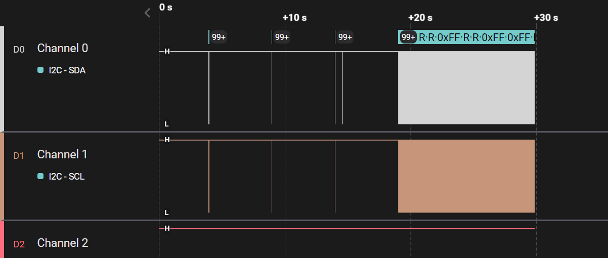
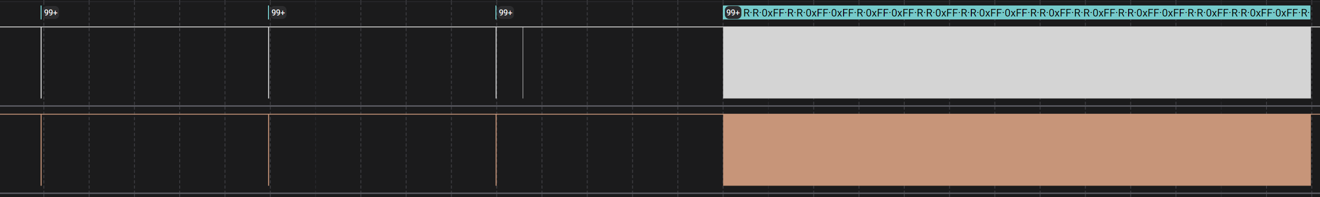
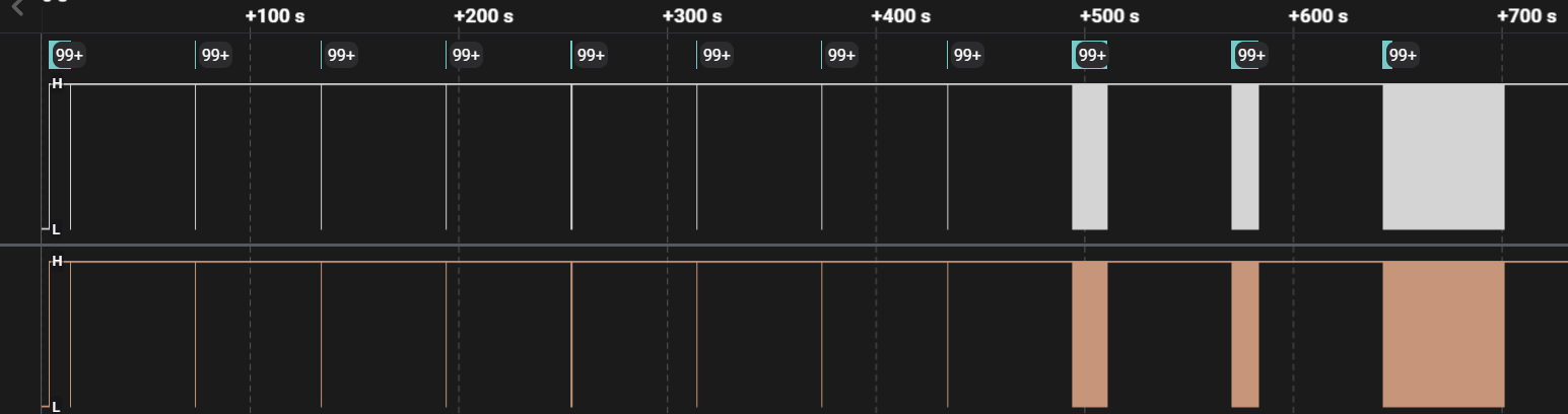
Then I turned on timestamps in the Serial Monitor and let them run until they broke.
Both broke after close to the 8min mark.
For some reason there’s no Select All option on the Arduino IDE serial monitor so I manualy copy-pasted the contents into 2x log files: Log_SerialMonitor-HardwareWireScan.txt and Log_SerialMonitor-SoftWireScan.txt.
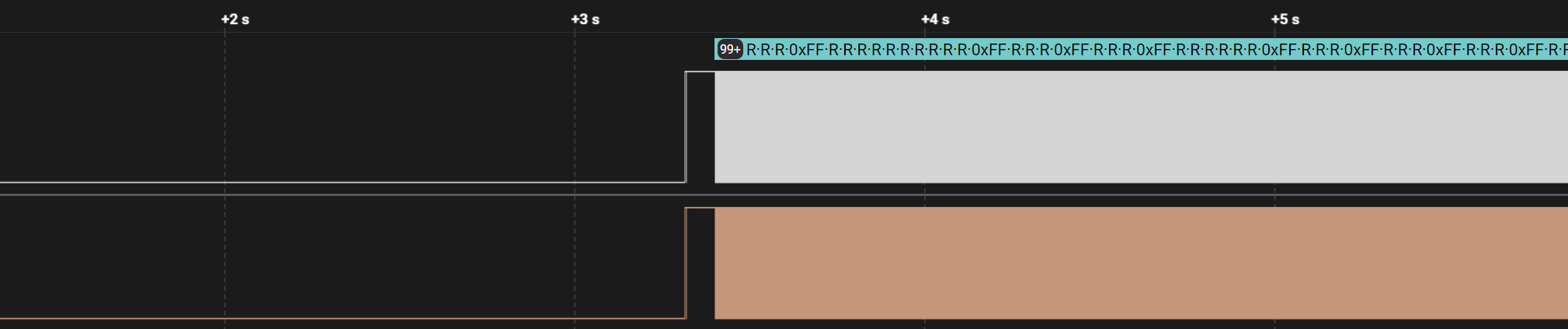
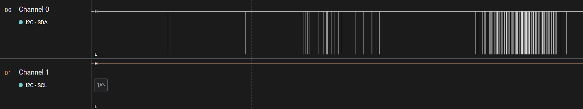
If you open them in a code editor that has an overview viewport like Sublime it’s easy to see when the message pattern brakes when the I2C BUS stops working properly.
Up to know the options were mostly external to the motherboard hardware and layout. I didn’t make another physical board revision but if I did I could also try another setting 2x different pins. For all I know the default SDA and SCL pins could have some weird bug. Even the SoftWire library supports non-standard pins.
Power Rail Noise - Decoupling Capacitors
Prof. Neil said I had to connect my board to an Oscilloscope to check for Noise. So I did and quickly noticed I had no idea what I was looking for…
Should have taken a few prints of the oscilloscope as it didn’t feel very noisy but maybe I could try and figure it out one day. I need more experience with circuits that misbehave so I can have a better understanding of how noise and interference manifest themselves.
Prof. Neil has a book and lectures a class on the subject but all the math makes my head hurt.
Decoupling Capacitors play an important part in dealing with power rail noise so they came up a lot in my research.
The gist is that the power loop between a device, within a pcb or connected by cables, has inherant Inductance and Capacitance related noise. Whenever a device draws current from the power supply there will also be a noticeable voltage drop that will affect everything connected to each power loop.
The role of Decoupling Capacitors isn’t to fix the noise the power loop has; it’s to quite literally and figuratively short the power loop and just make a shorter loop with less noise. Decoupling the chip from the bigger loop’s impedence noise. And that’s why we always have to put them as close to the power pins as possible. The shorter the loop the less noise will reach the chip. Some chips have integrated capacitors specifically for this. And the package of the capacitor also plays a role. A small SMD capacitor might do a better job than a much larger through-hole one at the same distance because of the long legs.
These are the videos that helped me visualize the thing:
What Decoupling Capacitor Value To Use And Where To Place Them with Eric Bogatin
Power Distribution Tips To Control SI, EMI and Noise with Rick Hartley
These Eric Bogatin and Rick Hartley fellas do seem to know their stuff so you can find plenty of videos of them around the internet to binge. A lot of their advice is related to multi-layer boards but dream big right? xD
There’s also this Eric Bogatin clip on Altium’s Academy Youtube channel that’s nice. Although it goes over part of the other one before.
Return Path
Time to get funky. I can’t tell you how much this interferes with what we do… Given that we’re mostly working with 1 layer boards for now it’s for the best to do everything in our power to minimize it’s effects on our boards.
This gets confusing quickly… Thankfully there seems to be a plethora of resources on this topic. Maybe because of how important it is.
The TL;DR is simple: we’ve all heard that electricity likes to follow the path of least resistance but that’s not always the case. As we move up in bandwidth; as we move down in rise-times; electric signals start acting weird. The magnetic fields they generate start to want to follow a different path. High-speed signals follow the path of least Impedence, not the path of least resistance…
Lets start with these 2 images I got from an article on Altium’s website. Examples tend to assume we have a solid ground plane. Because why would we not… Imagine how bad this can get in single sided boards with our weird beginners routing. Copper pouring ground probably helps.
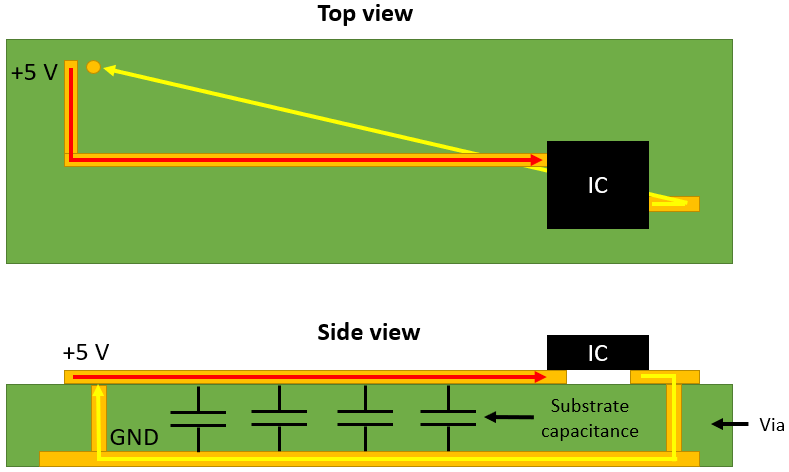
That was regular slow signals. Now this is what fast signals actually want to do:
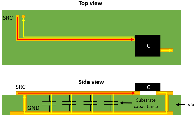
Don’t ask me how exactly this affects the signal but I’m sure it’s bad.
Once you start thinking of electricity with magnetic fields it gets a bit easier. This gif I got from this page on AllAboutCircuits is a good start:
Derek Muller made a couple of videos on this that might help:
That was the first one and it kinda broke the youtube science comunity for a bit so he had to make another one (even has a Rick Hartley cameo):
If you still want to watch one more video on that Mehdi a.k.a. ElectroBOOM made a video of 2x conversations he had with Derek expanding on the topic:
Back to return paths. This video is pretty succinct.
I found a nice graphical example on this page that’s actually referencing this article:
It goes for the smallest path first but as frequency goes up it starts following the signal trace.
So you might be wondering what qualifies as “high frequency”. I couldn’t find any concrete answer. Prof. Neil replied High frequency is defined by the wavelength vs the system size. Honestly I’d’ve prefered just a number to have an idea lol
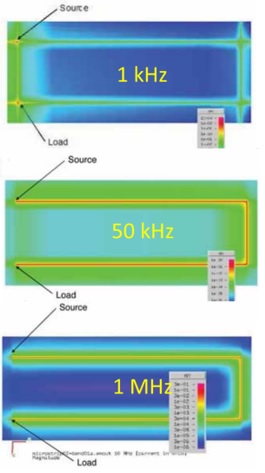
This image also shows the effects although they seem to ramp up slower here:
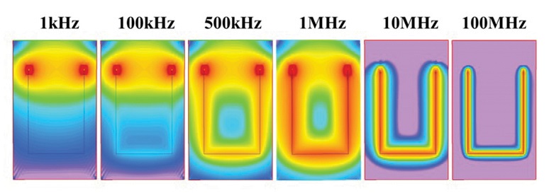
While that other low res image already has a clear return path under the trace at 50KHz a lot of places I found online seemed to suggest it starts becoming a problem between 50-100KHz.
The website I got this last image from mentions frequencies close to another website I found:
Low Frequencies (1 KHz - 100 KHz)
Pulses propagating at low frequencies return the current through the path of least resistance (like DC). Because of the weak parasitic capacitance, this current gets inductively induced as a loop around the circuit. So it creates a straight path between the ground and the source.
Medium-High Frequencies (500 KHz - 1 MHz)
The current return splits between the two paths if transmitting the signal between the low and high frequencies. Some electrical current goes via a straight line back to the source, while the rest travels under the signal trace.
High Frequencies (>10 MHz)
Once you transmit high-frequency signals over 10 MHz, parasitic capacitance between the source and reference plane will dominate the circuit. So the return current path will form underneath the upper signal trace because it is the path of minimal reactance.
So for now I don’t have a definitive number. Fast Mode Plus I2C with it’s 1MHz bandwidth can surely already be affected.
This video shows more detail:
And this one does a deep dive.
If you want more reading material I also found these 2x Texas Instruments guideline .pdfs:
And
And this one my search engine found inside NASA’s website so it must be at least ok?
Have I read all of those? Not yet, but I plan to. Maybe not the USB Hub one. I’m not expecting to deal with USB 3.0 anytime soon.
Crosstalk and Reflections
This last bit is starting to get into the really far fringes of what might become a problem for anyone doing 1-layer boards in Fab Academy but it might be good knowing they are a thing.
As a nice segway from return paths this video shows a few simulations of how bad return paths can cause Crosstalk even between fairly spaced traces:
Crosstalk is one of many problems that can affect our Signal Integrity. One of the basic objectives of a PCB designer has to be that a must signal exit a channel the same as when it went in.
Here’s a quick overview of Signal Integrity challenges:
PS: Prof. Neil also mentioned Eye Diagrams but I didn’t look into them. They seem to need a fancyish oscilloscope.
Making sure what ever is at the end interprets the message correctly comes later.
Something else that can cause bad crosstalk issues are Parallel traces. You know, the ones that look really nice and orderly…
A topic Eric Bogotin mentions in that clip are Signal Reflections. Since it’s established that electricity involves magnetic fields, we know it’ll involve electro magnetic waves… Waves like to bounce around and they love to bump around in copper. In long or sensitive transmission lines reflections need to be addressed with special Termination device to make sure there are no unwanted waves bouncing around.
Reflections also lead to the development of a really neat device called Time-domain Reflectometer that can sense the failure mode and estimate it’s distance from a test signal it injects.
Funny enough I actually saw one in action a few days before learning about the term and technology behind it. We were having problems with the internet connection and the team sent by the service provider had the Fiber-Optic version of a Reflectometer. Our connection has a few km’s of fiber between the house and the ISP’s OLT and unlike other times where they had to check every splice along the line this time they just hooked the thing up and in couple of minutes they knew there was a problem around 50m away from the exit point in the house. It was amazing.
If you think you’ll make pcb’s with more than 1 layer you’ll probably want to watch these next ones.
This one mentions crosstalk generated from vias and moving signals from one layer to another.
And this one is just general layer stack up.
From what I got of a few clips I saw that touch on the subject, for low number of layers like between 2 and 8 the best layout is SIGNAL/POWER + GND and then just alternating that.
SIGNAL / POWER
+
GROUND
+
SIGNAL / POWER
+
GROUND
+
+SIGNAL / POWER
+
GROUND
+
+SIGNAL / POWER
+
GROUND
This only get more complicated when there’s a lot of EMI to deal with or different voltages being routed that might make it easier to have power planes too. But those can also cause problems as mentioned in the via crosstalk video. And other places.
Here’s one last clip of Rick Hartley talking about controlling Noise, Interference and EMI:
Optimizations
Still here? Here are some easter-eggs:
Optimizing pcb’s for fabrication:
Trying to solve manufacturing problems before they become problems.
And finally making of a 4-layer PCB at the Eurocircuits Board House: