5. Embedded programming
Editor’s note 2023
This was previously assignment 9.
Group Assignment - Comparing MCU Architectures
| MCU Specs | AtTiny44 | AtMega328p | SAMD21E18 | ESP32-C3 |
|---|---|---|---|---|
| CPU Speed | 20 Mhz | 20 Mhz | 48 Mhz | 160 Mhz |
| Flash Storage | 4 KBytes | 32 KBytes | 256 KBytes | 4 MBytes |
| RAM | 256 Bytes | 1024 Bytes | 32 KBytes | 400 KBytes |
| Timmers-Counters | 1x 8 bit, 1x 16 bit | 2x 8 bit, 1x 16 bit | 3x 16 bit + 1x Real Time | 3x 54 bit + 4x Watchdog |
| Pin Count | 14 | 32 | 32 | 32 |
| Analog Pins | 12 | 8 | 10 | 6 |
| SPI - I2C - I2S | 1 - 1 - 0 | 1 - 1 - 0 | Up to 4 - 1 | 3 - 2 - 1 |
| USB | No | No | Yes | Yes |
| Programming | SPI | SPI | SWD/USB/JTAG | USB/JTAG |
| Wireless Coms | No | No | No | Wifi & Bluetooth |
| Max Voltage | 5.5 V | 5.5 V | 3.8 V | 3.6 V |
All MCU’s have a similar day to day work flow of getting the appropriate programmer hardware to interface with the MCU and installing the corresponding Core to Arduino IDE. The main differences are the SAMD chips that first need EDBG to burn a specific Bootloader so that programming over USB becomes active and the ESP32-C3 is regularly integrated within a module that already has an integrated Programmer and a usable USB connection out of the box.
AtMega 328p - Arduino Uno R3
I have an Arduino Uno R3 SMD that’s a good place to start. It has an integrated programmer and sketches can be uploaded through USB out of the box.
You can read more about them here.
Download and run Arduino IDE then go find and open the Blink Example.
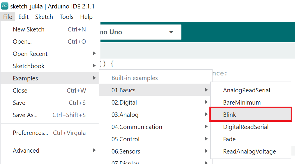
The code has a predefined LED_BUILTIN which is just like a shortcut for PIN13 on the Arduino Uno.
void setup() {
  pinMode(LED_BUILTIN, OUTPUT); // initialize digital pin LED_BUILTIN as an output.
}

// the loop function runs over and over again forever
void loop() {
  digitalWrite(LED_BUILTIN, HIGH);  // turn the LED on (HIGH is the voltage level)
  delay(1000);                      // wait for a second
  digitalWrite(LED_BUILTIN, LOW);   // turn the LED off by making the voltage LOW
  delay(1000);                      // wait for a second
}
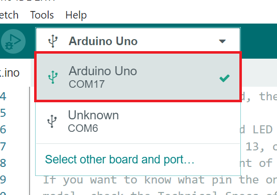
Select the COM port for the device you want.
Compiling will let you know if there are any major issues. If you have the wrong board selected compiling can fail from different Core settings between micro-controllers.

Hit Upload.
Blinkin’ every 1s.
SAMD21 - Adafruit Feather M0 Adalogger
Also bought a Feather Adalogger a while back to try and interact with the SD card when I have some time. Coincidentally the Adalogger also has an LED_BUILTIN defined. The example sketch will run the same on both boards.
You can read more about the Adalogger here.
Unlike the Uno that has everything it needs included within Arduino IDE, the Feather has some extra steps to install the MCU Core. Follow this tutorial on Adafruit’s website. I do a deepdive on my individual assignment documentation.
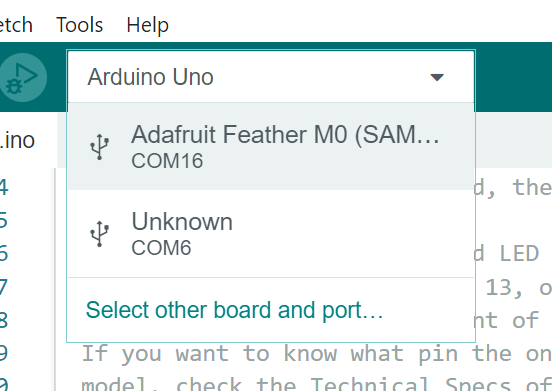
Same deal, after selecting the board pick the corresponding COM port.
Compiling also gives you an idea of used resources, especially memory.

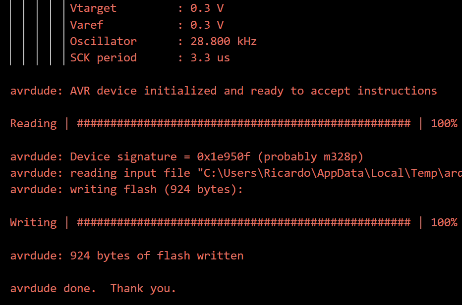
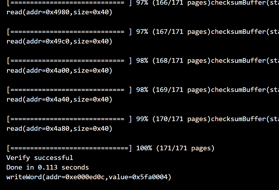
Uploading also generates different text between different architectures. Each one has individual protocols for verification after upload.
Some more blinking action.
Individual Assignment - DataSheets
Datasheets are a really good reminder that as much as we know, we know very little.
I looked at the TinyX4 family.
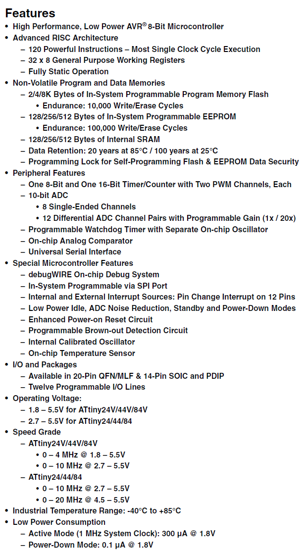
Datasheets always have a nice marketing table of included features.
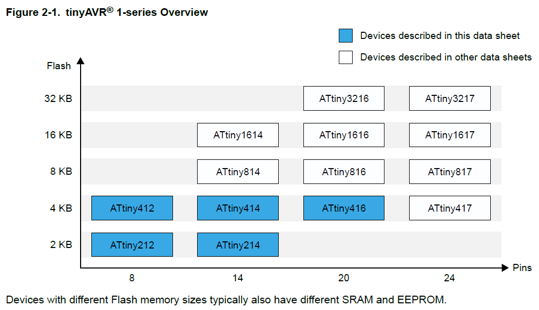
Some of them are nice enough to have tables to diferentiate between the models
Others like the X4 family like to leave them within written sentences which can make finding them harder.

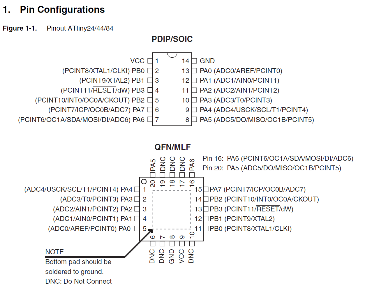
One of the most basic informations we can get out of a datasheet are the package pinouts. What pin supports what function.
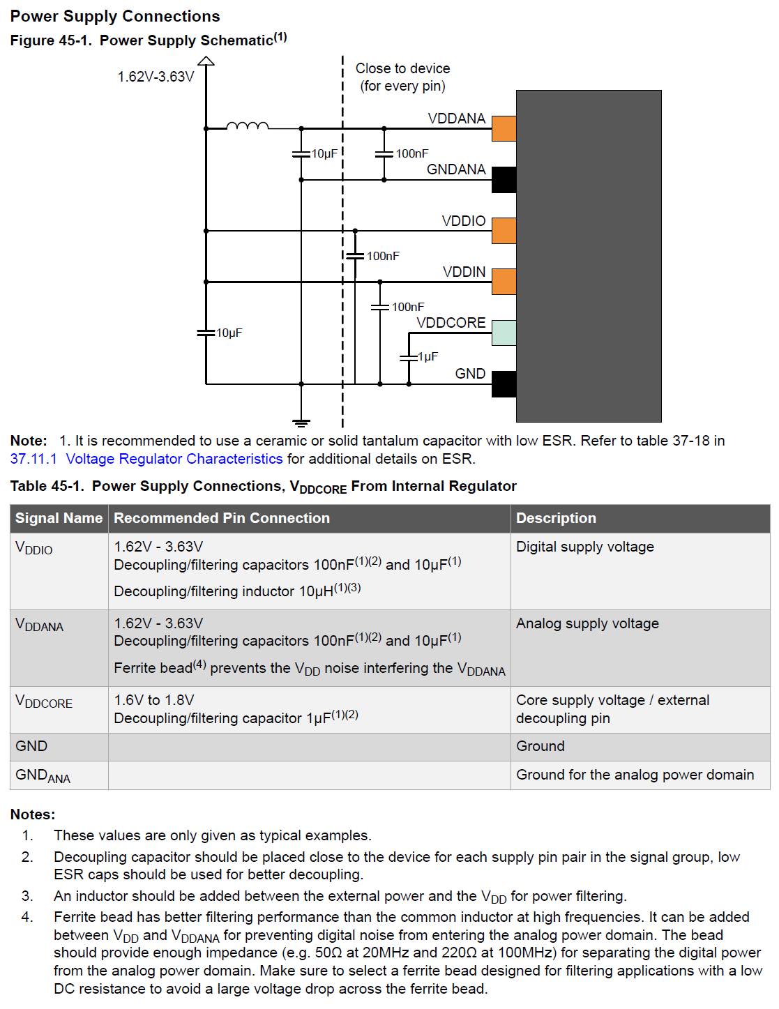
In some cases there are also mentions to special requirements needed to get the MCU’s in working condition, like strapping pins or in the case of the SAMD21 details on the power supply components.
Individual Assignment - Codin’
Picking an IDE (Integrated development environment) software
There are plenty of options out there…
As a beginner I ended up sticking with Arduino IDE.
![]()
I wanted to try Microchip Studio (previously known as Atmel Studio) since they’re the ones making microcontrollers. And unistalled it about 5mins later.
![]()
Download through here but be warned it’s very overwhelming… Too much stuff going on… Probably a decent choice eventually once we know what we’re doing.
From my research, something in between for slighly more knowledgeable users there’s Eclipse.
![]()
It seems like a good middle ground to move beyond Arduino IDE’s capabilities and I might give it a more serious inspection sooner rather than later.
I’ve also read some good things about Microsoft’s Visual Studio, specifically a plugin called PlatformIO.
Once I’m ready to move on from Arduino IDE I’ll be comparing Eclipse and Visual Studio/PlatformIO to see which one I like best.
Getting Arduino IDE ready
Arduino has a nice overview with all the basics.
Editor’s note 2023
Last year this assignment came after electronics production and design so this part of the documentation was written asssuming I was going to program a board I already designed and made with an AtTiny44. 1st step is getting the AtTiny core.
MCU Cores
Cores are where information is stored that will allow your IDE to get to know the micro-controller you want to use. For the Tiny4x Get It Here. Be aware that for more recent and not so tiny Tiny’s there’s another Core called megaTinyCore
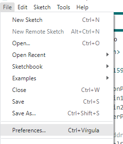
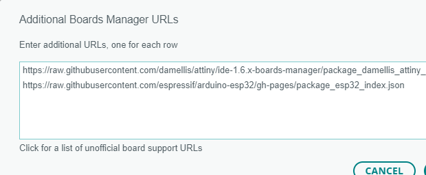
Open Arduino IDE’s preferences.
You can paste it directly if it’s the first but after that click the button to open a larger modal box.
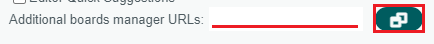
Paste this into it’s own line.
https://raw.githubusercontent.com/damellis/attiny/ide-1.6.x-boards-manager/package_damellis_attiny_index.json
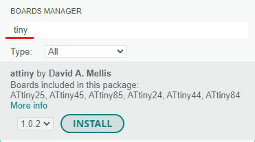
After that you’ll need to actually download and install the core files from the Board Manager.
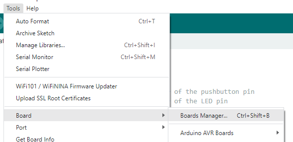
The UI changed quite a bit from Arduino IDE 1.8 to 2.0 but you’ll figure it out.
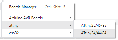
Pick the architecture/model.
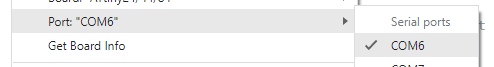
COM Port.
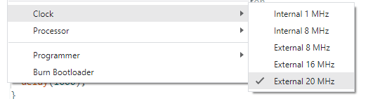
Cores usually have more advanced settings for either hardware config or debugging. In this case my board has an external clock, picking the wrong one messes with timmings.
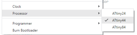
Make sure to pick the correct processor. Compiling might fail or the program won’t run as expected.
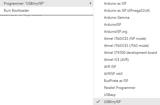
For loading programs and a bootloader a programmer is needed. It can be a tinyISP like the FabTinyISP we had to make before. Sometimes the core automatically knows what programer it needs like for the Arduino Uno or ESP32 modules.
A bootloader is a special bit of code that readies the hardware to performe specific functions, in our case it usually prepares the MCU’s to run our programs. They can automatically setup registers and fuses to make sure things work as expected. For example in the ESP32 the Arduino Bootloader can remove the need to click the “boot” button everytime you want to upload a program. Makes prototyping a lot easier.
Sparkfun has a nice page on using the Arduino bootloader.
Using C
Programming MCU’s is generally done with C and C++. Some micro-controllers these days accept MicroPython. From the name I can tell you that it’s related to regular Python but I don’t know enough about either to tell you the differences. Neil recomended I try CircuitPython which seems to be a re-write of MicroPython targeting beginners so I’ll definetly give it a look once I graduate.
Arduino sketchs are built around C with 2 special functions called Setup() and Main(). With Setup() running once and Loop() running indefinetly. There are also some other predefined general purpose functions to help interact with devices that you can read more about here. Compiling fails if Setup() and Loop() as missing. You can read more about the Arduino loop here.
Everyone starts with a basic Blink sketch.
// the setup function runs once when you press reset or power the board
void setup() {
  pinMode(LED_BUILTIN, OUTPUT);// initialize digital pin LED_BUILTIN as an output.
}

// the loop function runs over and over forever
void loop() {
  digitalWrite(LED_BUILTIN, HIGH);  // turn the LED on (HIGH is the voltage level)
  delay(1000);                      // wait for a second
  digitalWrite(LED_BUILTIN, LOW);   // turn the LED off by making the voltage LOW
  delay(1000);                      // wait for a second
}
Setup() runs only once. It’s used to prepare things for the code, actions and reactions that will be run indefinetly on the Loop() function.
pinMode tells the micro-controller that a certain pin is either an input or output. LED_BUILTIN is just an Arduino IDE for a specific pin on Arduino boards that have a built-in LED.
Stuff inside Setup() isn’t set in stone, they’re just an initial state for code in Loop() that can have pre-requirements. Code in Loop() can overwrite actions set in Setup(), like a pin can be changed from input to output and vice-versa on the fly.
The comments (the text after the //) on that bit of code are pretty self-explainatory. Turn a writting a pin HIGH means it tells the micro-controller to bump the voltage on said pin up to max voltage. LOW pulls it down to 0V. Each change is has a delay in between of 1000ms.
Next come Pinouts. Specifically the one about the Tiny44 I used.
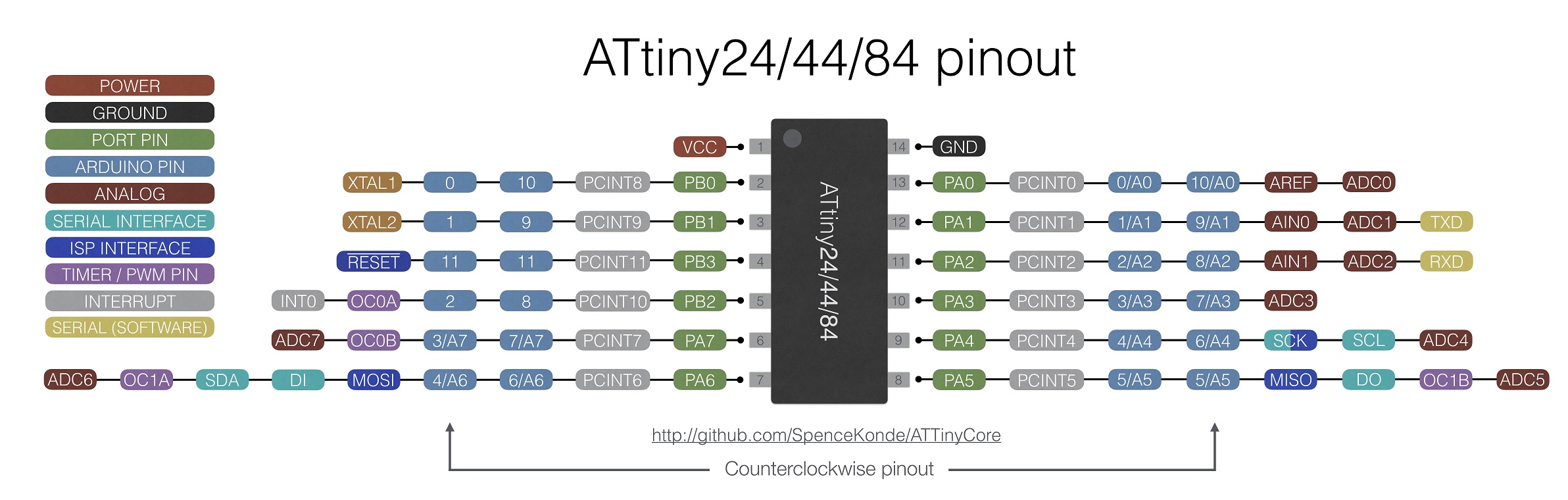
Pinouts are where we can both see the function of a pin and how the pins are named so we can use the correct syntax when addressing them. In my case I connected the LED to pin PA2 so instead of LED_BUILTIN I have to create a constant to store that “name”.
Arduino calls PA2 just 2. PA2 is it’s hardwired name and it’s unimportant now.
const byte ledPin1 = 2; // Constant to store the pin number.
Storing the pin name in a constant also helps reusing or rewritting the code later for a different board. When there’s code already written, sometimes we can just skip changing the pin name and just redefine them. Like:
#define LED_BUILTIN 2 // Redefines LED_BUILTIN to point to pin 2.
Something else we can tweak in the example code that will be come in handy in the future is making our own function. Understanding the C function() syntax can help clean up code once we start building more complex programs.
Functions can have data input and output. The void in Setup and Loop means no data is returned from running that fuction. If the function is returning data put the data type before the function name. Input parameters go inside the parenthesis like (parameter1, etc).
The blink example can have a blinkOnce() function. In this is a bit pointless but we need to run a code snippet in multiple places by just call the function instead of pasting the same code over and over again. Also make’s updating algorithms easier since we don’t have to find all copies.
const byte ledPin =  2;      // the number of the LED pin

void blinkOnce(){
  digitalWrite(ledPin, HIGH);
  delay(1000);
  digitalWrite(ledPin, LOW);
  delay(1000);
}

void setup() {
  pinMode(ledPin, OUTPUT);
}

void loop() {
  blinkOnce();
}
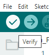
Verify to make sure we didn’t screw up anything, including MCU settings.
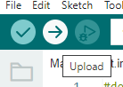
And upload.
Editor’s note 2023
The Blink example documentation used to belong to the Electronics Design assignment to test that our new boards worked.
Here’s the code I actually wrote for the original embedded programming assignment:
// constants won't change. They're used here to set pin numbers:
const byte buttonPin = 8;     // the number of the pushbutton pin
const byte ledPin1 =  2;      // the number of the LED pin
const byte ledPin2 =  3;      // the number of the LED pin
const byte buzzerPin =  7;      // the number of the LED pin

// variables will change:
byte buttonState;          // variable for reading the pushbutton status
byte buttonCounter =1;       // variable for counting button presses
byte debugCycle =0;
byte lastButtonState = HIGH; // this lastButtonState is determined by the resting state of the button. Which is related to the use of either a pull-up or pull-down resistor. But that's a story for Electronics Design week.

void beep(){
  digitalWrite(buzzerPin, HIGH);  // Turn pin HIGH to Activates the buzzer, waits for 30ms and turns it back to off.
  delay(30);
  digitalWrite(buzzerPin, LOW);
}

void setup() {

  pinMode(buttonPin, INPUT); // initialize the pushbutton pin as an input:
  pinMode(ledPin1, OUTPUT); // initialize the LED pin as an output:
  pinMode(ledPin2, OUTPUT); // initialize the LED pin as an output:
  pinMode(buzzerPin, OUTPUT); // initialize the LED pin as an output:
}

void loop() {
  // read the state of the pushbutton value:
delay(25); //debounce
buttonState = digitalRead(buttonPin);   // reads the button state
  if (buttonState != lastButtonState){  // compares it to the last state
    if (buttonState == LOW){    // If it changed from HIGH to LOW.
      switch (buttonCounter){   // Run a case depending on the stored buttonCounter value
        case 0:
          buttonCounter++;
          digitalWrite(ledPin1, LOW);
          digitalWrite(ledPin2, LOW);
          beep();
          break;
        case 1:
          buttonCounter++;
          digitalWrite(ledPin1, HIGH);
          digitalWrite(ledPin2, LOW);
          beep();
          break;
        case 2:
          buttonCounter++;
          digitalWrite(ledPin1, LOW);
          digitalWrite(ledPin2, HIGH);
          beep();
          break;
        case 3:
          buttonCounter=0;
          digitalWrite(ledPin1, HIGH);
          digitalWrite(ledPin2, HIGH);
          beep();
          break;
        default:
          // if nothing else matches, do the default
          // default is optional
          while (debugCycle < 5) {
            // do something repetitive 200 times
            digitalWrite(ledPin1, HIGH);
            digitalWrite(ledPin2, LOW);
            delay(500);
            beep();
            digitalWrite(ledPin1, LOW);
            digitalWrite(ledPin2, HIGH);
            delay(500);
            beep();
            debugCycle++;
            buttonCounter=0;
          } //DEBUG
        debugCycle = 0;
        break;
      } // MAIN CYCLE
    } // BUTTON STATE
  } // BUTTON PRESS
  lastButtonState = buttonState; // Storing the last button state for comparison at the start of each cycle is important to diferentiate between each button press
}
And here’s a clip of it working