3. Computer Aided design
For this assignment we have to try out 2D and 3D CAD programs to see which ones we like. I have some experience with working with vectors in Illustrator but I’m a sucker for free and open source so I’m giving Inkscape a go. For 3D I’ve used Solidworks and tried AutoCad and a few other programs before but trying to go free and open source I’ll give FreeCAD a good test. I had already tried FreeCAD a bit once but couldn’t get used to the interface and wasn’t sure about it’s capabilities but with Neil saying that it’s getting very good and a few people also vouched for it so it’s surely worth a more serious look. Rico suggested trying a mod for FreeCad called Assembly3 Workbench adds some nice funcionalities so I’ma jump straight into it. If I have the time to look for more mods I’ll add’em at the end.
As I might need a Pancake slip ring for my Final Project I’ll probably to a simple PCB disc on inkscape and try to model the other contact board on FreeCAD.
Raster vs Vector
First we should talk about 2D computer graphic types. Wikipedia had this image showing the difference between both forms of saving 2D image data, Raster images and Vector images.
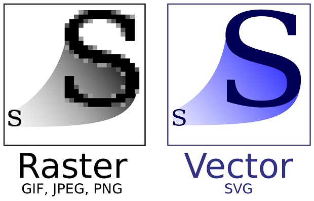
Rastered images is the technical term for regular photographs where data is stored as matrix of individual color coded dots called pixel(s).
Vectors are mathematical entities stored as simple functions for lines (vectors), connected or not.
Rastered images are limited by the visual size and color accuracy of the pixel matrix while vectored images are limited by the number of vectors. This means vectored images can scale in size indefinetly while scaling rastered images in size only changes the area covered by each pixel.
These days it’s possible to convert between both types but the change from rastered to vector isn’t perfect. Assume the change from vector to raster to be lossy, as in there is loss of information that likely can’t be recovered.
In digital fabrication vectors are easy for machines to follow so CAM software prefers it. Raster can still be used in some use cases like warming a specific area of acrylic for bending but it’s mostly used to apply photographic images or text to objects.
GIMP

GIMP, short for “GNU Image Manipulation Program”, is used to manipulate pixels. Most people have heard of Photoshop and Gimp is it’s open source brother from another mother.
If you want to give it a try you can download the latest version from here.
MS Paint
That said I mostly use Paint for quick and dirty cropping/resizing… GIMP takes too long to boot.
MS Paint has been around since the 80’s. Microsoft has even started upgrading Paint with new features recently. Only on Windows 11 though.
Paint’s interface is quite straight forward. Tools up top and not much else.
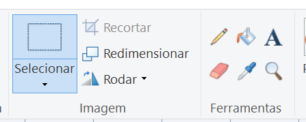
Like all others the select tool is probably the first one you’ll need to figure out. Just left-click and size the box as you will.
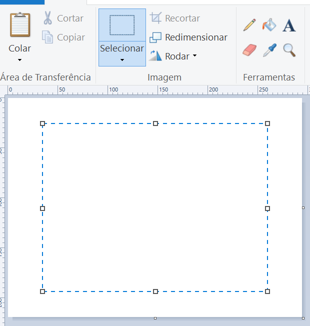
Do keep in mind you can’t resize the box after letting go as you’ll stretch the selected pixels. You have to start over the selection process. This might be the only annoying thing about using Paint for documentation.
The regular shortcuts Ctrl + X and Ctrl + V work so after selecting what you want to crop you can just cut it off.
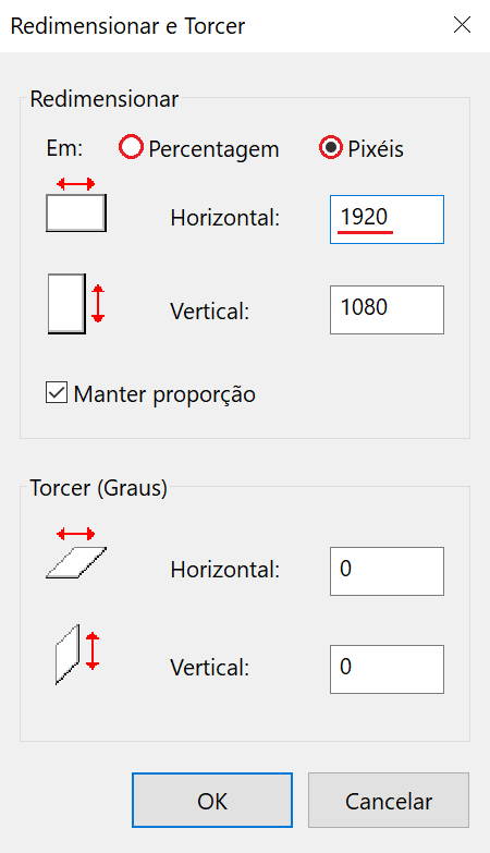
After cropping what I usually do is resize the rest of the image to 1% or 1px with the Ctrl + W shortcut.
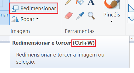
This will clear the old image and once you paste the pixels you cropped they’ll overlap the old image and clear everything and leave just the new pixels.
For documentation purposes picking a single width for media makes things look a bit more tidy. The 620px was purely random, should have made my life easier and picked 640…
If it’s a picture you took with a camera you can resize it or crop it some more.
When saving the image you should be aware that a simple crop of a screenshot will use less space as a .png than a .jpg. Probably has to do with uniform basic colors. Sometimes it’s easier to add an image with html and leave it as a .png than resize it to jpg. Same size and you get better legibility.
Strategic cropping helps with both file sizes and just understanding what’s in the picture which is kind of the point of documentation anyway. By the end I was using html for a lot more images, especially screen shots of text… Avoid resizing and .jpging those.
Inkscape
Inkscape is a vector manipulation software similar to Illustrator.
This link should take you to the latest release of Inkscape. In my case was version 1.1.2.
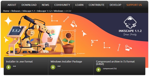
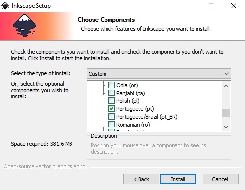
During the instalation if you want to save some space I’d recomend removing all translations and picking only the default English and maybe your 1st language in case you ever need it.
After installing and opening a new document I’d recomend checking out the Document settings and setting units to mm:
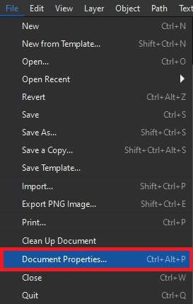
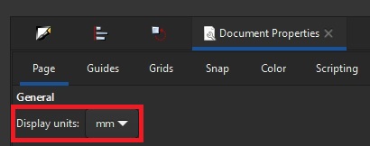
This way you can have a better sense of scale.
Slip Ring PCB
To start you’ll want to pick how big you want the slip ring to be, how wide the tracks, how far apart the tracks are and how big of an opening the ring should have.
In my case I was aiming for a pcb around 38mm wide with an 18mm opening, 3x 2mm tracks and 4mm gaps between them.
First basic task is to create 2x circles, 1x38mm in diameter and 1x18mm.
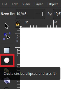
Quickly create a roundish shape:
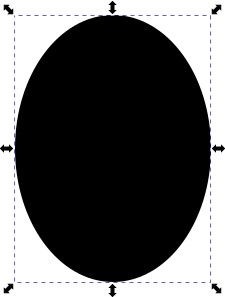
Up top you’ll have size and coordinates. You might have to change coordinates when snapping (an automated assistance in CAD programs to make sure objects are touching in specific ways) isn’t doing what you need but for now we just want the size.

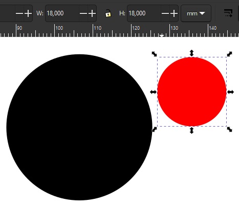
Now set the shape you had to 38x38mm and create a new one with 18x18mm. If you hold the Shift key on your keyboard while dragging the Circles tool it will fix the center point of the shape where you originally clicked. If you hold Ctrl then it will constraint the aspect ratio of the shape into a circle or a perfect square with the rectangle tool.
Next we’ll need to align the 2 circles. If the align tools are hidden the keyboard shortcut is Shift + F7. Press the vertical and horizontal align. (Later you should play around with the Relative To: option but it’s irrelevant for now.)
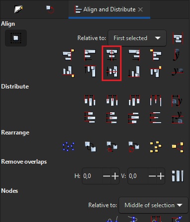
Select both objects by holding Shift + clicking them and align them.
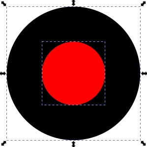
With both on top of each other select them both so we can use the small one to cut a hole in the big one. Look for the Path drop-down menu and select Difference.
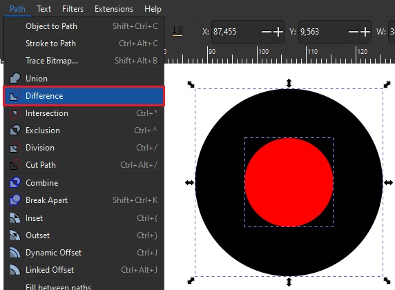
And that’s the outline of the PCB.
Repeat that as many times as needed for as many tracks as needed but taking into account the difference between the big circle and the small circle will be the width of the tracks/traces. I did it 3 times.

Since the cables would need to connect from the other side as to not obstruct the rotating contacts we’ll need to add hole cutouts so cables could be soldered to the tracks.
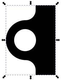
I made a nice shape to thicken the tracks for the holes but as long as it’s to the side of the tracks, guarantees contact of the wire and track once soldered and doesn’t obstruct the contact scructure once everything is assembled it’s fine. Be careful with the size of the whole, make sure it’s the size of the bit you’ll use to drill the board. If the drill is a lot wider than what you planned you might have problems.
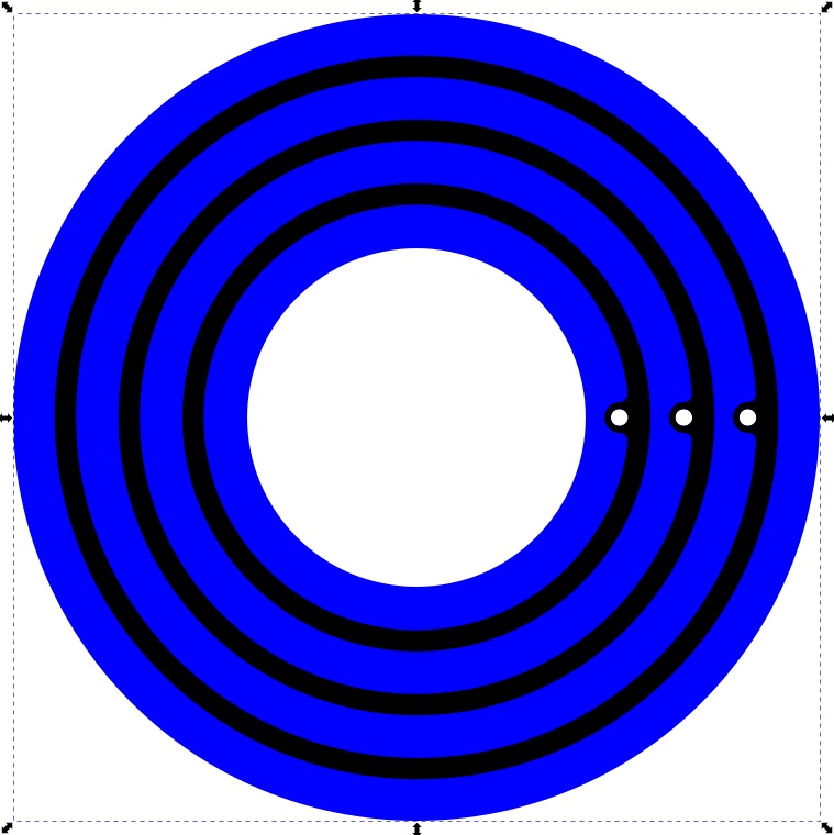
Alignining the small circles for the cables with the track holes can be hard, you might need to use the coordinates to help but you can also hide any small missalignments of circle cutouts in the board with the overlayed track circuits.
FreeCad
This link should take you to the latest release of FreeCad.
Downloading and installing the latest version of FreeCad is pretty straight forward. Just click next a few times, nothing noteworthy in there besides changing installation folder if you’re into that.
Rico Kanthatham suggested we give a Mod for FreeCad called Assembly3 which I installed but haven’t looked into yet.
You can clone the repository but for quick and easy installation find the .zip file of the master somewhere in here. With some luck this link will lead you straight to the file. (For updates you’ll have to go back and download them manually, instead of just using the pull command)
Unzip the contents into this folder on your Operating System of choice:
- Windows: c:\Users\<your_user_name>\AppData\Roaming\FreeCAD\Mod
- Linux: /home/<your_user_name>/.FreeCAD/Mod
- MacOSX: /home/<your_user_name/Library/Preferences/FreeCAD/Mod
For the next part, if you have a Windows computer like me you might need to install Python, which you can quickly get from here.
Now to quote the github installation tutorial:
For Windows, open a command prompt window, change directory to your FreeCAD installation directory, e.g. cd c:\Program Files\FreeCAD\bin. And install the solver by running command:
python.exe -m pip install py_slvs
IMPORTANT: For Linux and MacOSX, simply use your system Python to install the the solver, e.g. Python3 -m pip install py_slvs. The workspace will not function properly without a solver installed!
To make sure it’s installed check the workbench list for it.
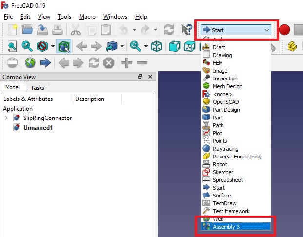
Remember where the workbench list is because it’s central to how FreeCad works.
Also you can pick multiple camera and navigation controls. They can be changed in the settings on the bottom right corner. I prefer Blender like controls and I also changed the View to Perspective. You should spend some time in the settings getting things to how you like, or might be used to from other places.
Slip ring connector PCB and metalic prong things
Between me starting to model and document all this I saw the parametric, algorithmic, generative design recitation and picked up on a lot on FreeCad from Babken Chugaszyan’s portion on parametric design inside FreeCad. If you want to see it here’s a link and it should be embedded below as well:
Open FreeCad and click the new project in the homescreen interface.
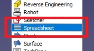
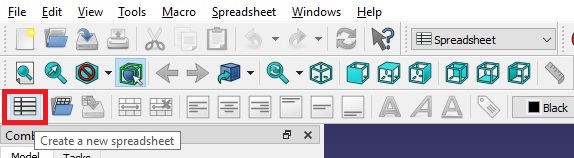
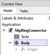
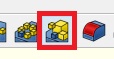
Once inside the new project the 1st thing is creating a spreadsheet with the Spreadsheet Workbench
With the spreadsheet created it’ll show up in the object list and if you have it open for viewing/editing it will show up in the navigation tabs at the bottom as well.
Fill up all the data you might need since we can link to it later.
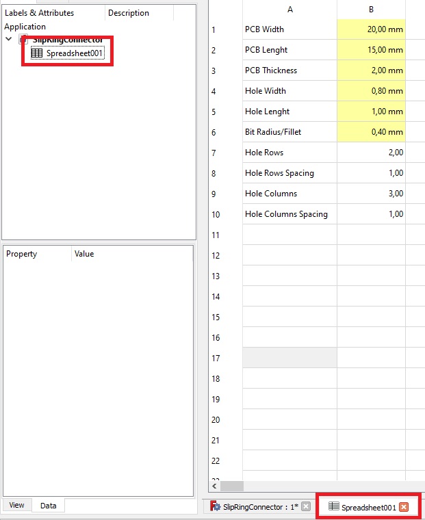
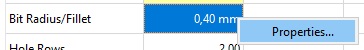
Yellow cells mean I have already given it an alias so it’s easier to remember which has what. Just right-click the cell, open the properties and head to the Alias tab.
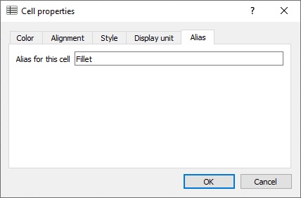
If you want to add display units there’s a tab for that too.
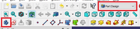
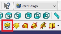
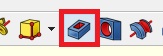
Now we need to create a body in the Part Design workbench.
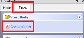
As that only created the abstract object press the Tasks tab and
Pick the plane you want to work on, I usually pick XY plane which means the viewport will have a better view of the object from the Top.
In the sketch workbench you’ll mostly focus on adding lines and constraints, which is how the lines relate to each other. The objective of to have a full constraint sketch so we know what all lines are up to. If the sketch has any degree of freedom it might get distored when moving around or have some unintended consequence further along.
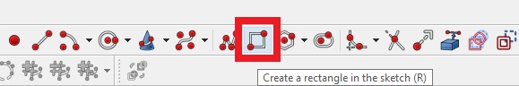
We need a rectangle, you can create 4 individual lines but there’s a rectangle tool. Doesn’t matter where, just crate it.
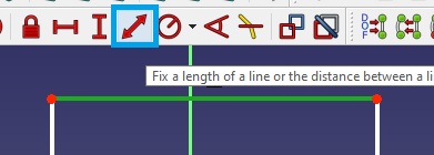
Once it’s created we’ll add size constraints by linking back to the spreadsheet. Pick a line and click the Fix Lenght constraint.
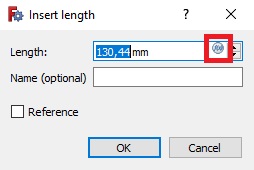
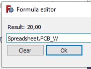
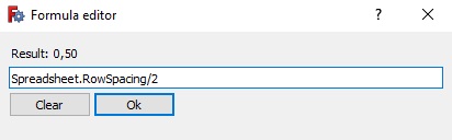
Click on the small button in the text box corner to open the Formula Editor.
Since there’s only 1 spreadsheet you can just start calling it but if you renamed any you had they’ll show up as <<NAME>>
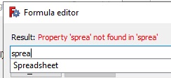
Inside the editor you can have basic math formulas and see the result can come in handy. But no need for formulas now, just link to the alias created in the spreadsheet.
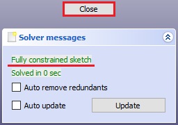
After constraining the PCB’s length and width one thing I like to do is add a symmetry constraint at the origin to make sure the sketch doesn’t go anywhere. Select 2 oposing points + the origin and click the symmetry button.
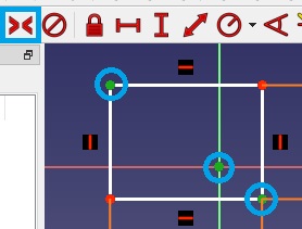
And we have a fully constrained sketch now. #Yey
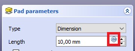
Close the Sketch Workbench and back on the Part Design Workbench and click on the Pad function so we can add thickness to our 2 dimensional sketch.
Click the forumla editor again and select the alias for the thickness of the PCB.
And boom we have a fully constrained solid with the variables linked from the spreadsheet.
Now we can use a face of the finished object to start a new sketch, which we’ll do; for the holes.
The first time I did this I tried cloning inside of the object but it was a bit too hard and the constraints weren’t linked as I expected. I’m guessing it might be to limitations on how FreeCad handles assemblies of objects and action hierarchy. If you’re reading this it means it worked so lets get to it.
After creating a standard box and constraining the length and width for the basic shape of the whole we’ll need add 2 intersecting dots to the narrowest sides to account for the drill bit.
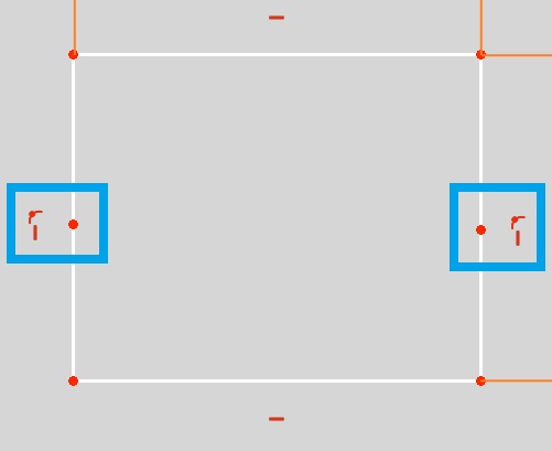
The points need to be in the middle of the lines and the symmetry tool can achieve that. Select the soon to be mid-point last and click the button.
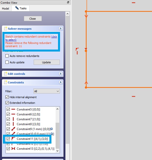
OH NO! Red messages! Something’s broken…

It’s fine. You can fix it, read the message: Redundant constraint. Just go to the list and delete the one we don’t need any more.
Do it again for the other side. To avoid this specific problem on mid-line points don’t add the point to the line as the symmetry tool will figure it out automatically. Just put it somewhere close to select it easily once you need it.
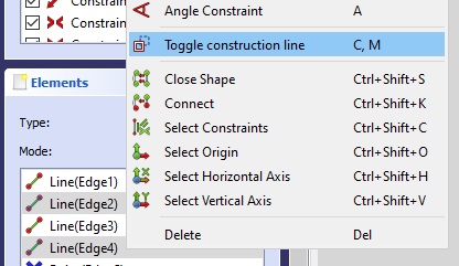
Another trick up our CAD sleeve we now is to select both lines that have the mid-points and turn them into Construction Lines. These are lines we can use while designing our objects but that will be ignored once anything is exported from the program. With the lines you want to convert selected right-click and toggle them as Construction Lines.
Next step is creating the Arch that accounts for the drill-bit diameter. In this case we’re assuming the width of the hole is as wide as the drill-bit but we could have a fancy formula to calculate 2 fillets and another edge where each fillet would be constrained with half the bit diameter we have in the spreadsheet and the edge between them would be what ever was left from hole_width - (2x Drill_Bit_Radius).
But since we don’t need any of that just pick the circle tool, select the center point and guide the tool to the edge. Do it for both sides.
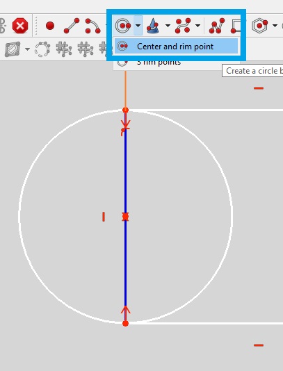
As we only need half of the circles we created let’s trim the excess off. Select the tool and just click the excess lines to trim. In this case the inner parts of the circles.

Only 2 degrees of freedom left to constraint. First we’ll do the spacing between rows which is the spacing between holes for each individual track contact. Define the distance of the hole to the center line of the board as half the distance in the spreadsheet.
The last constraint is pretty irrelevant, do what ever as long as you leave space for all the tracks you need. It might say the last constraint is redundant, but it’s not the problem. Once you delete it it should complain about another partially redundant constraint. Ctrl + Z the last constraint back into existance and delete the partial constraint it was complaining. Should fix everything.
Create a Pocket, which is just the opposite tool of the Pad.
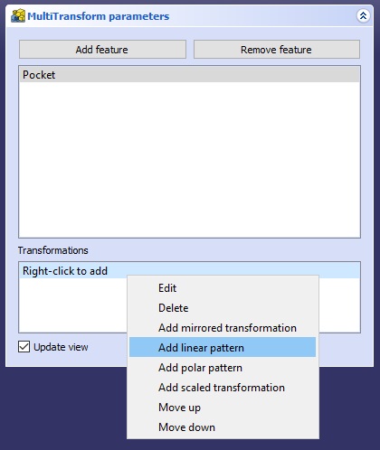
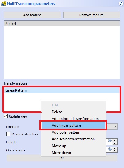
I needed a pattern of 2 rows of 3 columns and after much trial and error with cloning sketches and linear arrays, mirros and other attempts at multiplying the pocket DuckDuckGo told me the MultiTransform tool was my only option but I didn’t work like I expected at first.
First time I tried this I wanted to add both columns rows but each step has to be complete individually. Add the first linear pattern by right clicking the Transformations box.
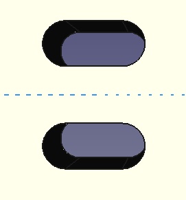
Some default settings need to be changed to get the correct orientation.
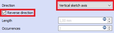
Everything was correctly input but placement is still off.
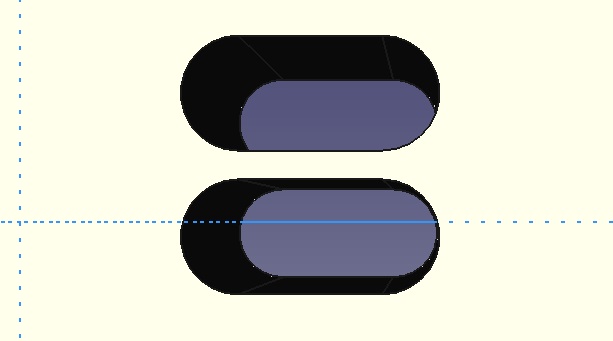
It appears the linear patter is measuring the distance from the opposite side so it’s just a matter of editing the distance link to add the hole width.
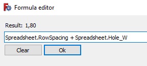
And fixed!
Double click the MultiTransform feature in the body tree and add another Linear Pattern.
Change settings as needed and for the Length formula I had to force my tired brain late at night to come up with something that should take into account the spacing between holes. Which might be an issue with the tracks on the other PCB I made in Inkscape.
(Spreadsheet.Hole_L + Spreadsheet.Hole_W + Spreadsheet.ColumnSpacing) * Spreadsheet.Rows - Spreadsheet.ColumnSpacing
Now I wanted to shape the connectors that would touch the tracks but it’s late and i need to get some sleep.
05/02/2023 Update
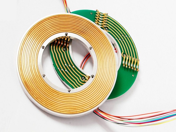
Got back at it, modeled some quick contacts that’d go on the small pcb component of the slip ring. In the end I didn’t need to make a slip-ring but it might have looked something like this:
Git Bonus
Had some files in the Staging I didn’t want to commit yet so went to look and to remove everything from the staging I just needed to run the command:
git reset HEAD -- .