13. Output devices
Editor’s note 2023
This was previously assignment 11.
Group Assignment - Power Consumption
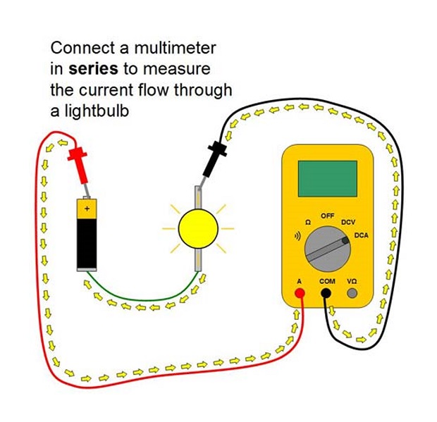
Unlike voltage that is measured in parallel; current must be measured in series. The multimeter has to become part of the power loop of the device. As the voltage is usually set, once we know the current we’ll know the power consumption.
At first I wasn’t getting a reading because I forgot to change the probe to the Current Measuring position. Always check if your multimeter probe is in the currect place, just moving the dial might not be enough.
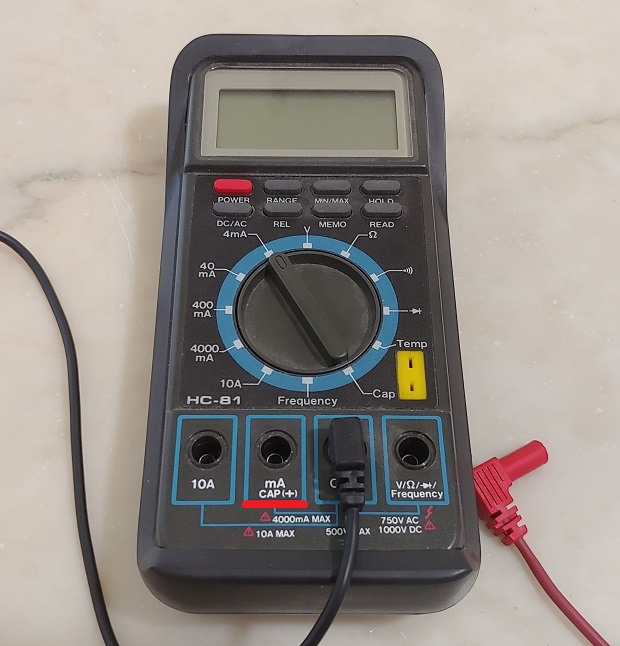
For this assignment I wasn’t sure what output component I could measure. The only display I had was already soldered to the board. To finish quickly most people seem to go for simpler components like motors and through-hole LEDs. I remembered I had some Piezzo Buzzers for my final Project. Store has them as being made by Cre-sound Electronics but no specific model. Specs say 3-20V and max 15mA.
Here’s me using an Arduno Uno as a 3.3V power supply:
For documentation purposes I should have used a higher order of magniture. Showing that last decimal point is quite pointless. If I had to take a guess fancy multimeters will probably warn us if we have hidden digit.
Let’s run the math: Voltage was 3.3V, we measured ~2.18mA and W = V x A so that gives us 3.3 x 0.00218 = ~0.00719mW.
I also tested at 5V:
Interestingly it pulled more current, even with a higher Voltage. Measured ~3.24mA so that gives us 5 x 0.00324 = ~0,0162mW. Over twice as much. It did indeed sound louder at 5v. To hit the 15mA max rated current it probably needs 20V.
If you want to read more about using a Multimeter here’s a nice tutorial.
Individual Assignment - TFT Display
For this assignment I wanted to use a display. My best option was salvaging a tft from some old RAMPS LCD Controllers. They belonged to very old nonfunctioning 3D printers that no one had yet fixed.
Kinda forgot to take a picture but they look like this:
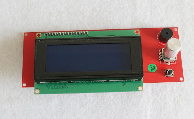
Took a while but finally figured out the exact maker and model I had: Powertip PC1602LRS-FWA-B-Q.
And found a datasheet which was nice:
Pin assignment seems like a standard across all LCDs.
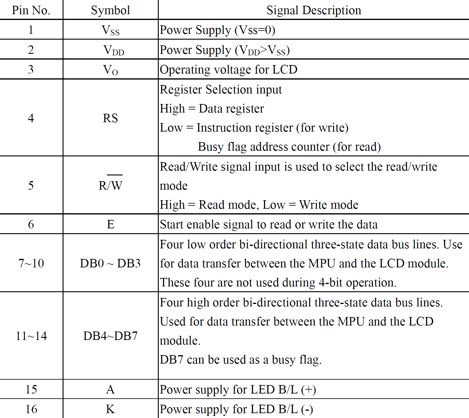
But this one’s special on the placement pins 15 and 16.
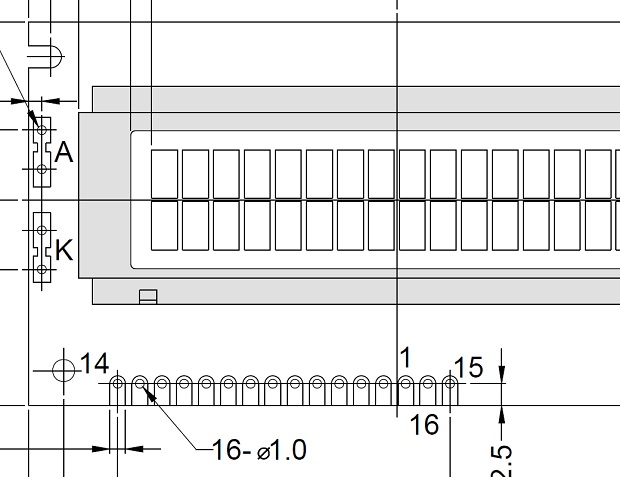
Eventually I figured out which pins required a connection to where.
This is the rats nest I had before milling the final board…
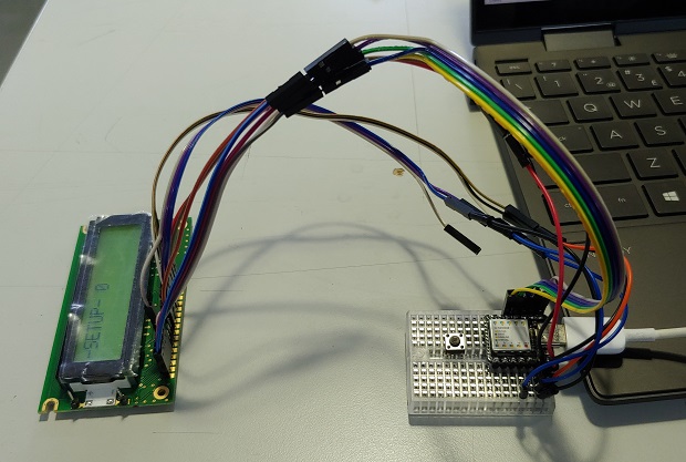
In a 4-bit operation LCD pins DB4-DB7, RS and E connect to GPIOs, R/W to GND, Contrast Adjust to GND too.
Editor’s note 2023
Contrast can be connected to a potentiometer and most examples had a resistance but for testing it I’m sure it’s fine.
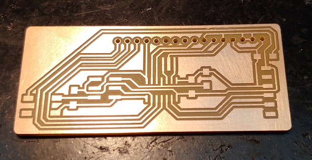
This was also before I learned to edit footprints, the pads for the through-holes were too skinny and were mostly non-existant after drilling. Nothing an excess of solder couldn’t fix.
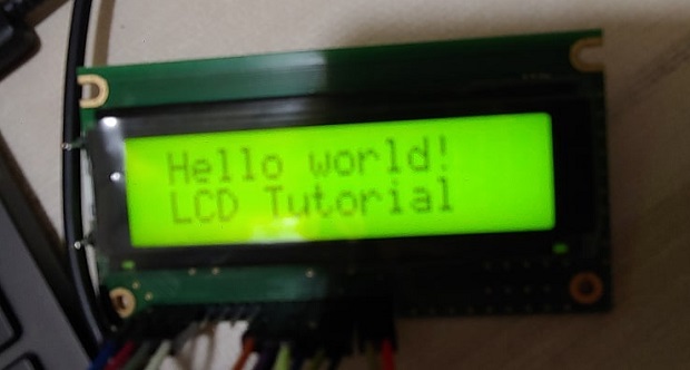
Look at it workin’!
This is the code.
#include <LiquidCrystal.h> // include the library code.

LiquidCrystal lcd(8, 7, 6, 4, 3, 2); // Creates an LCD object. Parameters: (rs, enable, d4, d5, d6, d7)

int counter = 0; // Just a variable for some counting later.

// The library allows us to create a handfull of custom characters that we can use as custom icons. They're represented by a 5*7 bit array that directly translates to pixels being either on or off.

//Smile emoji
byte smiley[8] = {
  B00000,
  B10001,
  B00000,
  B00000,
  B10001,
  B01110,
  B00000,
};

// A set of 4 custom icons to help generate a low battery animation
byte BatEmpty[8] = {
  B01110,
  B11011,
  B10001,
  B10001,
  B10001,
  B10001,
  B10001,
  B11111,
};

byte BatEmpty_Blink[8] = {
  B01110,
  B11011,
  B10001,
  B10001,
  B10001,
  B10001,
  B11111,
  B11111,
};

byte BatHalf[8] = {
  B01110,
  B11011,
  B10001,
  B10001,
  B11111,
  B11111,
  B11111,
  B11111,
};

byte BatFull[8] = {
  B01110,
  B11111,
  B11111,
  B11111,
  B11111,
  B11111,
  B11111,
  B11111,
};

void setup()
{
  // Initiates the custom characters
  lcd.createChar(0, smiley);
  lcd.createChar(1, BatFull);
  lcd.createChar(2, BatHalf);
  lcd.createChar(3, BatEmpty_Blink);
  lcd.createChar(4, BatEmpty);

  // set up the LCD's number of columns and rows:
  lcd.begin(16, 2);

  // Clears the LCD screen
  lcd.clear();
  // More of a debug instruction set to make sure it moved from Setup() to Loop() while I was figuring out the pins. Can be changed or removed.
  lcd.print(String("-SETUP- ")+String(counter));
  delay (5000);
  lcd.clear();
}

void loop()
{
  delay (1000);
  // Print a message to the LCD.
  lcd.home();
  lcd.print(" Hello world!");

  // set the cursor to column 0, line 1
  // (note: line 1 is the second row, since counting begins with 0):
  lcd.setCursor(0, 1); // Each character is set individually so the coordinates for each change must be included
  // Print a message to the LCD.
  lcd.print(counter); //Shows original counter or the counter set last loop.
  counter++;
  lcd.setCursor(3, 1);
  lcd.print(counter); // Show the state of the counter after it added +1
  lcd.setCursor(15, 1);
  lcd.write(byte(0)); // Puts the smiley on the lcd
  lcd.setCursor(15, 0);
  lcd.write(byte(1)); // Starts running the empty battery animation
  delay (1000);
  lcd.setCursor(15, 0);
  lcd.write(byte(2));
  delay (1000);
  lcd.setCursor(15, 0);
  lcd.write(byte(3));
  delay (1000);
  lcd.setCursor(15, 0);
  lcd.write(byte(4));
  delay (1000);
  lcd.setCursor(15, 0);
  lcd.write(byte(3));
  delay (500);
  lcd.setCursor(15, 0);
  lcd.write(byte(4));
  delay (500);
  lcd.setCursor(15, 0);
  lcd.write(byte(3));
  delay (500);
  lcd.setCursor(15, 0);
  lcd.write(byte(4));
  delay (500);
  lcd.setCursor(15, 0);
  lcd.write(byte(3));
  delay (1500);
  lcd.setCursor(15, 0);
  lcd.print(" ");
  lcd.setCursor(15, 0);
  lcd.write(byte(4)); // Battery is empty.
  delay (500);
}
Is the button useless? Not really, it came really in handy to jump over those 3 traces :P