8. Computer Controlled Machining
Group Assignment
Safety
Lasers are dangerous but chances are a fire is the worst outcome of being careless. Larger CNCs are a couple orders of magnitude above in terms of danger. Those motors/spindles don’t care about how soft and squishy you are so respect them. Even the end-mills and bits can be sharp enough to cut you powered down if you move your hand or arm a bit too close.
At best they’ll just hurt you and at worst they can kill you.
Routers are turning thousands of times per minute so careful with long hair and/or sleeves too.
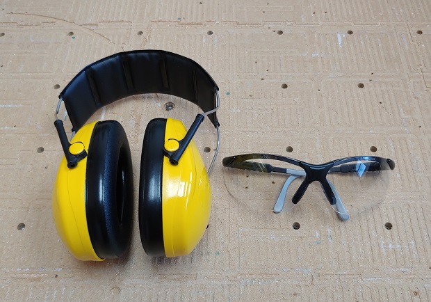
Common sense and safety glasses are the bare minimum you need to operate a CNC. Most of the times hearing protection is a good bet since things can get loud too.
Fixturing
Making sure the materials stay put is the 2nd part of the safety ritual. Lock that thing down. CNC’s usually include some clamps but there are plenty of options.
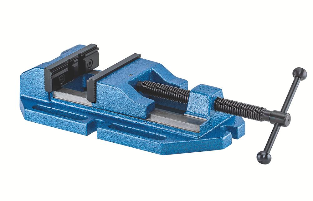
A nice vice like this one made by Roehm has the advantage of helping to hold on to round stock:
Maybe some get some fancy Tiger Clamps. Anything goes as long as your stock doesn’t come off flying. Always bad to ruin your stock since you might not have more of a certain (maybe expensive) material and no one likes getting hit in the eye with a flying block of wood or metal.
Machine Setup
To make sure you know what you’re getting at the end of each cutting job it’s important to make sure the machine has been well maintained (part of this kind of safety related too). Quick check for loose cables and such. All the mechanical parts are clean and lubricated enough. One thing people never check until it’s too late is the flexible link between motors and lead/ball-screws. Metal ones eventually fatigue and the rubbery ones degrade with times as well. This can be quite catastrophic if it’s a machine with twin motors/screws on a single axis and only one fails.
There are 2 extra important steps that you should be aware: tramming and step calibration.
Tramming
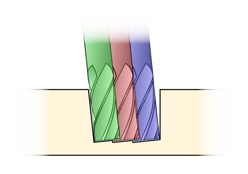
Tramming is just the act of making sure the router cutting axis is perfectly perpendicular to the cutting plane atop the machine surface.
There are plenty of resources online and even a quick search of Fab Academy documentation shows Walter Lenigan’s notes going a bit into tramming and links to an ok article on the subject. Does have a nice diagram:
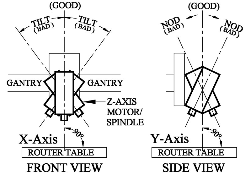
They kind of go a bit over board with the comparators. You can do it with just a half-stiff half-maliable piece of metal wire that you bend into an S and stick in a collet. Now turn it a few times and adjust each axis accordingly. If it’s scratching on one side, push it towards the other side. Keep lowering the Z gantry until you run out of screws to tighten. The wire should be longish but it must be able to complete whole circumferences.
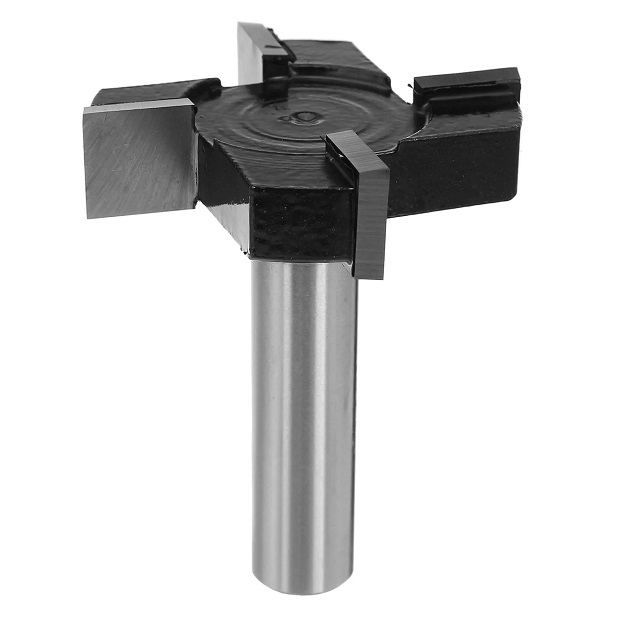
If it’s a new spoilboard you should run a Surfacing toolpath with an appropriate end-mill for your material.
They can look like this:
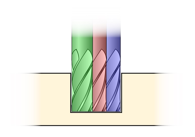
After the 1st surfacing pass there should be a wavy pattern on the material that’s cause by the misaligned cutting axis:
Once you’ve finished tramming surface it again. The lines will probably still be visible depending on the material but you shouldn’t be able to feel them with your fingers.
Here’s the website I got those great pictures in case you want to read some more.
Step Calibration
Stepper motors have well defined steps/rotation but leadscrews and such are always different so it’s vital to configure the correct values for steps/mm within the machine so that if you ask for a 1cm*1cm*1cm you end up with one instead of 1.03*1.1*0.98 cubish solid.
Plenty of resources online so no point in going into much detail but in 2022 the Kannai lab documented the process of calibrating a ProverXL 4030. The important values to change are $100, $101 and $102. Cut some squares (for X and Y) and drill a few holes (Z). Measure them, run the math and adjust accordingly.
Materials
Materials… Some are soft, some are not. Being soft in of itself doesn’t guarantee good machinability. For example Aluminium, a metal on the softer side as well as common plastics can be very hard to machine for different reasons with similar symptoms. If you cut both wrong they’ll melt around your tooling until it stops cutting, glues itself to the stock leading to a tug of war between the tool and the CNC’s motors to who will succumb first.
Chip Load
As a very minimalist explanaition, chip load of the size of a chip. It’s how much each flute cuts, how much strain is put into the tool for each cut. Materials like to be cut in a certain way and chip load is a good starting point to figure things out. The tools you use will sometimes tell you the maximum chip-load it can take. Although a lot of times they’ll just skip over that and straight up tell you the safe feed rate you can use.
Feeds & Speeds
Feed rate is the speed you move your cutting tool. It’s how much material you’re shoving/feeding your tools… Recomended values for common materials are easy to find online. There are tables, calculators and like I mentioned before even the tooling manufacturer will tell you how much you can push it safely and economically. Going too fast will wear out your bit more, possibly cause a bad finish or skipping steps. It can also break the tooling, maybe even free the stock if it wasn’t held down expecting so much force. There are free calculators everywhere, even CBA has one, but also paid services like provencut or cnccookbook that guarantee their values as trusthworthy.
Cut depth is a setting that is very dependent on the actual machine. How rigid it is and how powerful the spindle is; how much material the machine can keep clearing before slowing down/skipping steps (closed-loop motors on the axis help us stay at the threshold). The deeper you can go the better for tool life but the more strain you put on your machine. It will even sound awful because of all the resonances involved.
Toolpaths and Bits
Ok, full disclosure: I’m too sleepy so I tried to get ChatGPT to write these next paragraphs. The final prompt I was happy with the answer was:
Write me a couple of paragraphs about toolpaths types and cutting tools in cnc machining. By toolpaths I mean things like adaptive clearing and in regards to cutting tools just the general important specs like flute number and specificities worth noting like the existence of so called 0 flutes being 1 flute designed for the best possible chip ejection for aluminium or plastic milling.

I have already roughly covered materials, chip load and feeds & speeds elsewhere.

Focus solely on the toolpaths and cutting tools. No need for generalized intros.
And the reply was:
In CNC machining, the choice of toolpaths and cutting tools plays a pivotal role in determining the efficiency and precision of the machining process. Various toolpaths are employed to optimize material removal and enhance surface finish. One widely used strategy is adaptive clearing, a dynamic toolpath that adjusts the engagement of the cutting tool based on the geometry of the part. This method ensures constant tool engagement, minimizing tool wear and maximizing efficiency. It is particularly effective in clearing out excess material from intricate geometries.
Another essential toolpath is contour milling, which follows the outline of the part to achieve precise dimensional accuracy. This is crucial for creating complex shapes and maintaining tight tolerances. Additionally, pocket milling involves removing material from enclosed regions, providing a strategic approach for efficient material removal.
Turning attention to cutting tools, the selection of an appropriate tool is critical. The flute number, or the number of cutting edges on a tool, significantly influences its performance. Tools with higher flute numbers are generally used for softer materials, while lower flute numbers are preferred for tougher materials. In some specialized applications, tools with zero flutes, essentially a single-flute design, are employed for optimal chip evacuation, particularly in aluminum or plastic milling. The absence of additional flutes allows for better chip clearance, reducing the risk of chip recutting and improving overall machining efficiency. Understanding these toolpaths and cutting tool specifics enables CNC machinists to tailor their approach for diverse materials and machining requirements.
Pretty good I’d say.
When I was looking for mentions of chip load I found this page that does a small deep dive on tool paths.
It also links to this nice comparison video:
Shopbot also has a .pdf, most recent I could find is from 2016, which goes into another important spec of end-mills related to the type of flute design of which there are 4. Straight, down-cut, up-cut and compression. Straight are very robust and good at clearing material. Down-cut leaves a nice surface finish at the top while up-cut leaves a nice finish below. Compressions try to leave an ok finish on both sides but have really bad chip ejection.
Runout
Runout is one of those things that can be both irrelevant and very agravating. It might not matter for some jobs or materials but in others it can ruin a part or break every end-mill.
It’s essentially the unwanted property of the cutting surface being misaligned to the rotation axis. Leading both to wider cuts than expected and uneven forces being applied on the material and end-mill.
While I want to buy a comparator for myself I found that Dan Meyer has a good explanation on how to measure runout.
The most common culprits are the tool holding collet and the tool itself. In theory you can balance a bad collet with a bad end-mill but the point is to not have either.
Individual Assignment
For this assignment we had to make something big. Or bigish. Human scale… Chairs or stools seem like a popular option.
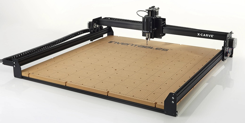
The large format CNC we have is an X-Carve by Inventables.
I remember my instructor telling me at the time that he had just finished upgrading it but now I don’t know if it was just the Z-axis Kit or the whole Upgrade Kit with new motors and stiffeners.
| Spec | X-Carve |
|---|---|
| Working Area (W x D) | 750 * 750 mm |
| Maximum Z Clearance | 114 mm |
| Accuracy | 0.127 mm |
| Router | DeWalt D26204K A.K.A. D611 |
| Router RPM | 16.000 - 27.000 |
| Router Power | 1,25 HP / 932 W |
| Collet | Dewalt Specific? (ER16-ER20?) |
| Total Indicated Runout | 0.01mm |
| Interface | USB |
| Size (W x D) | 1000 x 1000 mm |
| Weight | ~45 kg |
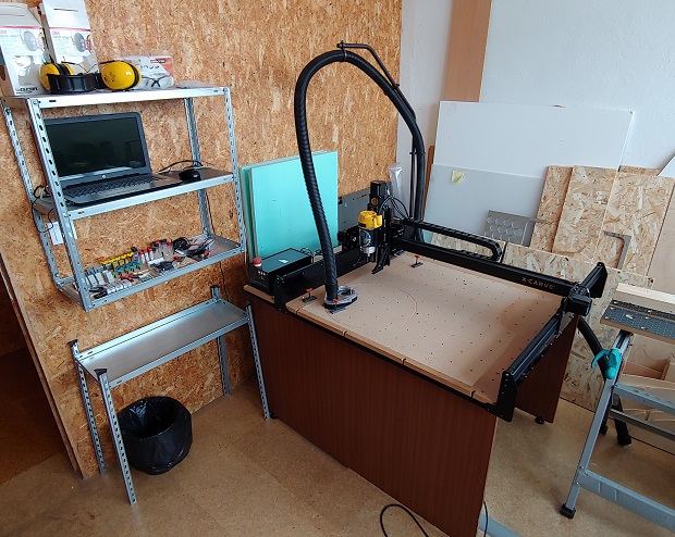
The X-Carve has it’s own room/storage since it’s so loud when doing it’s thing. The table could probably do a better job of dampening some of it…
Machining
This is the old way of doing things… Machining is the quintessential subtractive manufacturing process. Start with a big piece of stock and get it down to the shape you want. The opposite of additive manufacturing like 3D Printing.
In this case we’ll be Milling our part.
There’s also Turning on Lathes or Boring with Reamers or Single-point Cutting Tool, possibly also still in a lathe.
Designing
As I’ve always been fascinated by the inherant logistical efficiency of Flat-pack Furniture I started looking into what I could fit into a single 75cm*75cm piece of wood.

Eventually I found this table by Caesarstone. I think it’s just a showpiece for their Sintered Stone but the table does look really nice and I could do all of it in a single operation.
Modeled a simplified version that could fit into a single operation:
This is what it looks like assembled.
Now we need an .svg file to import into the CAM software. Open the Draft Workbench in FreeCAD.
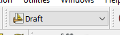
Select all.

Make sure everything’s actually selected…
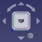
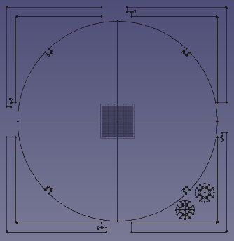
Set the viewport parallel to the plan you have your parts in as the drawf plan will be set according to where we’re looking at.
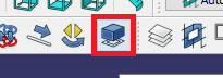
Click the Shape 2D View button.
Should look like this:
Select everything again.
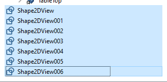
And make sure everything’s selected, again.
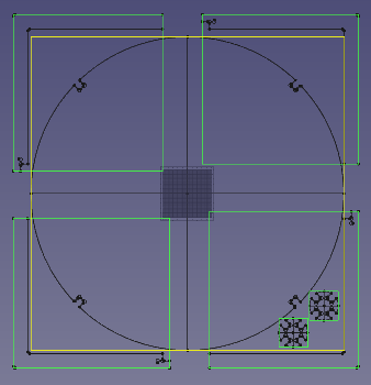
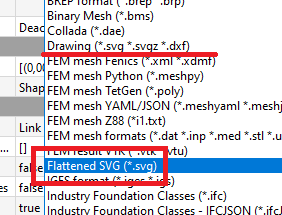
Export as a Flattened SVG. NOT as a Drawing.
Now we need to get it ready for cutting so open the .svg in Inkscape.
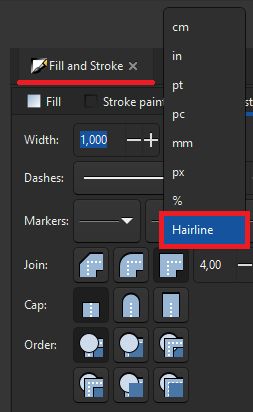
First thing is edit the line thickness to at least hairline so we can see any invisible 0 thickness line.
Select them all and go for it.
Remove those extra construction lines and save it.
Editors note 20-02-2023
There’s actually a way of cleaning the solids inside FreeCAD called Refine Shape. I only learned about it last week during this years Recitation on 3D modeling. Never noticed… :|
CAM - Easel
Inventables also has a nice freemium CAM software that works well with GRBL machines. It’s called Easel.
After the initial 30 day trial we only lose access to some config options of having more than 1 machine saved and some functions for special cutting tools.
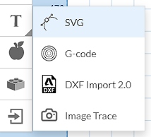
After registering go ahead and open a new project. Find the Import button.
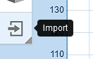
Import the latest version of the .svg file.
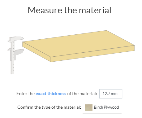
Make sure you configure the material and size correctly. Because of Russian’s invasion of Ukraine we couldn’t find any Plywood in Portugal for a while as a lot of it was imported from Russia. We had to settle for Oriented Strand Board (OSB). My instructor thought Birch Plywood would be close enough and I set it to that.
Confirm changes on the top right corner.

Moving .svg’s from one program to another usually leaves some clunky artifacts.
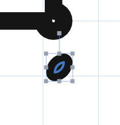
Gotta go back to Inkscape to fix it.
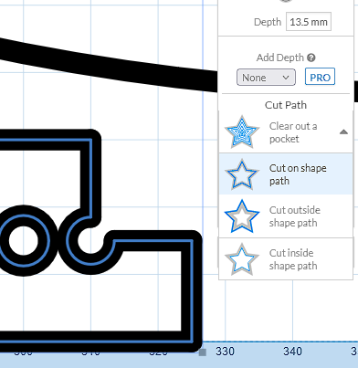
To get the correct dimensions cut we need to pick which side of the line the cnc will cut.
But Easel won’t let me… It won’t even show the menu to select which side we want.
Turns out the svg isn’t created as a single piece but as multiple individual lines.
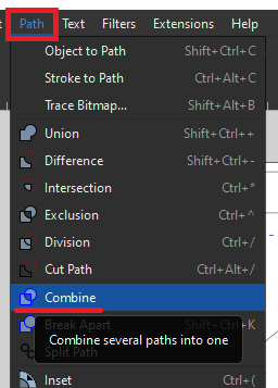
Back to Inkscape to combine them all.
Repeat it for every shape.
There we go. Now that it’s a single shape Easel can tell what side is in and what side is out.
CARVE!

Or maybe not…

Turns out joining all the lines into a single svg doesn’t automatically close the loops.
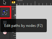
To select overlapping nodes we can’t move one as they’ll average each other’s coordinates.
We need to select the pair of lines we want to join with shift-click and use the Path -> Union function. As we need to do that to ALL lines to truly close the shape I suggest following them without stopping in a shape and using the keyboard shortcut CTRL++ if you want to have some sanity by the end.
Ater joining everything the Select interface will look different as it’s not showing all individual lines but just the final shape.
It took me a few tries but eventually I got Easel to accept all shapes as closed.
Editor’s Note
Full disclamer… Last year I actually found a plug-in for Inkscape that does this mostly automatically. It’s called Inkscape Chain Paths. It wasn’t perfect though; at least for my shapes I couldn’t just select everything and use it. It would break a lot of relationships between the lines, especially curves. I decided to look into how to do it manually in case the plug-in became broken in a newer version of Inkscape. And in case I ever found a shape that broke the actual plug-in and selecting less lines at a time wasn’t enough.
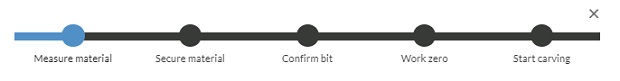
Easel shows a small preview of the setup algorithm.
Confirm thickness and material.
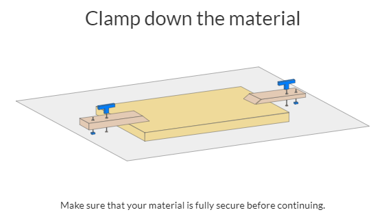
Secure material.
We’ll be using a 3.175mm 2x straight flute end-mill.
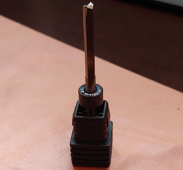
Check if the collet is secured correctly before inserting the end-mill.
Confirm bit (notice V-carving tools locked behind a PRO account).

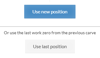
Now we need to set the Z-height origin. Let’s pick manual first.
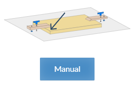
Move close to what will be the future X and Y origin of the object. Lower the probe in smaller and smaller steps as you get close to the surface of the material. People like to use a piece of paper, once the paper is stuck jog it up until it’s free and it’s good.
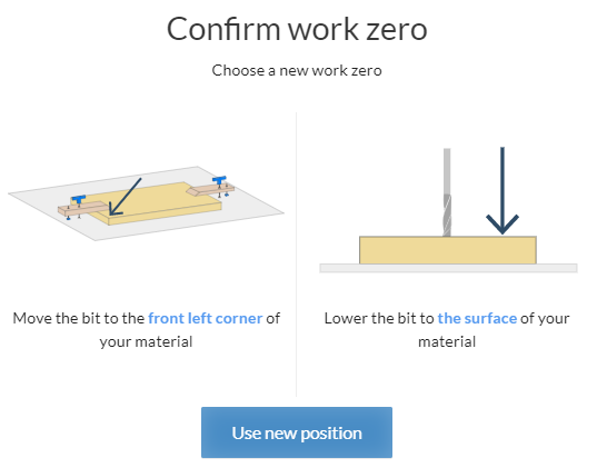
Use that new position.
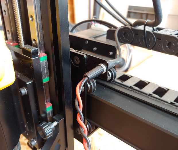
The quicker way is just to use the Z-prove. The one included with the X-Carve looks like this:
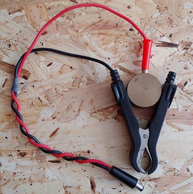
And plugs into the Z-Axis Assembly here:
Jog the machine to where you want to do the measurement.
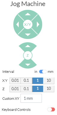
Put the probe under the bit and you can also lower the Z-axis closer to the probe as it’ll plunge at a very low speed for safety during the probing algorithm.
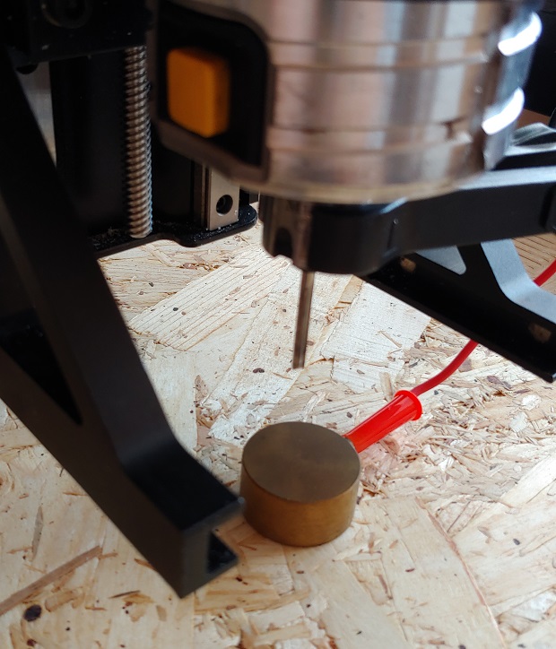
Follow the instructions.
When it asks to touch the bit just bop it with the probe.
Don’t forget to remove the Z-Probe unless you want to get smacked in the face with it....
Follow the last steps, including turning on the Dewalt Spindle.
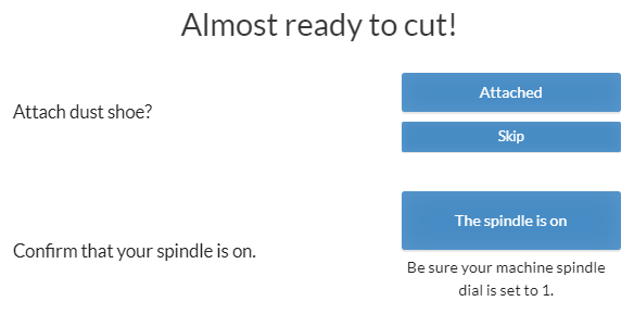
Remember this is a machine that can hurt/main and possibly kill someone so be careful. When starting it have your hand on the Emergency Stop button just in case something unexpected happens. (Learning to read G-code can help finding weird and unexpected actions.)

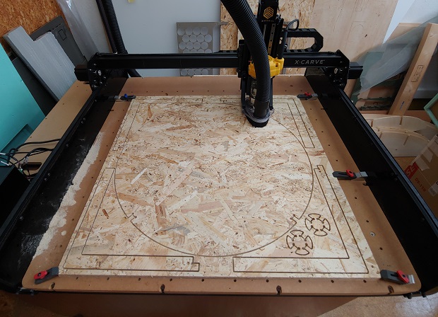
Let’s go Carvin’!

Editors note 21-02-2023
I should mention I did some kef testing to make sure everything fit together.
But OSB is very, very uneven in terms of thickness. Consider the thickness value it’s sold as more of a suggestion than a rule…
This means doing press fits with OSB will probably be nigh impossible.
Anyway back to the coffee table. First leg almost done.
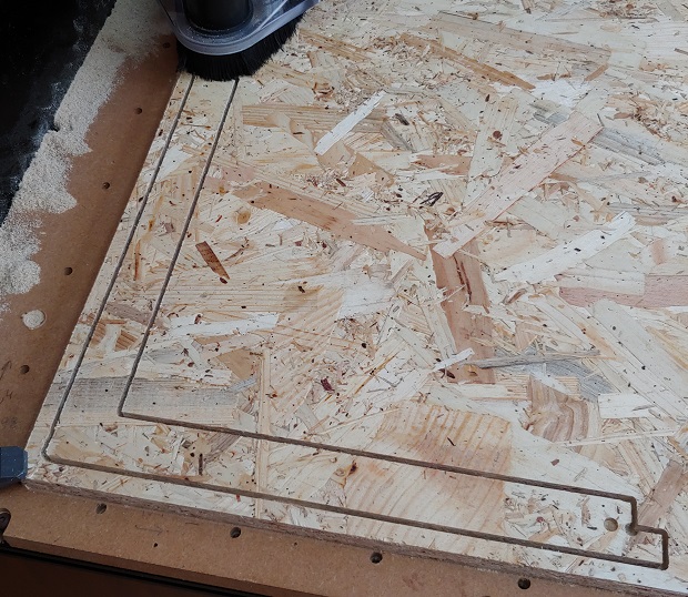
Last passes…
As expected some issues with material thickness. I could have dug a bit deeper, that is what the spoilboard is for but eh… It’s always hard to judge these things. A flat material is more important xD
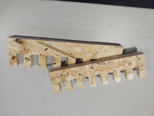
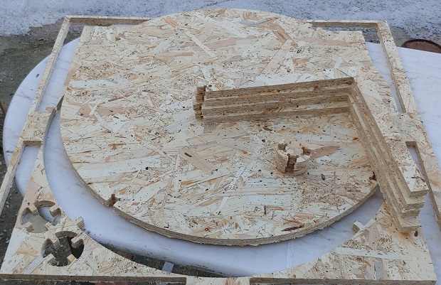
All parts.
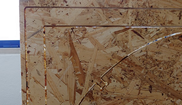
Had to clean some Rough edges.
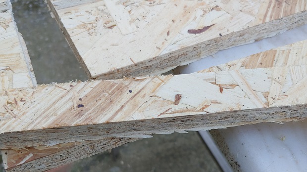
Nothing too bad.
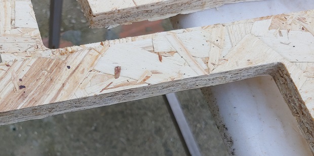
Not entirelly sure why one of the legs has a weird fit. Maybe shifting internal stresses of the OSB after milling?
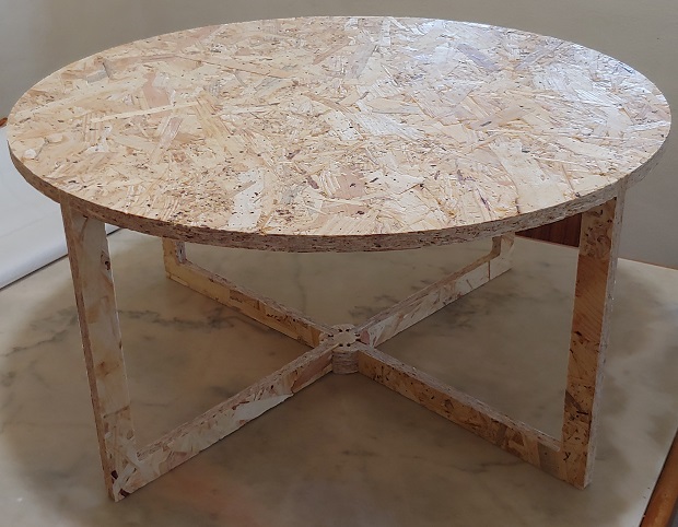
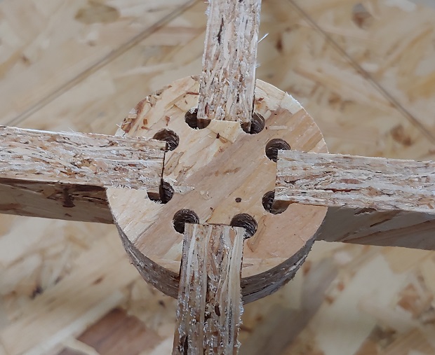
Fully assembled.
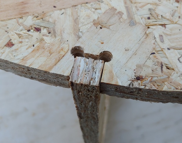
I knew I’d need a tension wire to make sure it didn’t fall appart.
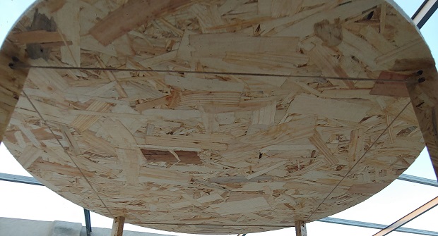
Managed to hide the knot in a leg opening. Speaking of which, I think I set the holes and corners too large with 3.175mm diameter instead of slightly above 3.175mm radious to make sure Easel could open them… Ah well.
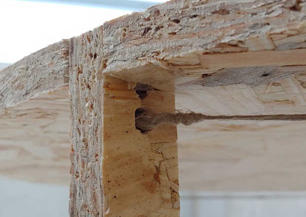
In hindsight I should have payed more attention to the bottom supports. They stabelize the legs well enough but they become a problem when moving the table as they’re mostly only held in place by the weird mechanical lever from the wire tension on the legs.
Files
Parametric Keft Test - FreeCad file
Minimum Waste Coffee Table - FreeCad file
Minimum Waste Coffee Table - Clean SVG