14. Networking And Communications
Group Assignment - Trade Messages Between 2 Devices.
Nueval is a bit ambiguous when it comes to this assignment. Some say I need at least 2 boards others say I can use a single board + computer… I’ll choose to believe the latter because while I have a few boards with LED’s I don’t have any with buttons that I could use here so it would make documentating this weird… :X
I picked my final project’s board since it has 5x LEDs and an ESP32 just in case I had time to try out webservers or websockets.
Since I did this “group” assignment after my Interface and Application Programming assignment I could edit that micro-controller code to interact with serial messages now and turn individual LEDs on and off based on received commands.
The relevant line of code is just: String input = Serial.readStringUntil('\n');. That’ll write the message received from serial up to the given character into the input variable. In that case it’s just the New Line character and those can be set in the program sending the messages, like Arduino IDE’s Serial Monitor or my serial monitor #SpoilerAlert.
Things were going well, I added variables to store the LED on/off state and the serial message:
bool red = false;
bool blue1 = false;
bool blue2 = false;
bool green1 = false;
bool green2 = false;
String input;
I setup the pins as output and initial off state:
void setup() {
  Serial.begin(9600);
  pinMode(D10, OUTPUT);
  pinMode(D9, OUTPUT);
  pinMode(D8, OUTPUT);
  pinMode(D7, OUTPUT);
  pinMode(D3, OUTPUT);
  digitalWrite(D10, LOW);
  digitalWrite(D9, LOW);
  digitalWrite(D8, LOW);
  digitalWrite(D7, LOW);
  digitalWrite(D3, LOW);
}
Reused the conditional check of an available serial connection before trying to read from it:
if (Serial.available() > 0) {
  delay(100);
  //Serial.println("DEBUG: waiting for input");
  input = Serial.readStringUntil('\n');
  //Serial.print("Received message: ");
  //Serial.println(input);

  **Spicy bits go here.**
}
And then things got interesting.
Initially I had a basic logic check to update the on/off state of each LED. Something like:
if (input == "red"){
  if(red){
    digitalWrite(pin, LOW);
    Serial.println(input + " off");
    red = false;
  } else {
    digitalWrite(pin, HIGH);
    Serial.println(input + " on");
    red = true;
  }
  input = "done"; // Clear input or it'll keep running the code.
}
if (input == "green1"){
  if(green1){
    digitalWrite(pin, LOW);
    Serial.println(input + " off");
    green1 = false;
  } else {
    digitalWrite(pin, HIGH);
    Serial.println(input + " on");
    green1 = true;
  }
  input = "done";
}
if (input == "blue1"){
  if(blue1){
    digitalWrite(pin, LOW);
    Serial.println(input + " off");
    blue1 = false;
  } else {
    digitalWrite(pin, HIGH);
    Serial.println(input + " on");
    blue1 = true;
  }
  input = "done";
}
if (input == "green2"){
  if(green2){
    digitalWrite(pin, LOW);
    Serial.println(input + " off");
    green2 = false;
  } else {
    digitalWrite(pin, HIGH);
    Serial.println(input + " on");
    green2 = true;
  }
  input = "done";
}
if (input == "blue2"){
  if(blue2){
    digitalWrite(pin, LOW);
    Serial.println(input + " off");
    blue2 = false;
  } else {
    digitalWrite(pin, HIGH);
    Serial.println(input + " on");
    blue2 = true;
  }
  input = "done";
}
But since it was all quite repetitive code I wondered if I could make it a bit more elegant with a dedicated function. Say:
void onOff(int pin, bool flag){ // LED pin, LED status variable
  if(flag){
    digitalWrite(pin, LOW);
    Serial.println(input + " off"); // Debug message
    flag = false;
  } else {
    digitalWrite(pin, HIGH);
    Serial.println(input + " on"); // Debug message
    flag = true;
  }
  input = "done"; // Clear input or it'll keep running the code.
}
That plus:
if (input == "red"){
    onOff(D3, red);
}
if (input == "green1"){
    onOff(D10, green1);
}
if (input == "blue1"){
    onOff(D9, blue1);
}
if (input == "green2"){
    onOff(D8, green2);
}
if (input == "blue2"){
    onOff(D7, blue2);
}
Worked partially. I could change the initial status of the pins, from off -> on or on -> off if I edited the starting state but not change it back. The error messages were stuck in a loop of the correct initial change so it had to be something with changing the value of the on/off flags.
Many hours later I found out the answer. Long story short it has to do with the way C processes parameter variables in functions, because of course it did. C uses what’s called Pass by Value meaning that parameters are copied into a separate entity while a function is running so in the end it’s not editing the original variable by default. Just using it’s contents. flag = false; or flag = false; weren’t updating the input parameter variable.
The ability to edit the contents of the original variable envolves Pass by Reference. Standard C doesn’t allow it but it can be emulated with the syntax mentioned in the article I linked. As I researched a bit further it turns out C++ has a simpler syntax for Pass by Reference. Just need to add a & prefix to my variable and that’s it…
So a few hours later I got this code to work:
bool red = false;
bool blue1 = false;
bool blue2 = false;
bool green1 = false;
bool green2 = false;
String input;

void onOff(int pin, bool &flag){
  if(flag){
    digitalWrite(pin, LOW);
    Serial.println(input + " off");
    flag = false;
  } else {
    digitalWrite(pin, HIGH);
    Serial.println(input + " on");
    flag = true;
  }
  input = "done"; // Clear input or it'll keep running the code.
}

void setup() {
  Serial.begin(9600);
  pinMode(D10, OUTPUT);
  pinMode(D9, OUTPUT);
  pinMode(D8, OUTPUT);
  pinMode(D7, OUTPUT);
  pinMode(D3, OUTPUT);
  digitalWrite(D10, LOW);
  digitalWrite(D9, LOW);
  digitalWrite(D8, LOW);
  digitalWrite(D7, LOW);
  digitalWrite(D3, LOW);
}

void loop() {
  if (Serial.available() > 0) {
    delay(100);
    //Serial.println("DEBUG: waiting for input");
    input = Serial.readStringUntil('\n');
    //Serial.print("Received message: ");
    //Serial.println(input);
    if (input == "red"){
        onOff(D3, red);
    }
    if (input == "green1"){
        onOff(D10, green1);
    }
    if (input == "blue1"){
        onOff(D9, blue1);
    }
    if (input == "green2"){
        onOff(D8, green2);
    }
    if (input == "blue2"){
        onOff(D7, blue2);
    }
  }
}
Here’s what it looks like running:
Also shout out to Kevin Kwok since he was the only other person to mention Pass by Value shenanigans.
Individual Assignment - 2x Boards Talking
There are a few different communication protocols that can be used by micro-controllers to send and receive messages from one another. These days it’s more common to use one of many Serial options.
Currently I2C and SPI might be the two most used protocols. CAN is being used more and more, especially in the automotive industry. There are also other variations like the audio-centric I2S and I3C which is an attempt to fix some I2C limitations.
Serial Peripheral Interface
The SPI wikipedia paragraph is quite succint:
The Serial Peripheral Interface (SPI) is a synchronous serial communication interface specification used for short-distance communication, primarily in embedded systems. The interface was developed by Motorola in the mid-1980s and has become a de facto standard. Typical applications include Secure Digital cards and liquid crystal displays.
The controller device can pick which device it’s talking to and the connection is Full-Duplex.
The base protocol needs at least 3x lines, SCK for the sync clock, MISO and MOSI are the input and output data connections. The Chip Select is optional if there’s only 1 connection.
I2C
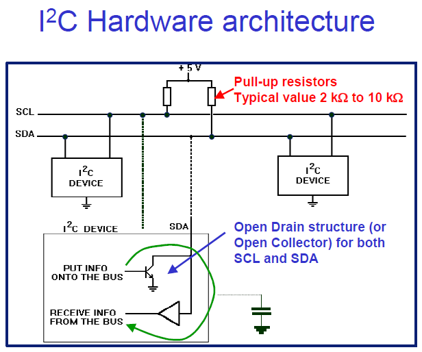
I already detailed how I2C works in my Input assignment but the short version is that the 2x I2C BUS wires are each dedicated to data (SDA) and clock (SCL). Data is sent and received in encoded bytes. The 1st of which is the address of either the receiving device or the targeted device identifing itself in the response.
Editor’s note 27-05-2023
Originally I designed the boards somewhat blindly to just mimic my other board with 2 LEDs that counts up in binary assuming it’d be easy to use the MISO and MOSI connections from the ISP link for a quick SPI connection. I tried using the SPI Library without success. As I started looking into more exotic options like 3 wire SPI it started to become obvious I should have done all this research before. I wasn’t sure I had enough free pins to do anything. Couldn’t try to use Serial, I didn’t connect both RX and TX to the FDTI link. Tried maybe forcing a Software Serial connection too couldn’t get it working either. In hindsight I should have done more search before making the boards and maybe use a micro-controller with more pins so I’d have some margin of error but oh well. Ended up forcing me to learn way more. As I was using I2C for my final project i just move onto that and maybe #YOLO something together. This started with maybe getting SPI to work and ended up with me bit-banging my own protocol.
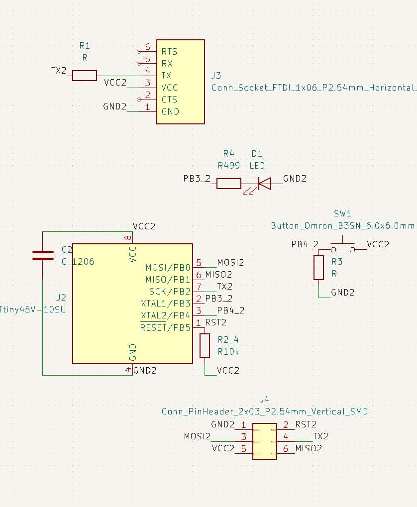
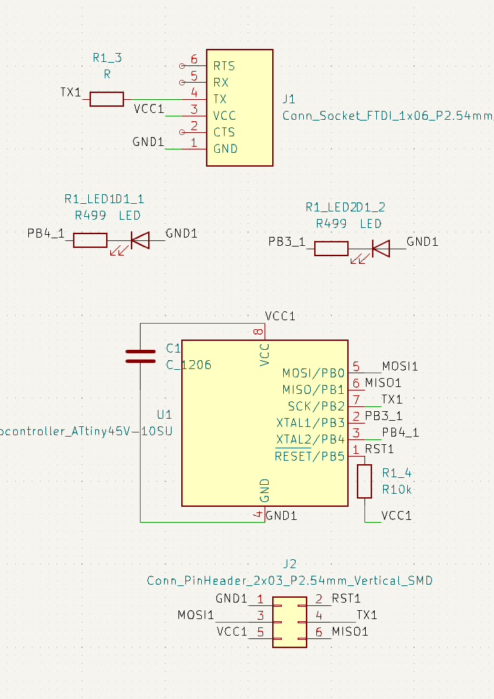
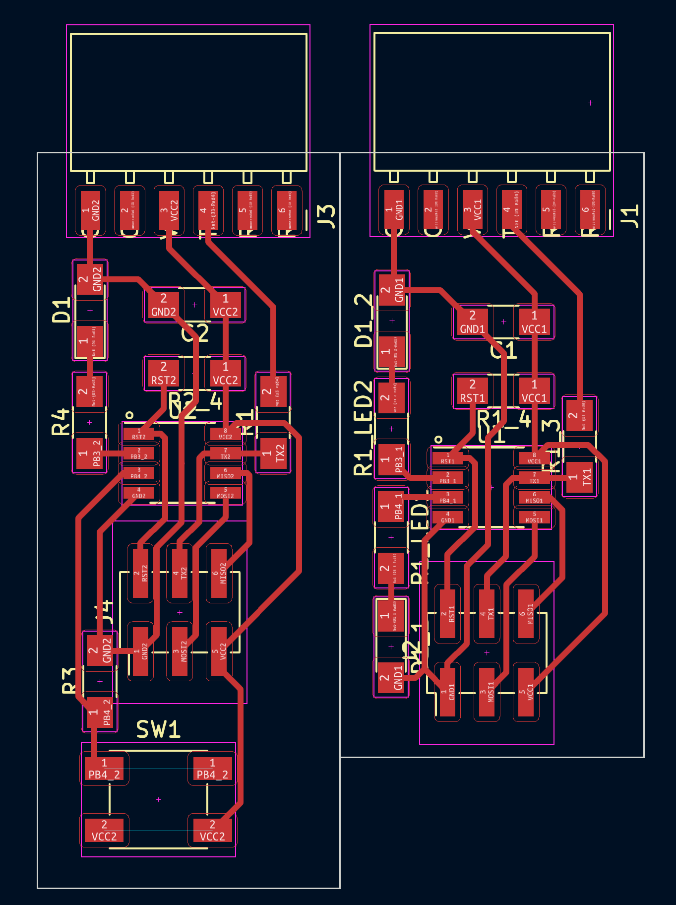
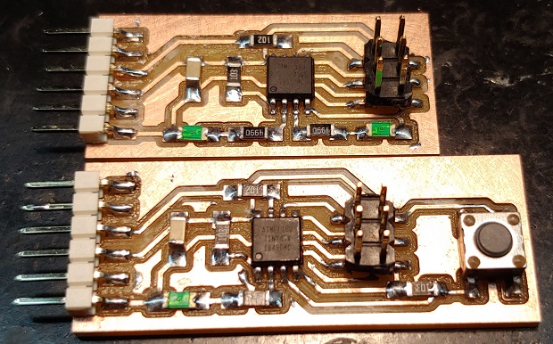
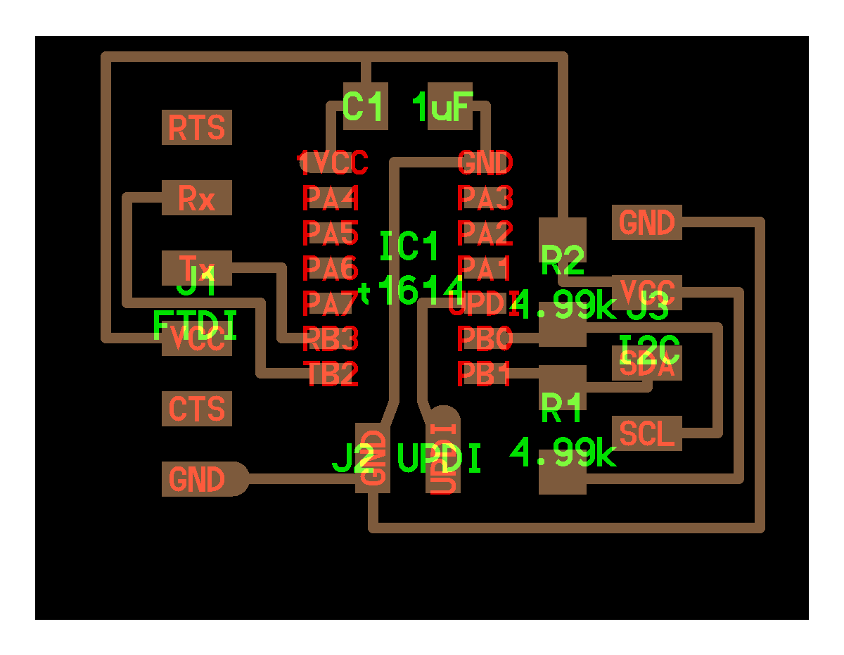
The boards:
I designed these with the intention of establishing a SPI library but things didn’t go to plan.
Schematics
PCBs
I2C Master-Slave Communication
Trying to get SPI to work was taking too long. Since I was a bit fluent in I2C I decided to try and get that to work.
I2C Pull-up Resistors
First I needed some pull-up resistors. Didn’t know what value I should use.
The Original specs recomend between 2kΩ-10kΩ.
Here’s the updated revision: I2C User Manual Rev7
If you’re wondering about the math there’s this:
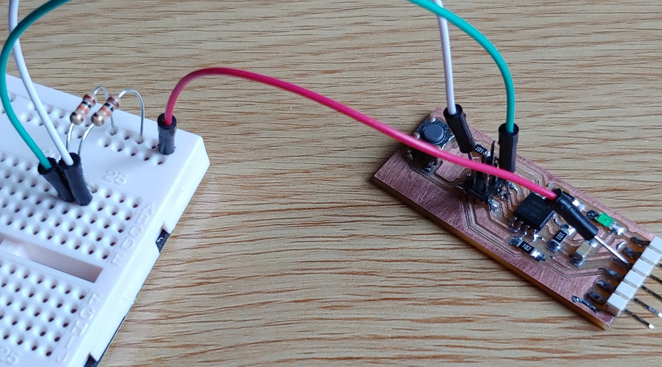
Here’s me Mcguyvering some pull ups into my I2C connection without female-male cables and before my solder arrived. This was during a weekend and I was in a hurry to try things lol
TinyWire Libraries
Aparently Old AtTiny series MCUs don’t support the regular Wire Library Problem with size or lack of hardware peripheral?
Datasheet says the tiny45V supports I2C with limitations
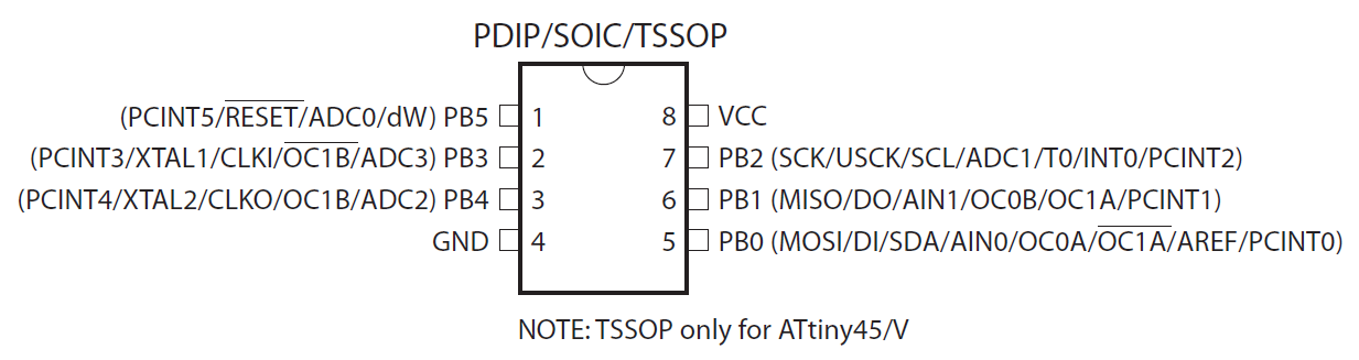
So I tried the TinyWire libraries.
There are a few different versions for both Master and Slave: Master1, Slave1, Slave2, rebuild of both.
I couldn’t get any of them to work. I’m sure I screwed up somewhere.
In any case use the search button, lots of other students have done great work. Both Katie, Ambroise, Cristiana, Rohan plus a lot more documented TinyWire working. I was probably too stressed and not thinking straight.
Bit Banging
Bit Banging is using software to make hardware do things it wasn’t setup to do. Like using I2C in MCUs or pins that didn’t support it from factory.
Here’s someone outputing a VGA signal from an ESP32
Or even more hardcore: Ethernet on a Tiny85!
He even got Duplex to work…
Here’s a talk he gives about LUTs, Look Up Tables. If I have the time I want to try and make one for my final project to skip some of the trig math.
Here’s a good .pdf on Bit Banging
Now I want to mention 2x bit banging i2c examples Neil has made:
One for a tiny44 interacting with a ADXL343
And another one for a tiny412 and a TLE493D
Registers
Registers are how software interacts with the physical pin hardware. A basic understanding is a pre-requisite for the next steps.
These helped me get a sense of how they work:
Port/Pin Names and Bitwise Operations
Getting back to the tiny44 and tiny412 code there’s a section we need to focus on. While we dont really need to understand how all of it works these snippets are vital.
On the tiny44
#define SCL_pin (1 << PB3)
#define SCL_pins PINB
#define SCL_port PORTB
#define SCL_direction DDRB
#define SDA_pin (1 << PB4)
#define SDA_pins PINB
#define SDA_port PORTB
#define SDA_direction DDRB
On the tiny412
#define SCL_pin PIN2_bm
#define SCL_pins VPORTA.IN
#define SCL_port VPORTA.OUT
#define SCL_direction VPORTA.DIR
#define SDA_pin PIN1_bm
#define SDA_pins VPORTA.IN
#define SDA_port VPORTA.OUT
#define SDA_direction VPORTA.DIR
Those #defines are what tells the code which pins we want the code to run on. Without understanding those we can’t re-use Neil’s code on other boards unless you assign the correct pins. Even changing micro-controller can be an issue as you’ll notice notation changes from one to the other. SCL_Pin goes from (1 << PB3) to PIN2_bm…
Took me quite a long time to understand this. Even had to ask reddit for help but I did get some useful pointers. Having someone to go back and forth is always great.
So what do they mean?
We can start with the easy part - the SCL_Direction and SDA_Direction have to do with the pins being set as input or output. Should be easy to find in the MCU’s datasheet.
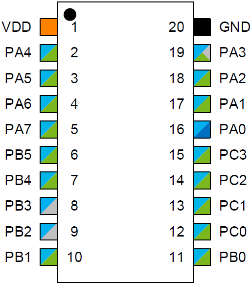
Next we have the Port registers. You’ve already had contact with this register. Pinouts always call pins by their full name and it includes which Port Register they belong to. PA3, PB0, etc. Just means they belong to the PORTA register or the PORTB register. Maybe even PORTC, PORTD and beyond if they have a lot of pins like the 20 pin versions of the Tiny322X controllers.
VPORTs like the tiny412 uses instead of PORTs seems to have to do with internal optimized addresses an MCU designer can add to speed up certain actions. No idea how they work, if they show up in the Datasheet you can try to use them I guess?! Read more about it here.
Now for the messy part. Why (1 << PB3) and PIN2_bm…
Even asking Neil directly proved I was in over my head lol But after a couple of answers and with reddit’s help I finally understood what the change meant. The notation used is set by the “package” or Core you’re using in your IDE.
Lets look at the tiny412 Core files that deal with the pins.
If you search for PIN2_bm in this file (This is the original URL but I’m afraid they might move it and break the link) you’ll find:
#define PIN2_bm 0x04
#define PIN2_bp 2
PIN2_bm represents a hexadecimal bitmask while PIN2_bp is just the int number for the pin. Now the link I had bookmarked with the tiny44 code is no longer active and I don’t think the new file is exatly the same, but the point is that PB3 also represents an integer.
The bitwise operation in the (1 << PB3) notation is transforming the int into the hex bitmask equivalent. We now know #define SCL_pin just wants a bitmask so it’s easier to use PIN2_bm when a pure hex bitmask is available the notation (1 << PIN2_bp) would also work.
Bitwise operations in general are very important for bit banging so you should read more about them if you want to go deeper.
Signal Modulation
Now that we’ve gone through how Bit Banging works at a more fundamental level we can go ahead and forget about I2C… Why ignore it after all this work? Because with what we know about Bit Banging we don’t need to use it. We can make our own protocol!
About halfway through figuring out the pin name notation it occured to me that I didn’t really need I2C. I was just turning LED’s on and off so what was the most basic way I could tell a second board to do just that. On top of that it was following a recuring sequence so I could get away with the most basic protocol possible.
Once I got the pin notation under control I mentioned to Neil what I was trying to do and he mentioned signal Modulation and how information is transmitted.
Here’s an example gif of how a signal is represented differently between AM and FM:
Honestly it’s a bit of a rabbit hole and I haven’t had time to really dive into it but at least it’s nice to know the technical terms of what I was trying to do.
At first I was considering something a long the lines of Line code. A stream of synchronized ups and downs of voltage to represent 1s and 0s. But I figured that would: A- need either an extra cable to represent signal timming or B - advanced code related to the integrated timers inside both MCU’s as to make sure they encoded and decoded the signals correctly. I looked into it breefly so here’s a good video:
Gave up on the idea because all this was taking a bit too much time and I also had the idea of writing the bit bang code in plain C/Arduino language so that anyone starting out wouldn’t be overwhelmed.
After a quick brainstorm I moved onto what’s essentially called Amplitude-shift keying. The voltage value is either a 1 or a 0. It’s up to the receiving part to figure out what to do. What I had in mind is specifically called On–Off keying.
The actions I had on the LED board was simply a table of instructions within a Switch() logic check. It was also both sequential and in only one direction. While my boards are only turning LEDs on and off this could be used for more advanced functions as long as they are sequential.
My protocol is nothing more than a digital button at this point. I’m just pressing a virtual button with one MCU when I physically use my finger on the button board. It uses just 2 wires, ground and signal. If we add a 3rd signal wire it would be easy to add more advanced functions like a timming frequency or just another virtual button so that the sequence order could be inverted. As in one virtual button moves the switch counter forward like the other moves it back. It could be used for simple functions like changing images/sounds or moving motors in predictable animations.
I re-used the single button counting loop I had already used previously and adapted it to both sender and receiving boards. There’s a 50 milisecond delay on the SendImpulse() function to make sure the digital presses were read on the receiving board. I’m sure this could be fine tuned into lower values.
Here’s a clip of it almost working:
I wanted to write the switch cases in a more efficient way that a signal was only sent when there was a change to the LED status on the receiving board but it was late and I didn’t feel like putting more time into it.
Here’s a clip of the code working.
LED + Button
// constants won't change. They're used here to set pin numbers:
const byte buttonPin = 4;     // the number of the pushbutton pin
const byte ledPin = 3;      // the number of the LED pin
const byte dataPin = 1;
const byte commandPin = 0;

// variables will change:
byte buttonState;          // variable for reading the pushbutton status
byte buttonCounter = 1 ;       // variable for counting button presses
byte lastButtonState = LOW;

void SendImpulse(byte cycle){
  for(byte counter = cycle; counter < (cycle*2); counter++){
    digitalWrite(dataPin, LOW);
    delay(50);
    digitalWrite(dataPin, HIGH);
    delay(50);
    }
}

void setup() {
  // initialize the pushbutton pin as an input:
  pinMode(buttonPin, INPUT);
  // initialize the LED pin as an output:
  pinMode(ledPin, OUTPUT);
  // initialize the LED pin as an output:
  pinMode(dataPin, OUTPUT);
}

void loop() {
  // read the state of the pushbutton value:
delay(25); //debounce?
buttonState = digitalRead(buttonPin);
  if (buttonState != lastButtonState){
    if (buttonState == HIGH){
      switch (buttonCounter){
        case 0:
          digitalWrite(ledPin, LOW);
          //SendImpulse(buttonCounter+1);
          SendImpulse(1);
          buttonCounter++;
          break;
        case 1:
          digitalWrite(ledPin, HIGH);
          SendImpulse(1);
          buttonCounter++;
          break;
        case 2:
          digitalWrite(ledPin, LOW);
          SendImpulse(1);
          buttonCounter++;
          break;
        case 3:
          digitalWrite(ledPin, HIGH);
          SendImpulse(1);
          buttonCounter++;
          break;
        case 4:
          digitalWrite(ledPin, LOW);   // turn the LED on (HIGH is the voltage level)
          SendImpulse(1);
          buttonCounter++;
          break;
        case 5:
          digitalWrite(ledPin, HIGH);
          SendImpulse(1);
          buttonCounter++;
          break;
        case 6:
          digitalWrite(ledPin, LOW);
          SendImpulse(1);
          buttonCounter++;
          break;
        case 7:
          digitalWrite(ledPin, HIGH);
          SendImpulse(1);
          buttonCounter=0;
          break;
      } // MAIN CYCLE
    } // BUTTON STATE
  } // BUTTON PRESS
  lastButtonState = buttonState;
}
LED + LED
// constants won't change. They're used here to set pin numbers:
const byte ledPin1 = 3;     // the number of the pushbutton pin
const byte ledPin2 = 4;      // the number of the LED pin
const byte dataPin = 1;
const byte commandPin = 0;

// variables will change:
byte pulseState;          // variable for reading the pushbutton status
byte impulseCounter =0;       // variable for counting button presses
byte lastPulseState = HIGH;

//void SendImpulse(byte cycle){
//  for(byte counter = cycle; counter < (cycle*2); counter++){
//    digitalWrite(dataPin, LOW);
//    delay(10);
//    digitalWrite(dataPin, HIGH);
//    delay(10);
//    }
//}

void ReadImpulse(){
  pulseState = digitalRead(dataPin);
  if (pulseState != lastPulseState){
    if (pulseState == LOW){
      impulseCounter++;
    }
  } // ON PULSE
  lastPulseState = pulseState;
}

void setup() {
  // initialize the pushbutton pin as an input:
  pinMode(dataPin, INPUT);
  // initialize the LED pin as an output:
  pinMode(ledPin1, OUTPUT);
  // initialize the LED pin as an output:
  pinMode(ledPin2, OUTPUT);
  // initialize the LED pin as an output:
}

void loop() {
//  ReadImpulse();
  switch (impulseCounter){
    case 0:
      digitalWrite(3, LOW);
      digitalWrite(4, LOW);
      ReadImpulse();
      break;
    case 1:
      digitalWrite(3, LOW);
      digitalWrite(4, LOW);
      ReadImpulse();
      break;
    break;
      case 2:
      digitalWrite(3, LOW);
      digitalWrite(4, HIGH);
      ReadImpulse();
      break;
    case 3:
      digitalWrite(3, LOW);
      digitalWrite(4, HIGH);
      ReadImpulse();
      break;
    case 4:
      digitalWrite(3, HIGH);
      digitalWrite(4, LOW);
      ReadImpulse();
      break;
    case 5:
      digitalWrite(3, HIGH);
      digitalWrite(4, LOW);
      ReadImpulse();
      break;
    case 6:
      digitalWrite(3, HIGH);
      digitalWrite(4, HIGH);
      ReadImpulse();
      break;
    case 7:
      digitalWrite(3, HIGH);
      digitalWrite(4, HIGH);
      ReadImpulse();
      break;
    case 8:
      impulseCounter=0;
      break;
    break;
  } // SWITCH
} // LOOP
Files
2x Tiny45 COM Boards - Both Need a Makeover