
Week 03. Computer-Controlled Cutting
This week there are two types of assignments; one group and one individual. As I am alone in my Fab Lab I will do both.
Here are the Assesment Criteria of this Assignment.
- Laser Cutting:
- Characterize your lasercutter's focus, power, speed, rate, kerf, and joint clearance. ✔
- Design, lasercut, and document a parametric press-fit construction kit, which can be assembled in multiple ways. Account for the lasercutter kerf. ✔
- For extra credit include elements that aren't flat. ✔
- Vinyl Cutting:
- Cut something on the vinylcutter. ✔
- Linked to the group assignment page. ✔
- Explained how you parametrically designed your files. ✔
- Documented how you made your press-fit kit. ✔
- Documented how you made your vinyl cutting. ✔
- Included your original design files. ✔
- Included your hero shots. ✔
- Model: Epilog Mini 24 Laser 40 W CO2.
- Software: Rhinoceros + Driver of Epilog
- Work area: 610 x 305 mm
- Maximum material thickness: 139.7 mm or 203 without plate or rack
- Settings:
- Corrugated cardboard:
- Vector: Power: 80% / Speed: 100% / Frequency: 457 Hz ppi 400
- Raster: Power: 70% / Speed: 70% ppi 400
- DM 3mm:
- Vector: Power: 90% / Speed: 15% / Frequency: 5000 Hz ppi 400
- Raster: Power: 90% / Speed: 50% ppi 400
- Superficial Vector: Power: 50% / Speed: 100% /Frequency: 5000 Hz
- Acrylic 3mm:
- Vector: Power: 90% / Speed: 7% / Frequency: 5000 Hz ppi 400
- Raster: Power: 90% / Speed: 50% ppi 400
- Superficial Vector: Power: 50% / Speed: 100% /Frequency: 5000 Hz
- Corrugated cardboard:
- DM 3 mm:
- Outside (Large) 10.25 mm
- Inside (Small) 9.9 mm
- Acrylic 3 mm:
- Outside (Large) 10.25 mm
- Inside (Small) 9.7 mm
- Parametric Design in Fusion 360
- Parametric Design in Step
- Rhinoceros File.
- Parametric Desgin and Press-fit test of cardboard in SVG.
- Software: Rhinoceros + Driver of Roland
- Maximum cutting area: 584 x 24998 mm
- Cutting speed: 10-50 mm/s
- Settings:
- Textile Vinyl: Speed: 15 cm/s / Force: 90gf
- Copper Vinyl: Speed: 1 cm/s / Force: 40gf

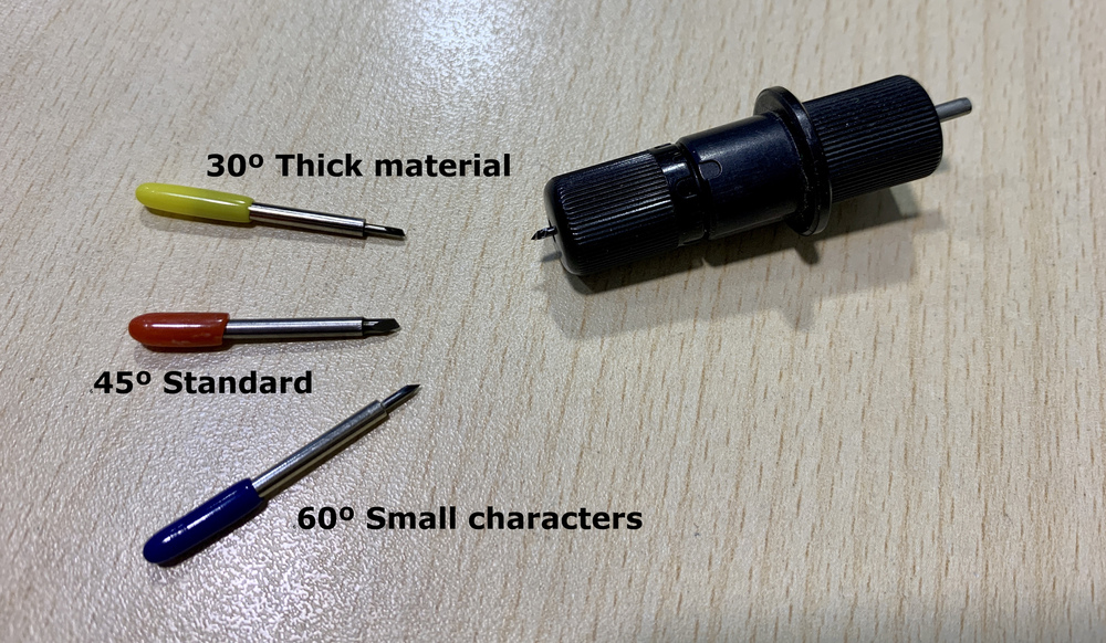
- For thick material cuts, 30º yellow blades are used.
- For standard cuts of calendered and cast vinyl, 45º blades of red color are frequently used.
- For cutting materials for thermal transfer, sandblasting mask, magnet or for cutting small characters, the 60º blades of blue color are used.
- Software: Silhoutte Studio 4.3
- Maximum cutting width: 305 mm
- Cutting force 5 kg
- Settings:
- In the menu of Silhoutte Studio when choosing the default material loads parameters for the automatic knife.
Like every week, my weekly schedule. 😊

Group Assignment
The Group Assignment page is at the following link.
Laser Cutting
Laser cutter
The laser cutter that exists in the Fab Lab León is the following model.

When I discovered the laser cutter at the Fab Lab León, a box of surprises opened. It is a fast machine, which allows you to perform projects very quickly and combine different materials.
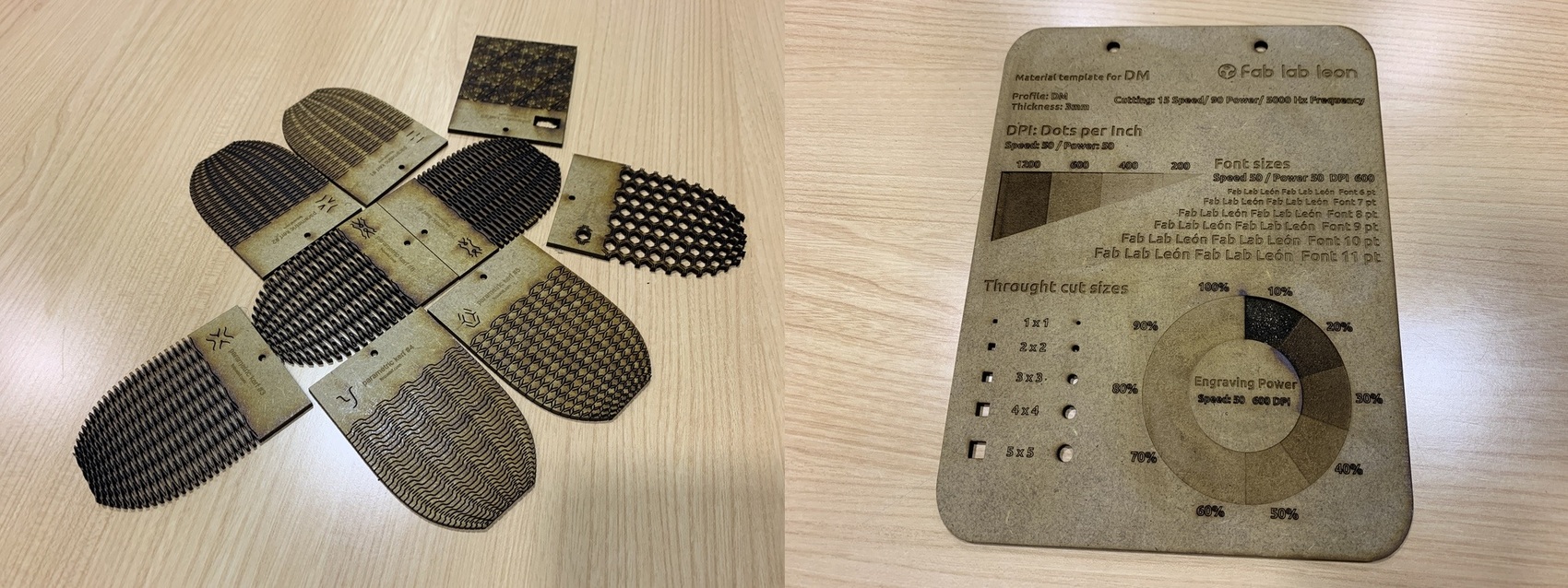
Last year during the summer I made several samples to teach during the OpenLab conference and show the public what possibilities the laser cutter has. The Curved Laser Bent Wood sample download it from Instructables and the values test for the different materials creates it following one that I saw on Instagram (If someone wants it, ask me. There are many megabytes for my repository).
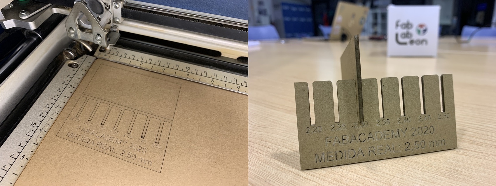
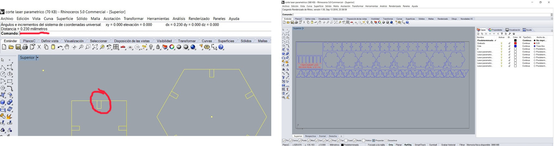
The first thing I need is a press-fit test for corrugated cardboard. For this I design with Rinoceros a template with several lace to different sizes. The actual measurement of the carton with the caliber is 2.50 mm. In the Fab Lab León there is a notebook where the parameters of the materials we use in the laser are documented. In it I found the following parameters for corrugated cardboard of 2 mm. Vector: Power: 80% / Speed: 100% / Frequency: 457 Hz ppi 400 - Raster: Power 70% / Speed 70% ppi 400. This can serve as an estimate, you always have to perform tests, because the materials can influence the material, cleaning of the machine and its condition.

Once the test is cut, I test the fit that best fits, deciding the value of 2.30 mm that I will then use in the parametric design.
Kerf: 2,50mm (real measure of the cardboard) - 2,30mm (real pressfit) = 0,20 mm kerf of cardboard
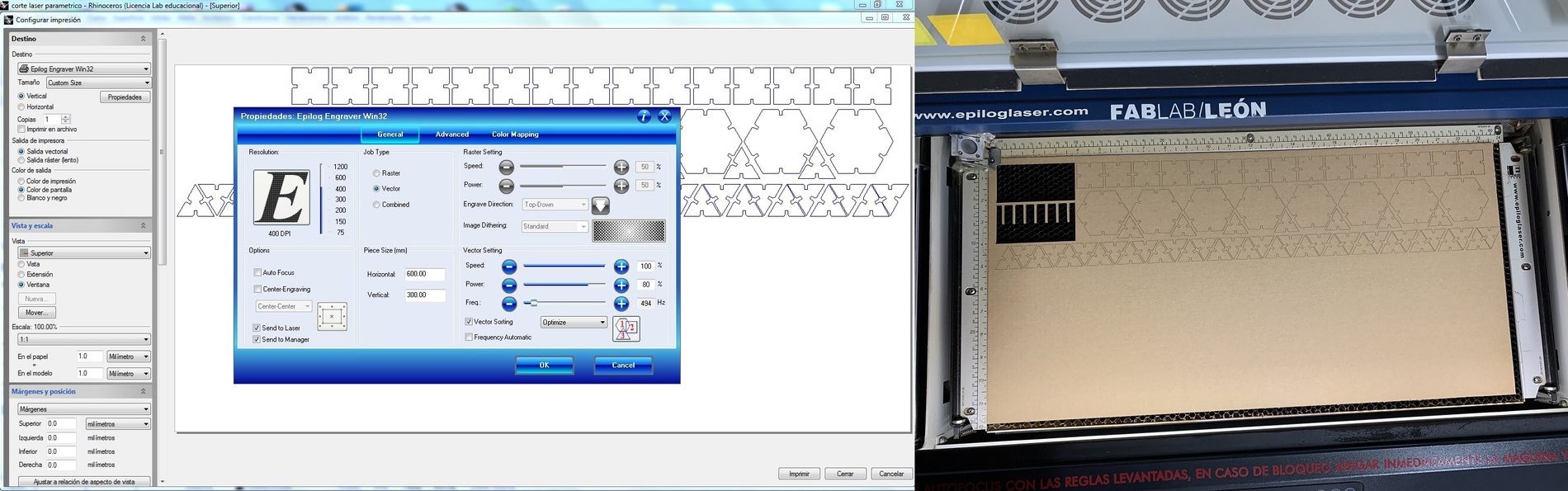
After having performed the press-fit test for corrugated cardboard, I decided to do a kerf test for various materials and of small size as a sample. I design it with Rhinoceros, and in the test I will have a 10 by 10 mm square to check the measurements with the caliber, and a scale of rasters at different power percentages and the vector parameters. For this I use the color mapping function in the laser software to make different rasters in the same process, changing only the parameters and assigning a color to each layer.

Here the final result of cutting and rastering DM of 3 mm with two different rastering values and Acrylic of 3 mm. Sorry for the lack of acrylic spelling with "i". 😬
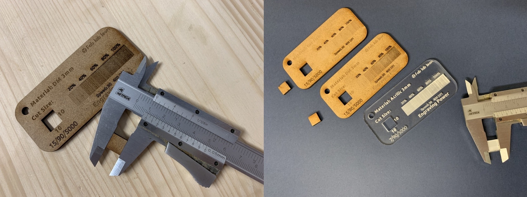
Short in DM of 3 mm and acrylic of 3 mm transparent. The 10 x 10 mm square designed has become the following measures.
A small accelerated video of how I perform one of the tests.
And as Neil says well and Nuria has taught me, the laser cannot be left unattended. Also a very important phrase when you use the laser cutter is, "Measure twice, cuts one". Every time the work is finished, you have to clean the rules, the bee panel and every so often clean the lens. The extraction of the gases is done outside, but the proper functioning of the extractor and the compressor for the air assist must also be checked.

Parametric Design with FreeCad
I have never used the parametric design. I almost always measure the material and do a couple of tests on the laser cutter and adjust the complete design to that material. With the parametric design it is easier, but at the same time complicated because you have to create mathematical formulas, constants and rules so that the design is not neglected.😵
Watching the videos of Neil in class and others on YouTube, I decided to try the parametric design with Freecad. By means of the Sketcher and the Spreadsheet (value table) I begin to design a simple piece, a square with several laces and also rounded corners. At the moment that I start to insert the values in the table, some pieces move, the parallels are not fulfilled and that I have marked different constraints.
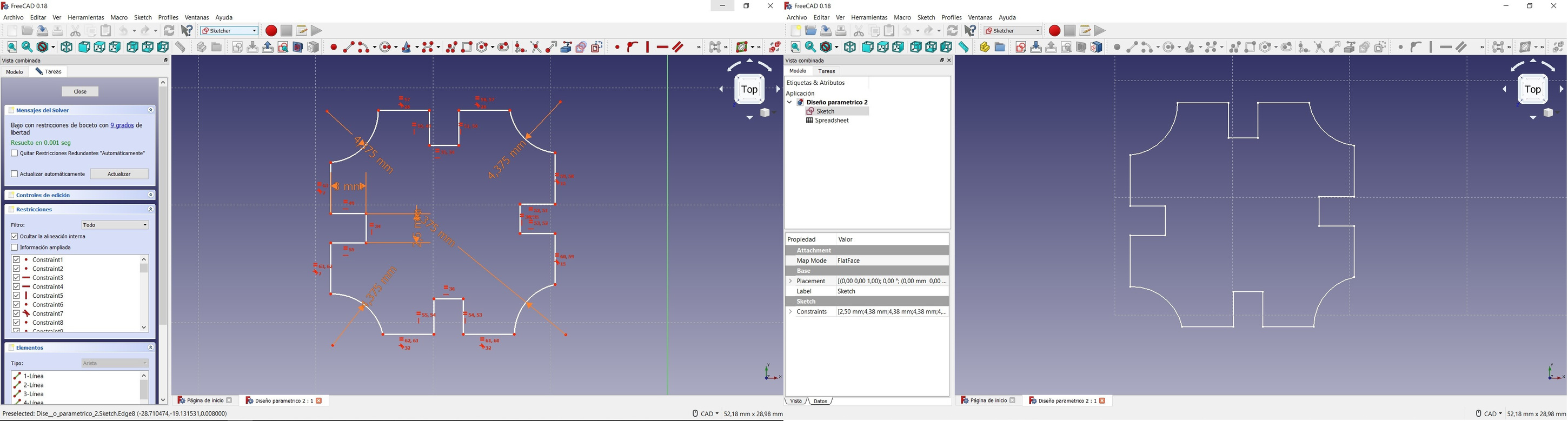 I am not comfortable 😔, it does not convince me how it looks so I choose to try Fusion 360. However I leave here the test file.
Parametric Design with Fusion 360
Last week, I discovered Fusion 360. In the design section there is a tab that allows you to create a value table. Within this value table you have to create the variables within "User Parameters" (you need a name, the units, the expression or mathematical formula and finally the value of that formula will appear). Once the value table is filled (calm, you will surely create more variables throughout the design), I begin to draw a sketch with the desired shape. I start with a square with four lace.
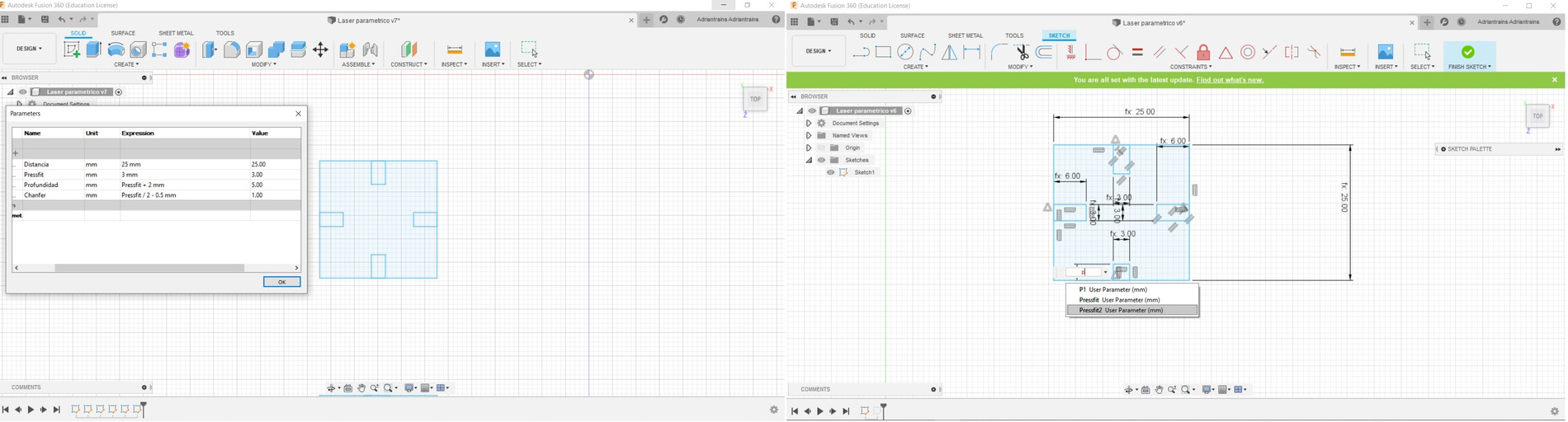
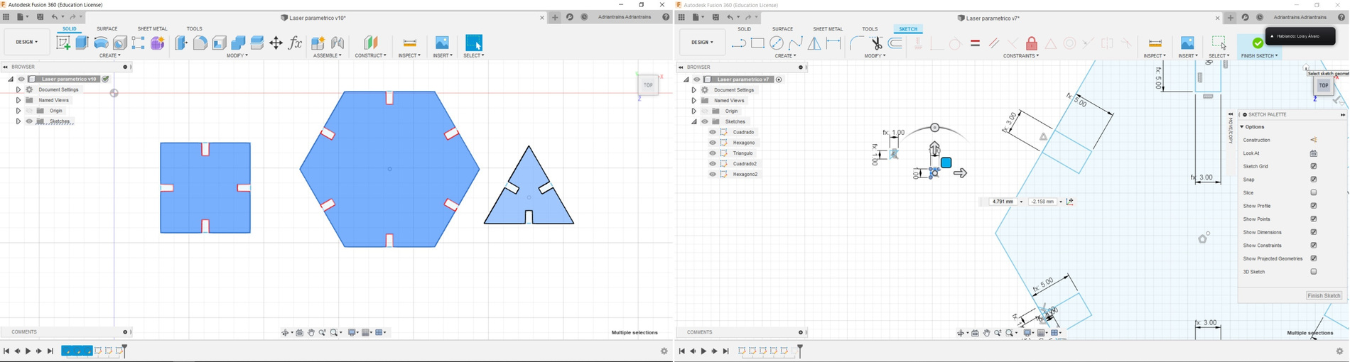
After getting a square 😅, I continue and try to make a hexagon and a triangle. It is very important to use the constraints; there is the Midpoint to place the pieces at the midpoint of a line, but you also have to use the tool to place the pieces perpendicularly. If you don't use it, everything will be checked when you start modifying the variables in the table.😣
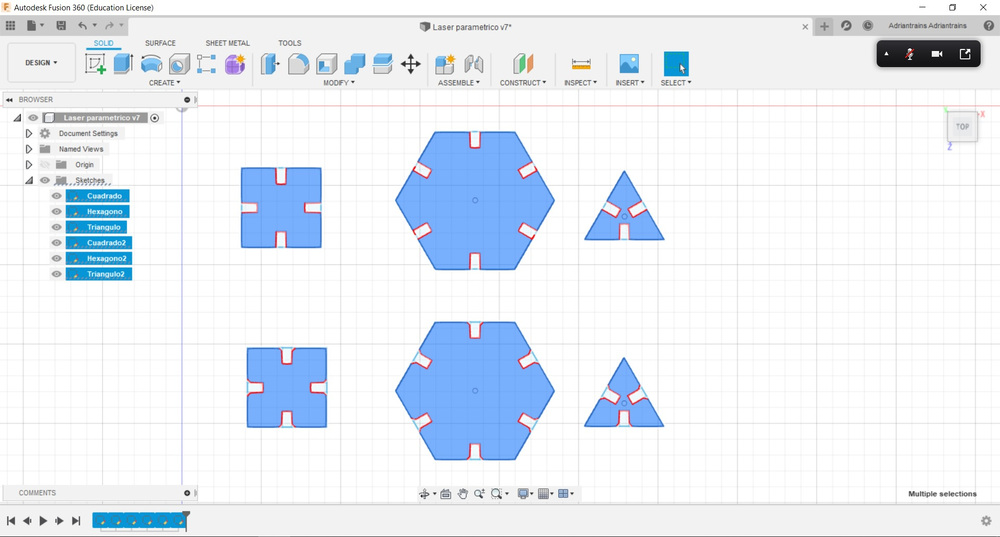
Well, this seems to be improving. I have managed to create a rectangle, a hexagon and a triangle that vary using the parameters I enter in the table. Neil commented in class that to favor the union of cardboard pieces it is advisable to make chamfer in the lace. So I make some small triangles that are going to be my chamfer (I had only discovered the fillet command, then I found the chamfer one). 😂
This is the final result, with the comparison of an object with and without chamfer. To use this design in the laser, I need to save the file in .DXF format to be able to open it in Rhinoceros which is the software we use to make the cuts and rastering.
Laser Cutting + Rhinoceros
As I have done the Press-fit test on the 2 mm cardboard and I have proven that the value fits better to perform better press-fit, I have chosen the 2,30 mm value that I enter in the variable table. When I import the .DXF into Rhinoceros, something strange happens to me, the pieces are very small, smaller than the Kerf test. I measure the distance of a lace and see that it measures 0.23 mm and the real one is 2.3 mm. Apparently Fusion 360 when you export the file in DXF scales the size of the pieces. Once the problem is solved, I clean the design of auxiliary lines that appear in the DXF. I prepare the design for the cardboard plate where I had cut the Kerf test before. I will cut several pieces to make an assembly.
For the cutting of the 2 mm cardboard, change the frequency parameter by increasing it a little to benefit that there are no small dashed lines and it is difficult to remove the pieces from the plate. I use 100% speed, 80% power and 494 frequency.
Once the pieces have been cut, it is necessary to separate them from the base and verify that they work.
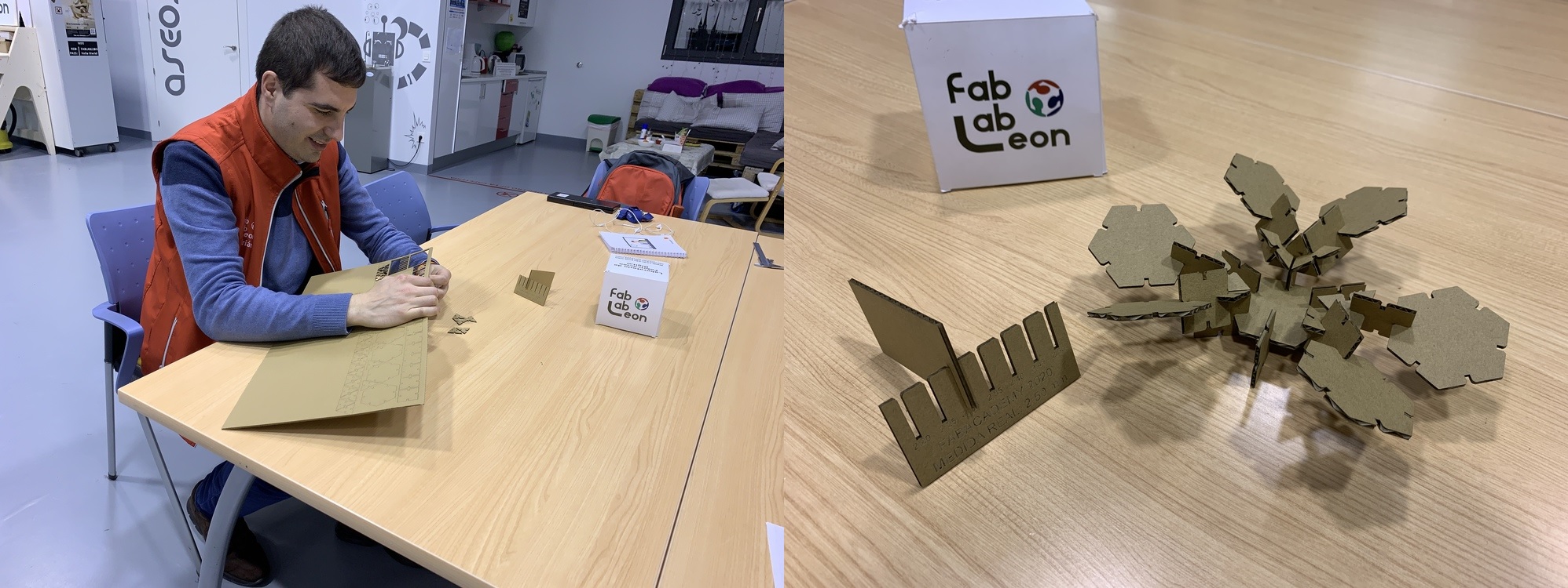
I left the pieces to my sister and she created the Puppy-Dino 🐕

Bend acrylic with the lasser cutter
During the class Neil showed us the LaserOrigami page and I thought it was incredible. In the Fab Lab León we have some plates similar to those used to straighten the hair that heats the acrylic and fold it wherever you want. I have never tried to bend acrylic with the laser so I got down to work.😵
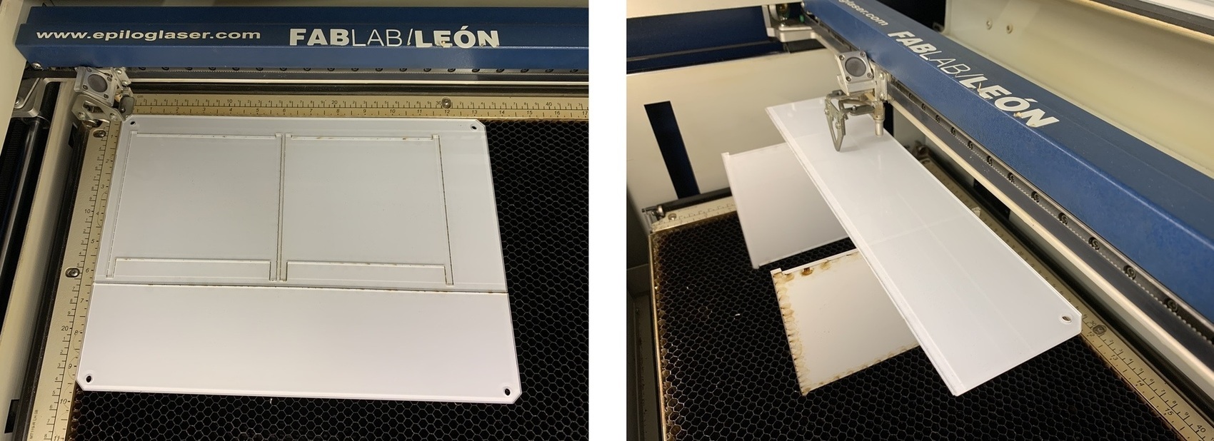
The first thing I need is a "bridge" to raise the acrylic over the laser bee panel. For this I use the same material, acrylic and I make two small legs to hook the panel and it is perpendicular. I design it in Rhinoceros and I cut it with the laser. The leftover acrylic is the one I'm going to use to do several tests.
Now I am going to cut a small square of 30 x 30mm minus one of its sides, where that side will be where it will bend. I start the tests by placing several lines offset to 0.1 mm at the point that is bending and defocused the laser 10 and 20 pulses down (Z axis) and the same power as the cut-off 90% Power, 7% Speed and 5000 Frequency. The offset does not work, just cut the piece.
This is trial and error test. I try to make a frame of raster by making three passes at 13 Power and 90 Speed. Neither. So discarded the lag of lines and the rastering oor plot I reread the documentation of the page and watch a video on Youtube .
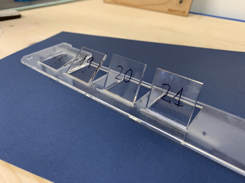
In the documentation account that makes 20 passes on a single line and defocused the laser. So in the design I create 20 lines and blur the laser 40 points down and with the parameters 30% of Power, 30% of Speed and 5000 of Frequency. I observe that the focus of the laser is more diffuse and begins to melt the material, but it ends up falling. So I try to blur the laser more, up to 60 points down and I'm doing 10 in 10 lines. When I made line 18 ¡¡ EUREKA !! the acrylic is bent. I perform more tests, with 19, 20 and 21 lines respectively. Same parameters. Normal cut 90% of Power, 7% of Speed and 5000 of Frequency. Cut for Bending 60 points of defocused in the laser and 30% of Power, 30% of Speed and 5000 of Frequency.
First spiral achieved, I liked it but I want to keep trying. 😅 In the YouTube video they create a pen-holder; I design my own with two circles joined by a rectangle, the two circles have to be at 90º with respect to the rectangle. With the same parameters I had used for the square, I started to create the portabolis; but to the past 19 a circle is broken. 😖 The other circle makes only 18 lines and remains. To try again with only 18 lines and it comes out perfect. 😊
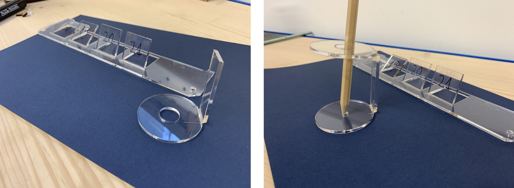
Now that I have realized that it depends on the size of the piece that we want to double, how many passes must be taken on the line. My recommendation is that you give 10 passes and then, two by two, increase until you see the final result.
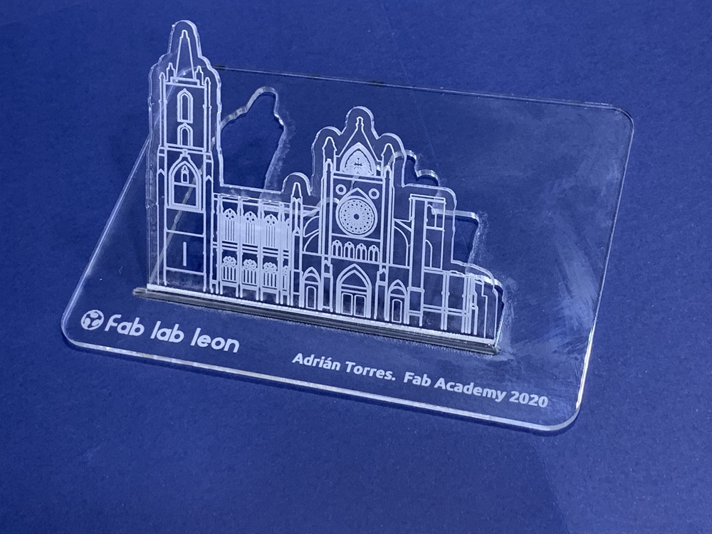
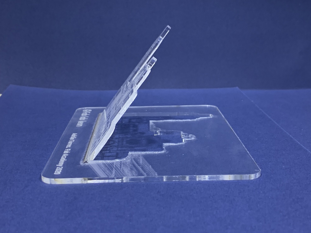
As I liked this technique very much, I decided to create a decorative outline of my city, the Cathedral of León. I have rastered the Cathedral and I have cut its outline. Then I have given 18 passes to fold the piece to my liking. I leave you a small video of the end of the folded.
I am very proud of the result. 😍😍
Here the links to the design.
Vinyl Cutting
Vinylcutter
In the Fab Lab León there are two vinylcutters:.
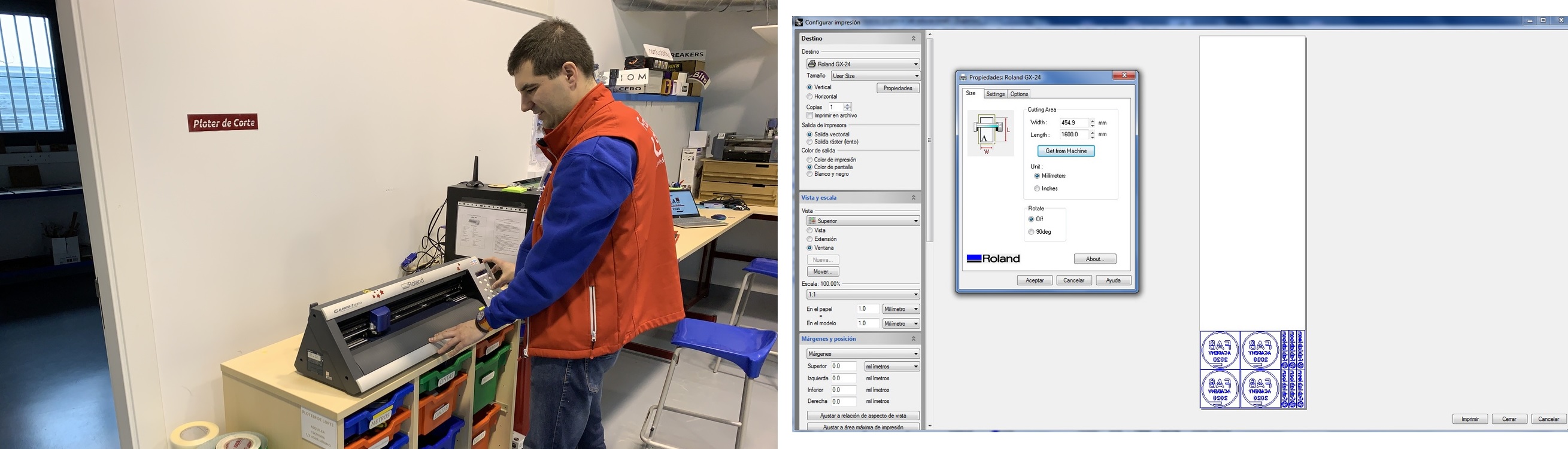
ROLAND GX-24.The Roland vinyl cutter has the advantage that the blades can be changed depending on the work to be done. The angle of the cutting blades is a factor to consider. The most common angles are 30º, 45º and 60º.

T-shirt with textile vinyl with the Roland GX24
The vinyl cutter is the sticker machine as the Poderosas of the Fab Lab León say, but many things can be created. I have to say that at the beginning, when I started using it for me it was the "love / hate" machine because either it fits me perfectly or my vinyl breaks. 😅
I will create my shirt that I will wear to the Fab16 to be held in Montreal. For this I will use the Fab Academy logo. I use Inkscape to vectorize the logo, then import it to Rhinoceros where I redesign part of the letters and numbers.
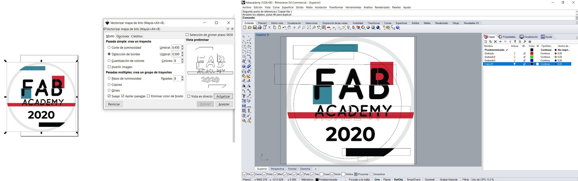
Once I have designed it I make the cutting of colors, in my case I will use three to make the composition and some will go on top of others. IMPORTANT: If you use textile vinyl, you should put the design in a mirror, otherwise when ironing it will be reversed.

When I have the design ready, I load the vinyl into the vinyl cutter. When you close the tab, it asks if it is "Roll"or "Piece" and depending on that measures the size. From Rhinoceros with the Roland driver, I give it to print and I get a tab with the characteristics of the machine. As the machine has measured the material there is, click on the Get from the machine button to know what measures there are of material. This will help us readjust our design to the existing material.
Now play the part of removing the vinyl that we do not want from our design, if we had small letters or dots we must be careful when removing the vinyl to not lose them. I will make three shirts, for my Instructors Nuria and Pablo and for me. 😍

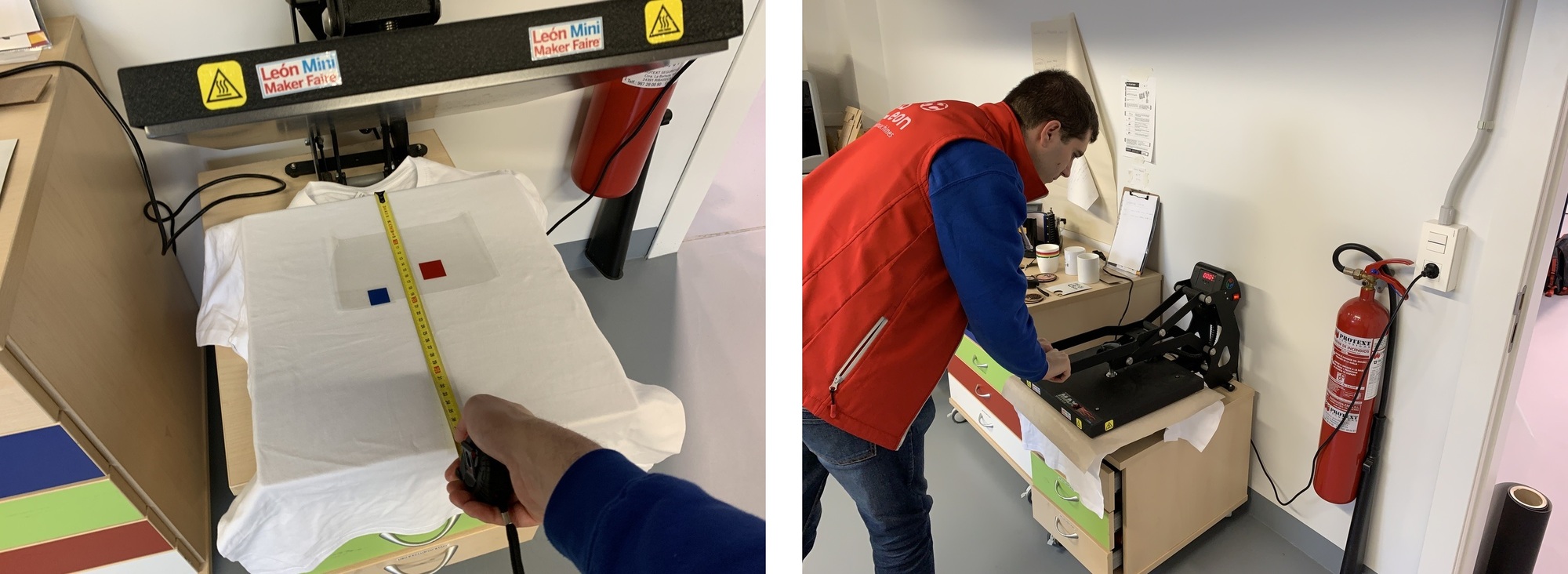
Then it touches the iron, for this I set it to 167ºC and 17 seconds of compression time. You have to be careful, because this design combines three colors and you have to overlap them on top of each other. I wear size L shirts and adjust the center of the shirt to the iron.
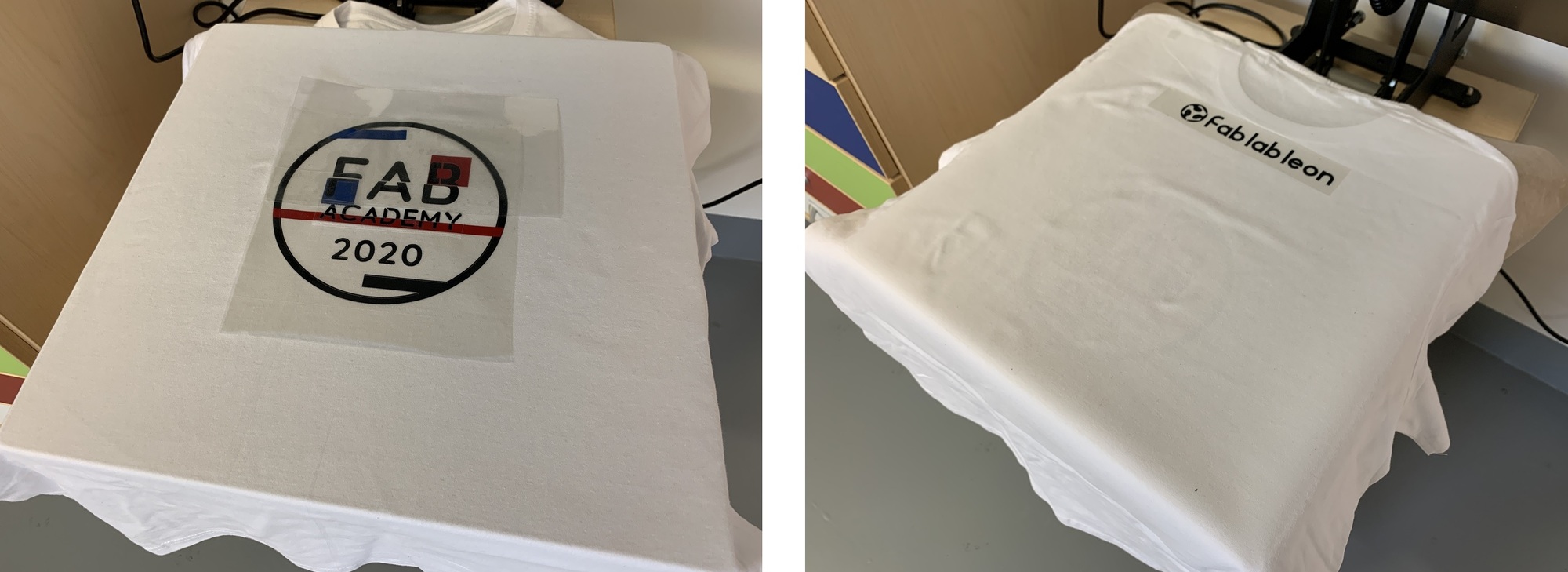
And here the final result. You will see it in Canada. 😍

T-shirt of Fab Academy 2021
13/02/2021
This year, although I´m an instructor, I wanted to design the T-shirt with the Fab Academy 2021 logo. This logo designed thanks to Miriam, and shared by Norella to carry out the communication campaign, I have vectorized through Inskcape and retouching the fonts with Rhinoceros .
We will need a blue t-shirt, white vinyl, turquoise blue vinyl, and red vinyl. I cut the entire white piece, and red and turquoise blue only the 1 and 0. In case you don't know, the ones and zeros mean 2021 in binary. The ones are turquoise blue and the zeros are red. I do the assembly, using white as a template and I layer the vinyl so that I only iron once.
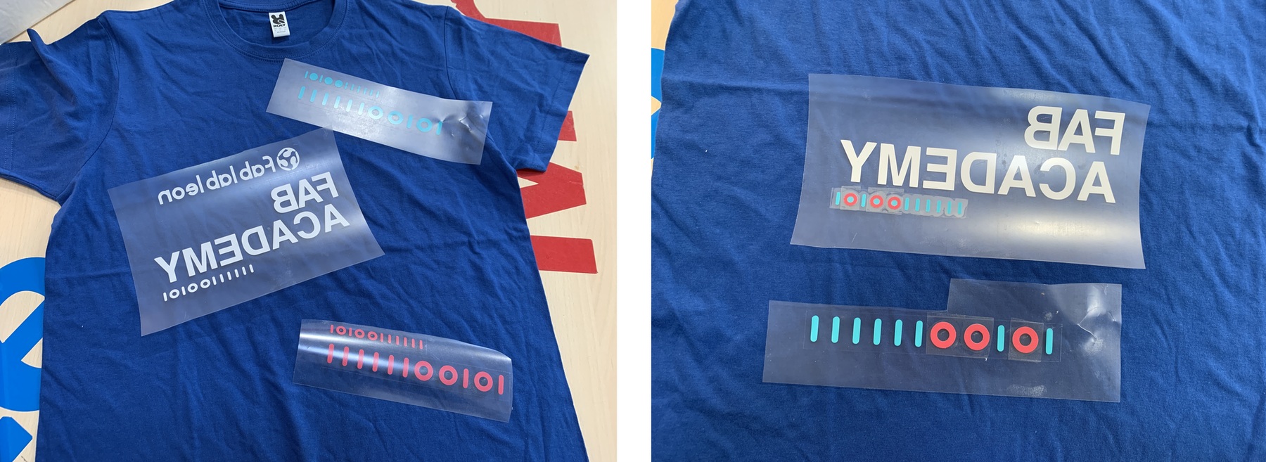
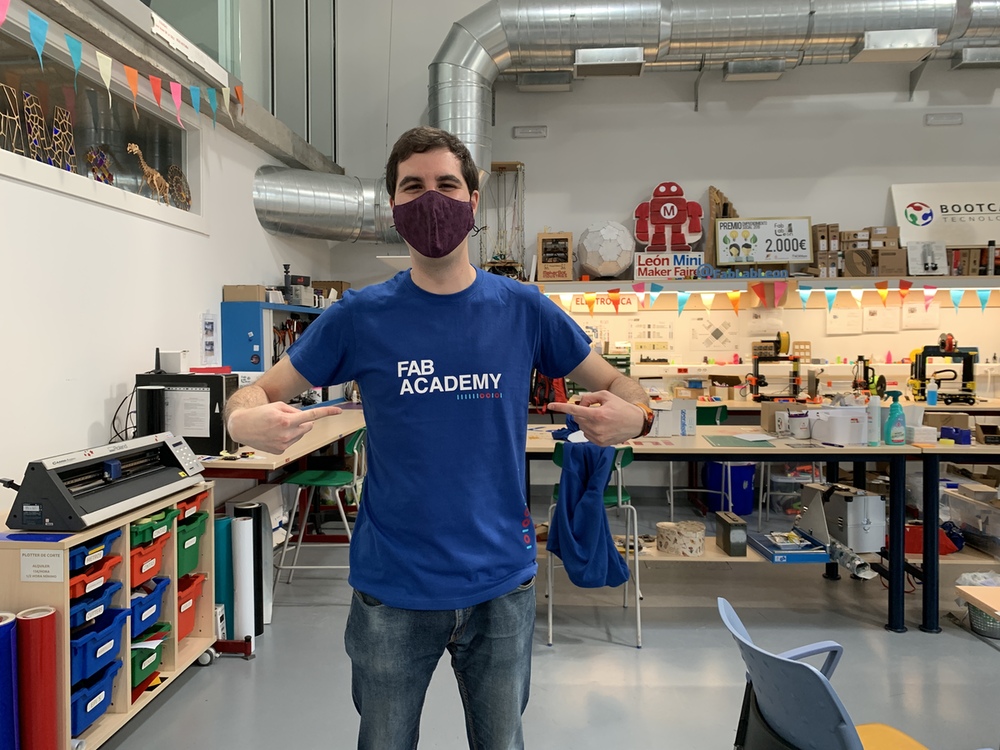
And this is the result. If you want the design click here or at the bottom of the page you can find the design.
Inflatables
During the review of this class, my instructor Nuria told me that I could try to create inflatables as she did during the Fabricademy. Thanks to Nuria´s documentation 😍 and Anastasia Pistofidou, Cecilia Raspanti and Fiore Basile for bringing digital manufacturing applied to textiles.
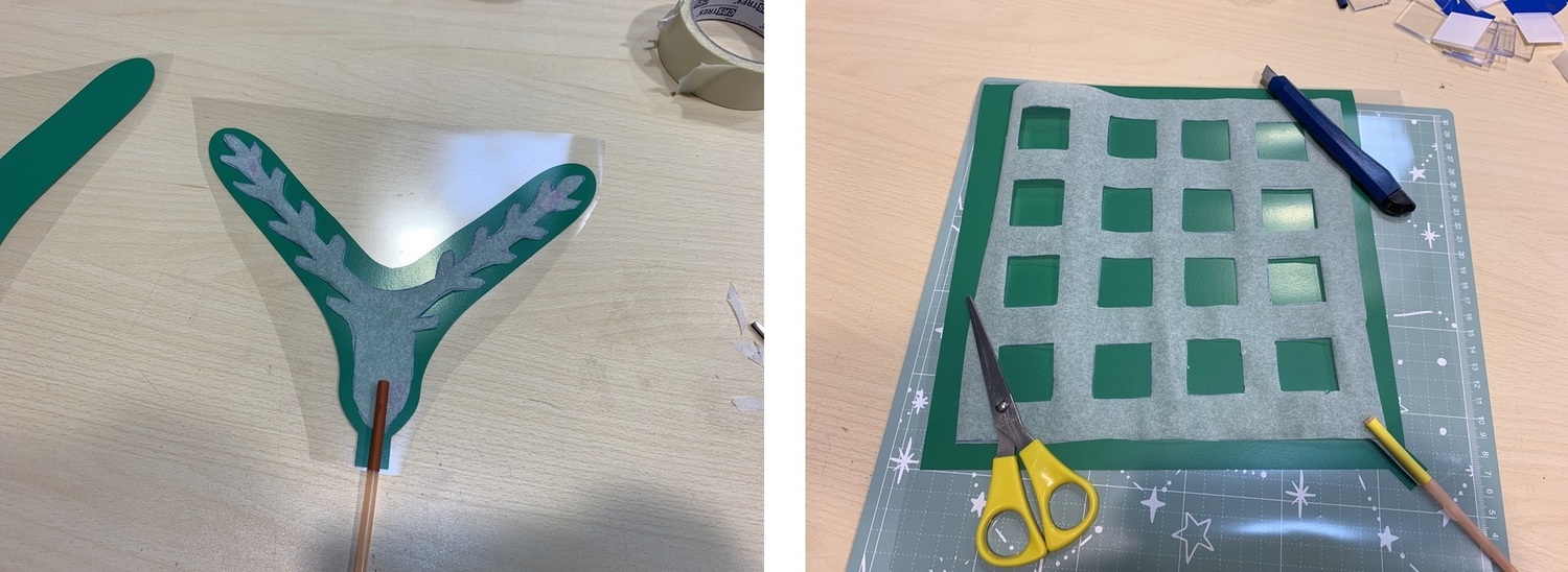
With Rhinoceros I create two different designs. Each design needs its same reflected piece, in order to join the two pieces. The inflation zone must be added to a corner or side. To inflate it, I am going to use a straw and the size of the straw must be offset to create a border around vinyl, to seal it so that the air in the inflatable does not escape.

Once the vinyl is cut and peeled, with baking paper I make the inner silhouette that I want to swell so that both parts of the vinyl do not stick. I have done this work by hand, painting first and cutting it out by hand; Surely I could cut it with the laser but sometimes it's not worth it. 😜

When I have the two baking paper templates, I put the straw and put a piece of heat shrink so that the straw does not melt and can not inflate the inflatable. RECOMMENDATION: You can iron it with a house iron or the same that I use for the shirt, but try to leave the straw out of the iron.
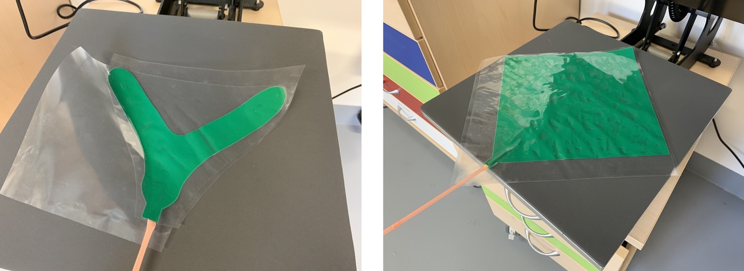
And here the result in video. My lungs are a little rusty. 🤣🤣
Here I leave the design in SVG.
Vinyl copper. Hello ATtiny 412.
23/02/2020 In Week 04 I worked with Copper Vinyl.
Sticker with Silhoutte Cameo 4
The Cameo 4 is a very compact and easy to transport machine. In the Fab Lab León we have it to make stickers with the little ones and in addition to reusing small vinyl cuts that come out of the Roland.
Its operation is very simple, it goes through its Silhoutte Studio software. You import an image or DXF, (it doesn't support PDF, or SVG a shame). Once you have the image in the size you want, you must hit the trace button (butterfly-shaped). You select the way to plot. You can draw the outer or inner contour or both; It will turn red. Then in the send button to the machine a menu appears where we will choose the tool (if we want to cut or only the outline) and the type of material, in this case Matte vinyl. As it has a self-adjusting blade, it automatically picks up the default material values and loads them into the machine. In this case 10 pressure and 5 speed.
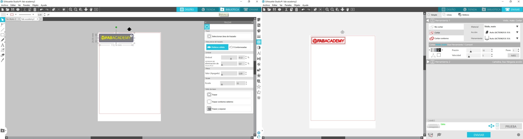
One of the advantages of Cameo 4 is that it can be used without a mat to place the materials to be cut.
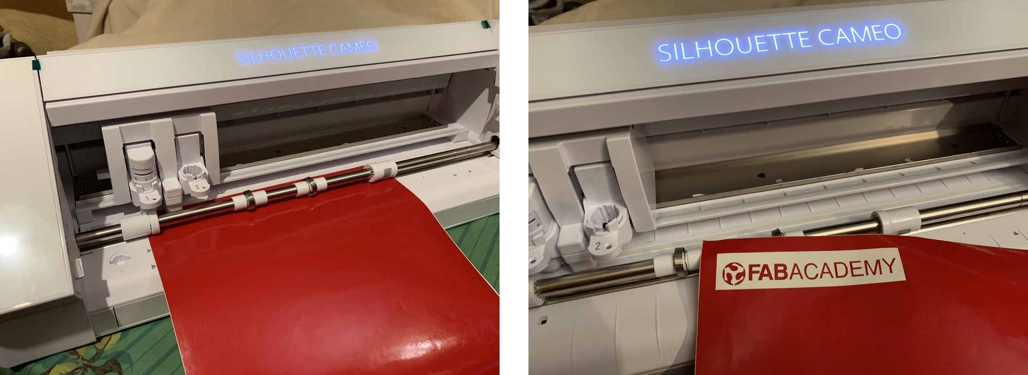
I already have a new sticker for my laptop. The Cameo is very simple to use, but limits the user's options. Automatically vectorizes the program, if you bring a DXF sometimes you do not see all the cut lines ... For someone who starts in the world of vinyl is very good or even for children.
17/02/2020: I have tried using Mods in Windows for the Cameo and I have not succeeded.

Extra credit
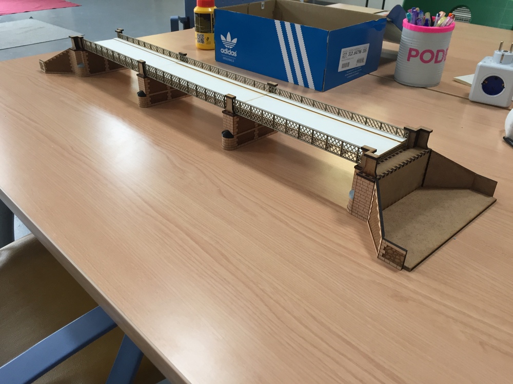
Use of digital manufacturing for model.
In 2015 I discovered the Fab Lab León and I started to apply all the digital manufacturing techniques that Nuria and Pablo have taught me. I have to be grateful to them for the incredible evolution that has taken place in me, I didn't know how to design anything and suddenly I create impressive things like this.
Last year a friend asked me to do the old Station Bridge that linked the center with the train station in the city of León. Here you can see an old photo.
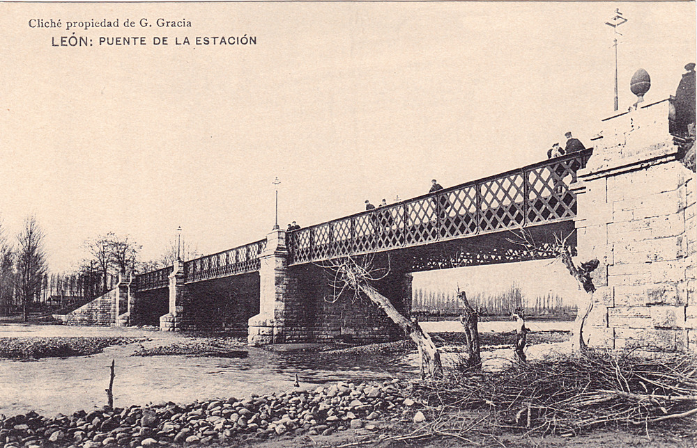
Using photographs and a plan of a railway bridge very similar to the one in the photo, I started to trace and design the bridge. Using Rhinoceros, design all the parts, in addition to combining the use of the Makercase platform to cut everything with the laser. Using the 3D printer, design circular pieces that topped the bridge pillars. The materials I used were DM of 3mm, paspartu (hard cardboard used in paint paintings), cardstocks and a very fine wood that has a paper that allows bending.
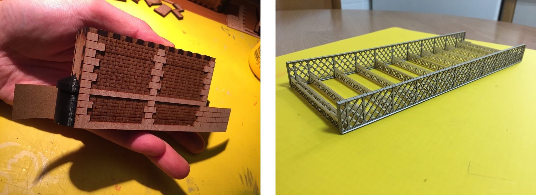
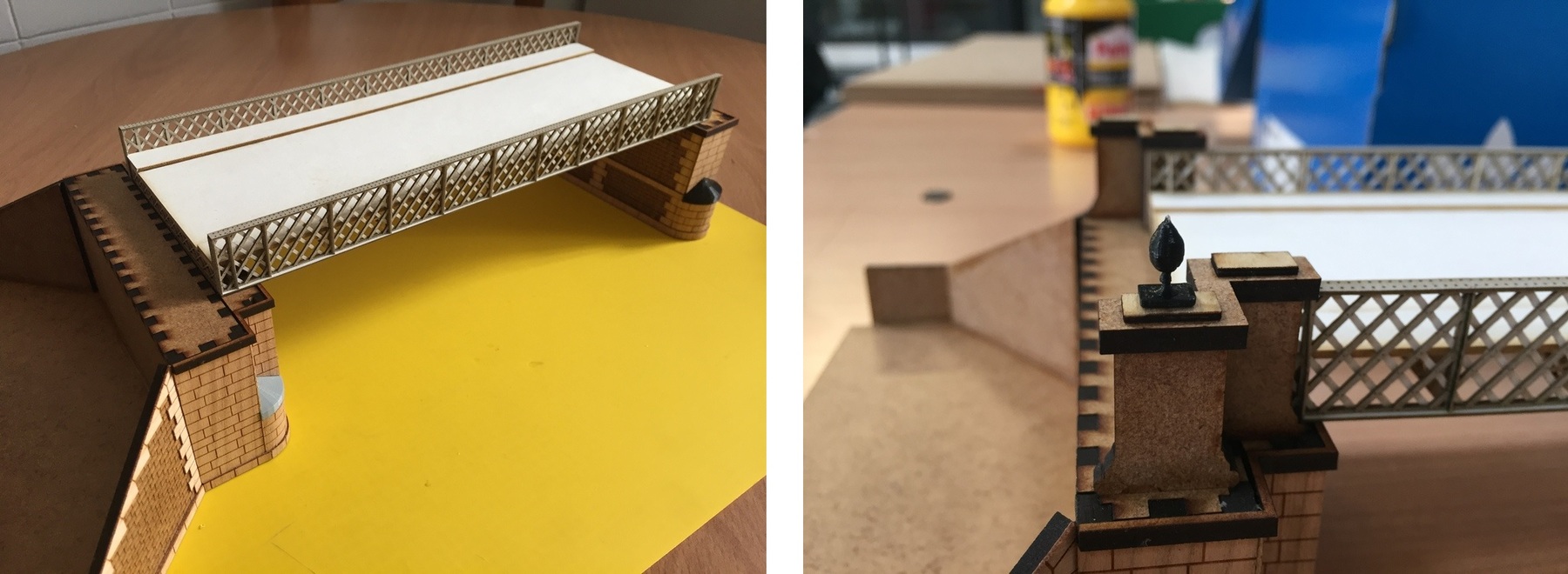
And this is the result, the bridge is made in several pieces so that it can be separated and transported. It is at 1:87 scale.
Files
Find below the files that I made for this assignment.
Review of the class
During the review of this class I volunteered with the acrylic bending with the laser in the minute 1:17:20. 😊