9. Embedded programming
This week’s assignment was to read the datasheet for my microcontroller and use my programmer to program my board to do something.
These were my files for this week.
AtTiny Data Sheet
One of the assignments was to read the AtTiny data sheet. This is where it can be found. 12 While reading the datasheet, I found some pages which I thought were useful to use.
Page 13 of The Data Sheet
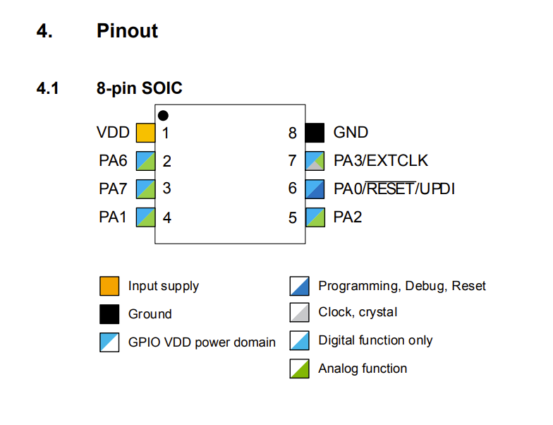
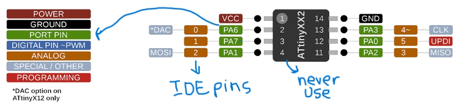
Page 13 is one of the important pages that I found in this data sheet. This page shows the pinouts of the chip. The pinouts of the chip are super important as they help/ guide people to show what the pins mean. These pins can be used to “translate” into different IDEs. For example, I use Arduino IDE. There is a special picture that shows the pinouts of the AtTiny 412 to the Arduino’s pins.
Page 13
AtTiny 412 pinouts for Arduino
Page 105 of the Data Sheet
Page 105 of the data sheet explains the Ports and their functions. It taught me about port pins, individual configuration of input and output pins, inverted I/O, and pullup. Although I did not fully understand what the datasheet meant I tried my best and even used google to understand a quick grasp of what I am reading.
Ports and Pins
A simple explanation of Ports and pins would be that ports are represented by registers inside the microcontroller and allow the program (firmware) to control the state of the pins, or conversely, read the state of the pins if they are configured as inputs.
| Data Sheet Terms & Concepts | Description/ Definition | Websites/ Resources Used |
|---|---|---|
| Ports | Ports are represented by registers inside the microcontroller and allow the program (firmware) to control the state of the pins, or conversely, read the state of the pins if they are configured as inputs. | Website |
| Pins | The pins are what stick out of an IC, and connect electrically to the outside world. | Website |
Conclusion
Reading the datasheet is helpful because it can clear up any confusion as well as prevent many mistakes. It is important to know the limits of your piece of electronic, so you can use it to its full potential. In the future, I definitely plan on looking at and reading that data sheet prior to starting a project.
Use your Programmer to Program your Board to do Something
The next assignment was to use your Programmer to do something, I decided to use a custom milled board which I had completed during Week 7. I had made a blinky board. I had already completed the PCB design in KiCad. This board used an AtTiny 412 chip, an LED, and a button. The function of the board was to turn the LED on/off using the button. By doing this in a previous week, I realized I could also use it for this week.
To revise, here is the code I used:
Code
void setup() {

//start serial connection

Serial.begin(9600);

//configure pin 2 as an input and enable the internal pull-up resistor

pinMode(2, INPUT_PULLUP);

pinMode(4, OUTPUT);

}

void loop() {

//read the pushbutton value into a variable

int sensorVal = digitalRead(2);

//print out the value of the pushbutton

Serial.println(sensorVal);

// Keep in mind the pull-up means the pushbutton's logic is inverted. It goes

// HIGH when it's open, and LOW when it's pressed. Turn on pin 13 when the

//buttons pressed, and off when it's not:

if (sensorVal == HIGH) {

digitalWrite(4, LOW);

} else {

digitalWrite(4, HIGH);

}
}
Here is the video of my Blinky Board working from the previous week:
Video
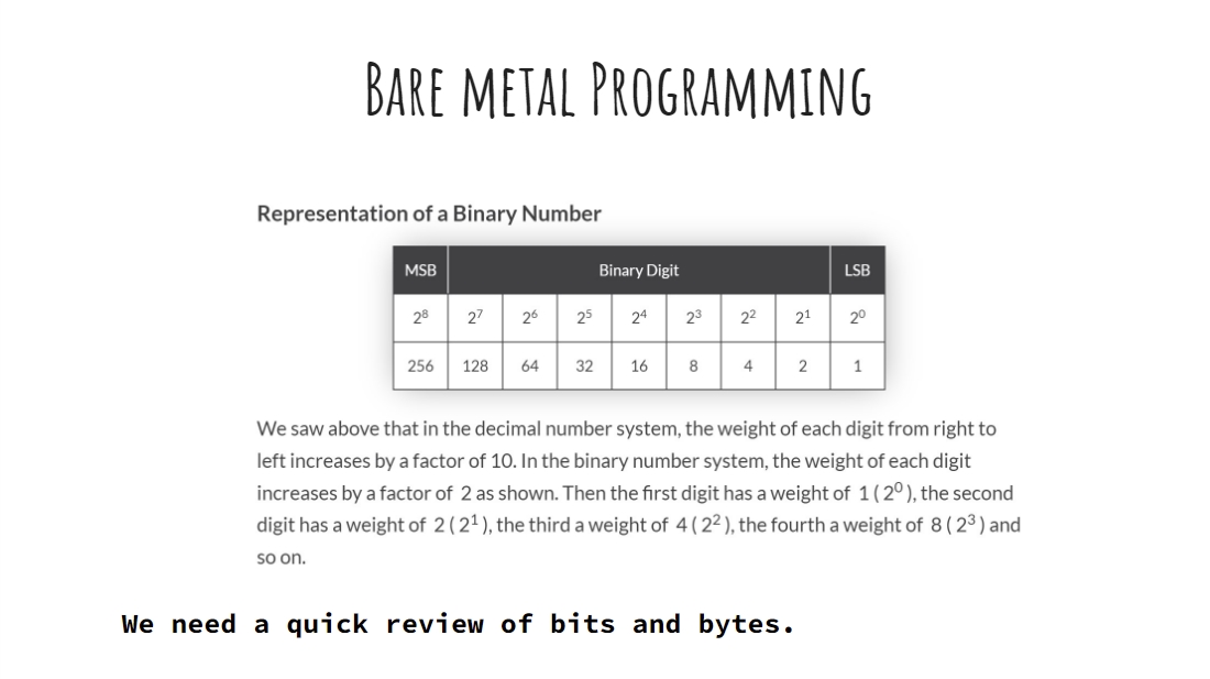
Bare Metal Programming
Since this was done a previous week, I decided that I wanted to dive further into this topic and decided to use Bare Metal Programming to do the same steps as described above.
This is where I would use the datasheet to my advantage, as well as use binary in Arduino IDE to directly communicate with the memory of the chip. This eventually led me to understand how the chip really works.
Since I have never done this before our lab instructor provided the entire lab with a presentation on Bare Metal Programming. Below is the presentation I used to help me learn.
I worked through all of these slides and even made many Tinker Cad circuits. I also learned how to flash an internal LED of an Arduino. This is helpful, so you can check if the Ardunio is working and if your code is working too.
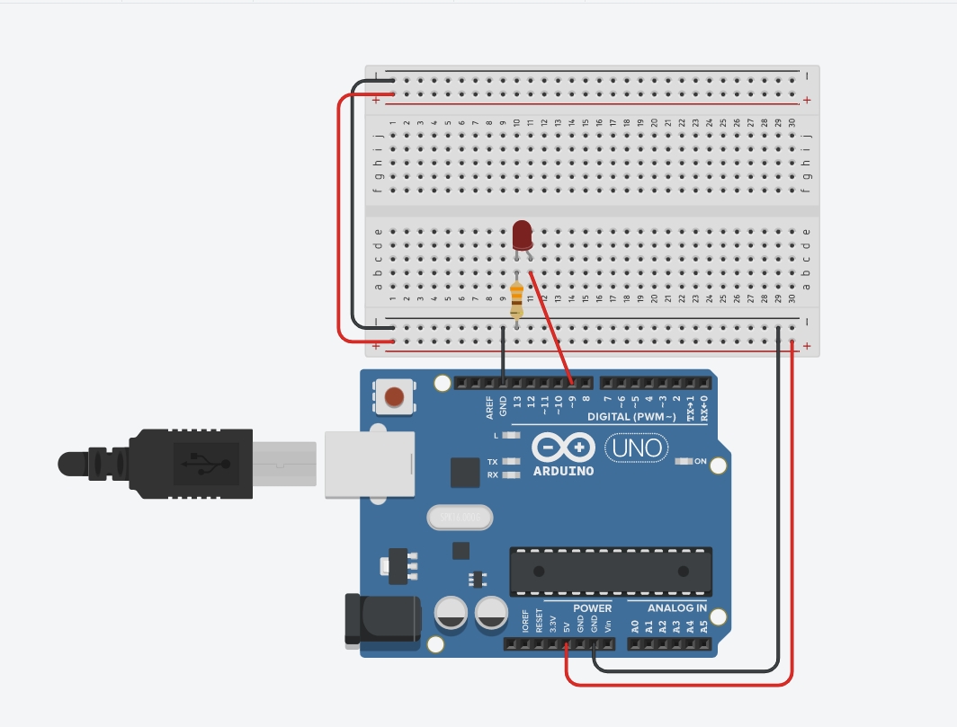
By following the presentation, I made a simple circuit that would flash an LED. Pretty simple right? But here’s the catch, I learned how to do this in 3 different ways.
Here is what the circuit looked like;
TinkerCad Circuit
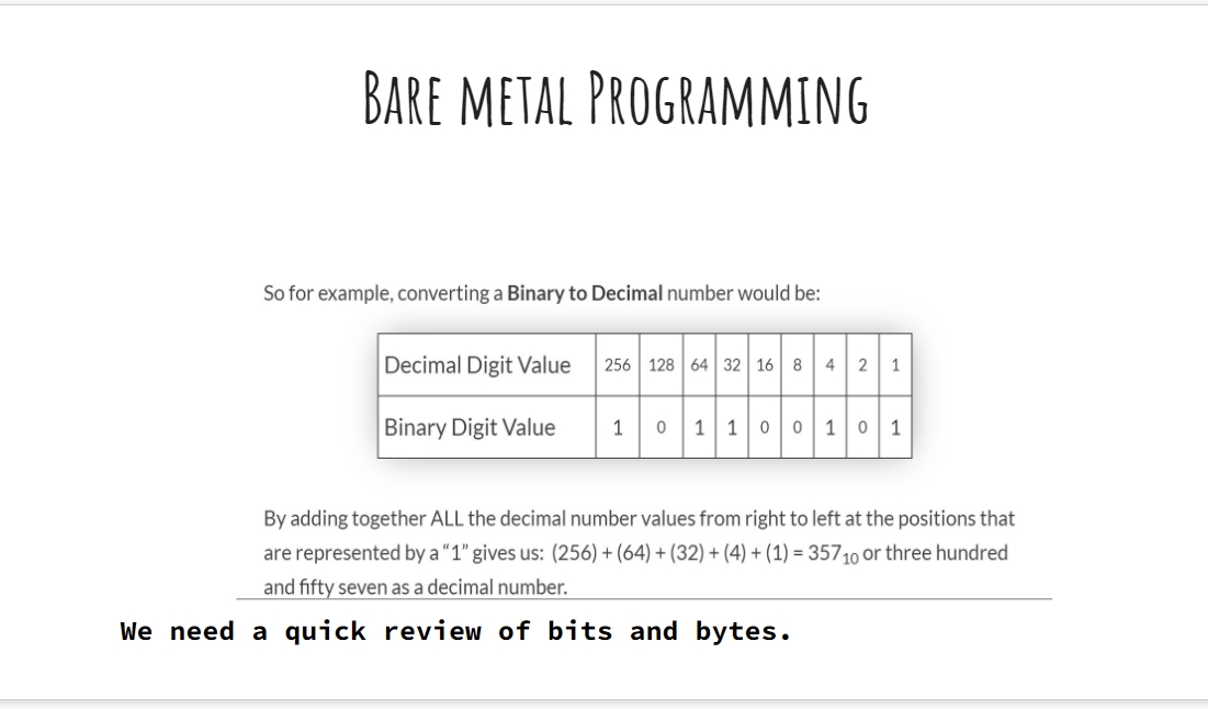
The first way was to do it using Binary to flash the LED.
Since I had taken AP Computer Science this year, my teacher had taught us Binary, so I had some background knowledge on this topic.
For users reading this, refer to the pictures below to understand how to use Binary:
This is the binary code I used:
void setup()
{
pinMode(9, OUTPUT);
}

void loop()
{
PORTB=B00000010;
delay(1000);
PORTB=B00000000;
delay(1000);
}
Tinker Cad Binary Circuit
The second way was by using decimal:
This is the code I used for that:
Tinker Cad Decimal Circuit
The last method was using a DDR Register:
The DDR register, determines whether the pin is an INPUT or OUTPUT.
void setup()
{
//pinMode(9, OUTPUT);
DDRB = 9;
}

void loop()
{
PORTB=2;
delay(1000);
PORTB=0;
delay(1000);
}
Tinker Cad DDR Registor Circuit
Using Custom PCB Blinky Board with Bare Metal
This was now a step up from what I had previously done.
To do this, I followed the same code above but changed my pins according to the ones I had in Week 7
To begin writing the code I used my Kicad schematic from Week 7. I checked this schematic to see which pin my LED was connected to, which would then lead me to which port on the Arduino I had to access.
My LED was on pin 3, which meant that in Arduino IDE it was on pin 1. To find out which port this pin was on I referred to the datasheet of the AtTiny 412, which was linked previously in this documentation. By looking at this documentation, I figured out that my pin resides in Port 1.
Here is the pinout found on Page 13.
Page 13 of Datasheet Pinout
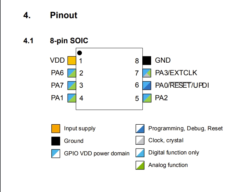
Along with the pinouts the manufacturer has also given a legend/key to explaining what all the colors and annotations mean.
While thinking and constructing this code, I wasn’t sure how to really do it. Coding is not really my forte, although with practice and learning I am going to get better. To help me I followed one of my classmates Nicholas Niles documentation. He mentioned getting help from another Fab student, Alaric Pan. Alaric found out about how to access these ports and resisters through the datasheet as well as, previous Fab Academy students from our lab. All this lead me to thoroughly read page 108 of the datasheet.
Page 108 of Datasheet
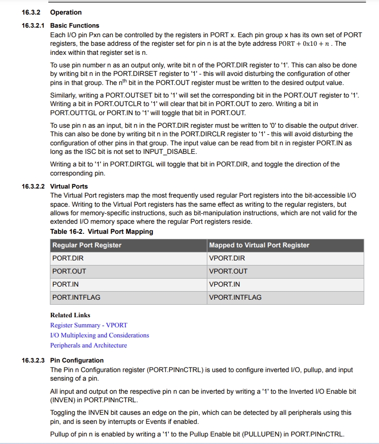
After reading this and referring to both my college’s documentation, I learned that my board’s lead is on PA7.
P standing for the port. Standing for the AtTiny’s port category. 7 is the pin number.
Looking back to page 108, the syntax for my board would be PORTA.
Writing Bare Metal Code
I am not very talented in coding, just because it is all very new to me, and this is my first time hearing about Bare Metal Programming. Although, I am very eager to learn so I can have a varied skill set.
To get a brief outline of what my code would look like, I looked at Nicholas Nile’s documentation. I made the necessary changes that needed to be made to the code, and this is what my final code looked like. Not many changes were needed.
Bare Metal Programming
This first code uses the number 7 instead of making it into a variable. This was the code used by Nick inspired by Alaric.
Bare Metal without Integers
void setup() {
// put your setup code here, to run once:
PORTA.DIRSET |= 1 << 7;
}

void loop() {
// put your main code here, to run repeatedly:
PORTA.OUT |= 1 << 7; //sets to high
delay(100);
PORTA.OUT &= ~(1 << 7); //sets to low
delay(100);
}
Final Results
Bare Metal With Integers
int pinNum = 7; //Number for LED Pin
int delayTime = 1000;

void setup() {
PORTA.DIRSET |= 1 << pinNum;
}

void loop() {
PORTA.OUT |= 1 << pinNum;
delay(delayTime);
PORTA.OUT &= ~(1 << pinNum);
delay(delayTime);
}
Bare Metal wih Integers
These were my files for this week.
Group Work
Aaron, Alaric, Jada, and I worked on using a Jetson NANO to blink an LED. You can see more on that on our groupsite