12. Output devices
This weeks assingment was to add an output device to a microcontroller board you’ve designed, and program it to do something.
For this week, I wanted to make an putput decice which emmited light and something that could be integrated into my final project.
I chose Neopixels, such a simple thing, although they create such beutiful colors and you can do so many things with them.
Here are some cool projects you can do with Neopixels.
These are my files for this week.
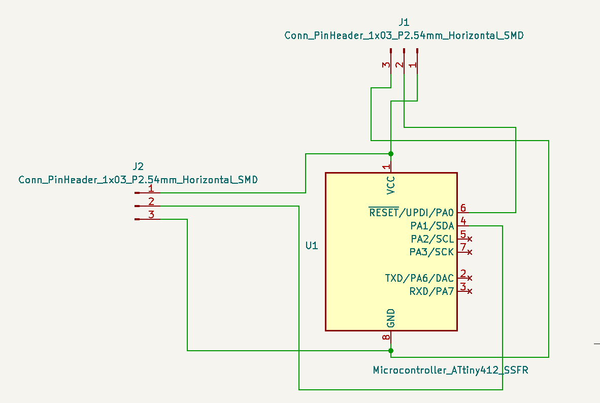
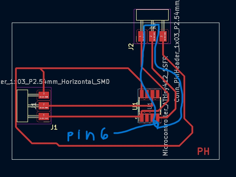
Designing Schematic
This schematic was one to the easiset.
Bill of Materials (BOM):
- AtTiny 412
- 3 pin Headers (x2)
To design my board, I used KiCad, since I have had experience witht this software my desiging process went flawless.
I connected the appropraite pins to the Attiny 412, and the headers, finally finishin my schematic.
Schematic
PCB Design
After making the schematic, I made a PCB version of it. While esiting my traces, I relaized that I needed to make the trace width thicker. I changes the trace width to 0.4. This is so when the board is milled, the traces are not too thin.
Thin traces, usally lead to ripped traces.
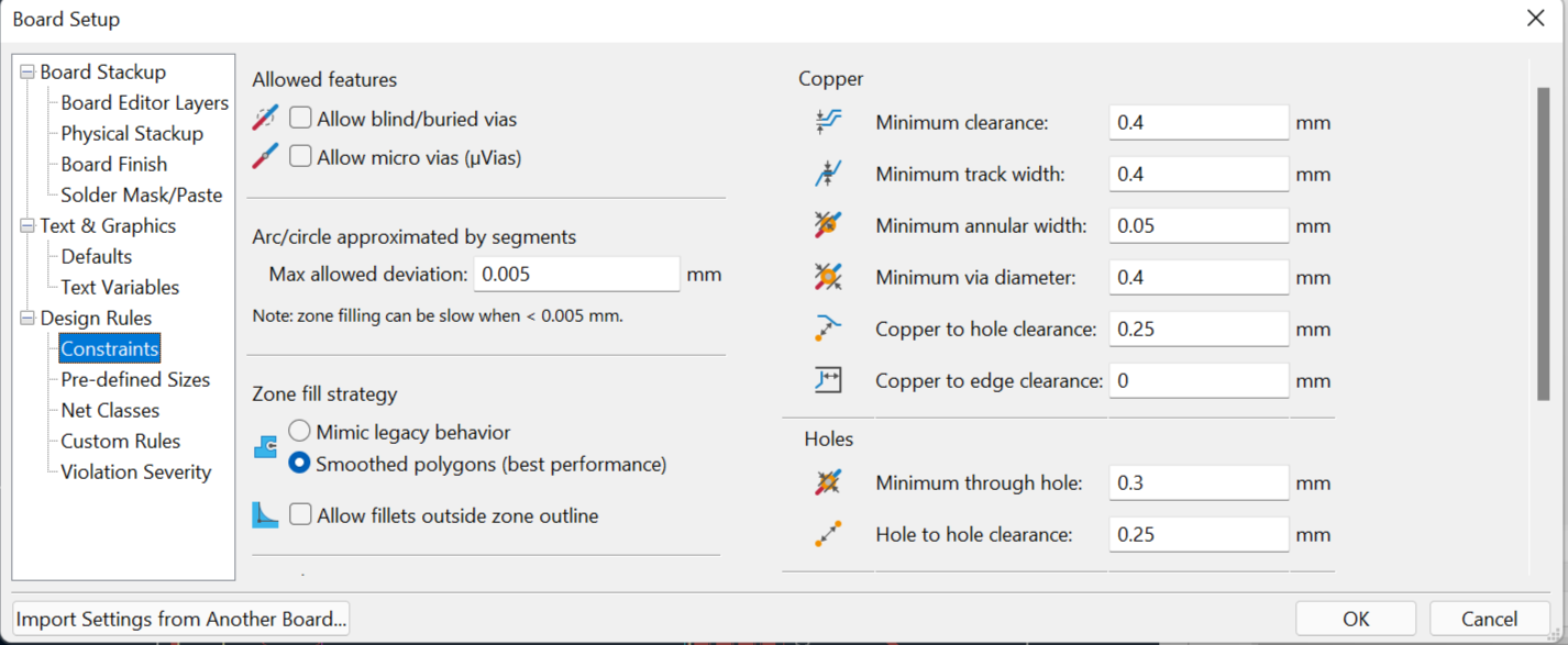
How to change the trace width?
To change the trace width, go to:
File —> Board Setup —> Constraints
In the constraints section, change the minimum clearance and track width to 0.4 mm
Once changing the trace width, I drew all the traces to the appriapratiate components. In this process, I also learned how to use a 0 ohm resistor.
What is a 0 ohm resistor used for?
A 0 ohm resistor can be used to jump over traces if it is hard to connect a trace togther. Another reason they are used is because there they are easy to assemble and are cheap.
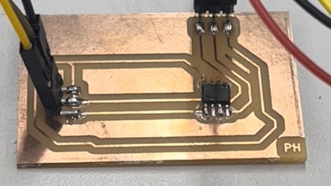
Final PCB

Milling out the PCB
Once the PCB was designed, I decided to mill out my board. This was a sinple and one step process as I have done it many times and now am familar with the process. To see a more in deoth explination of my process, check my previous pages.
** Milling in Progress**
** Final Board**
Uploading to Neopixels from Ardunio
Once your board is milled out and you know for a fact that your neopixels string works (hint: test just the neopixels with the ardunio).
How to Test Just Neopixels and Ardunio
You should connect pins onto the correct pads of the strip. DO NOT USE MALE TO FEMALE WIRES. Use solid copper wires instead.
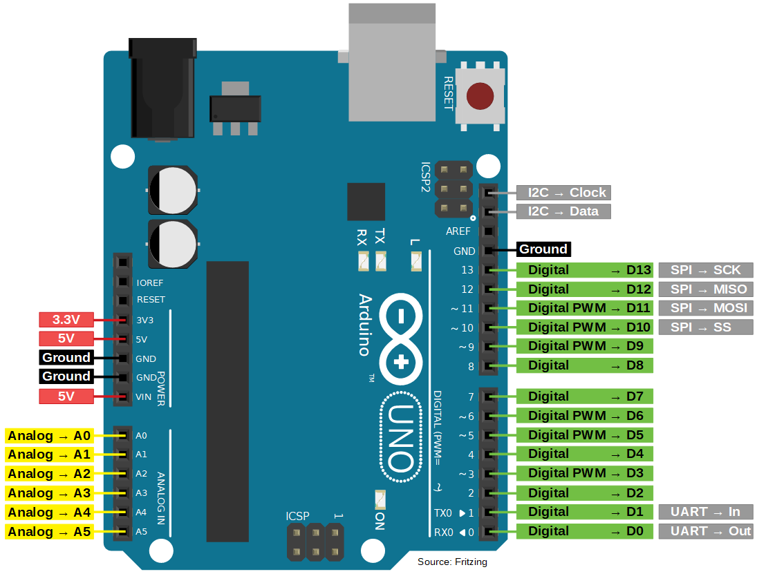
Connect ground, power (vcc), and the data pin into the arduinio.
DISTINCTION!!! Data pin on neopixels themselfs are NOT the UPDI.
Arduino itslef has ITS OWN UPDI which is pin 6. How do I know that? Well the answer is the pin out sheet for Ardunio and some resaerch.
Arduino (328P): PD6 -> Digital Pin 6
Once connecting all pins, it is time to actually use the data pin of the neopixels to upload some code and see if the neopixels work. I went on the Ardunio IDE, and chose a code from the examples section. I chose a simple code, so I could first understnd the basic concept of how Neopixels work.
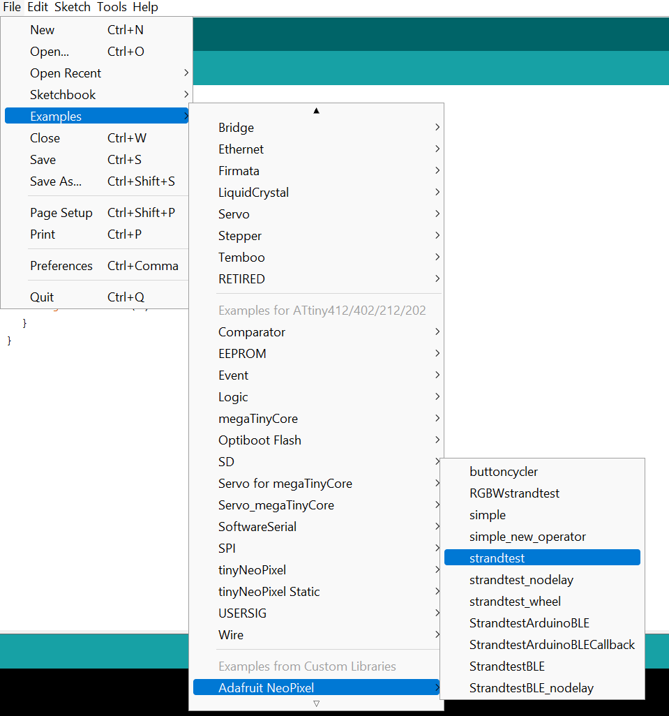
These were the settings of my Ardunio connected to the neopixels. These would help import the code written.
Once checking all this is in place, copy/paste this code below:
#ifdef __AVR__
 #include <avr/power.h> // Required for 16 MHz Adafruit Trinket
#endif

// Which pin on the Arduino is connected to the NeoPixels?
// On a Trinket or Gemma we suggest changing this to 1:
#define LED_PIN    5

// How many NeoPixels are attached to the Arduino?
#define LED_COUNT 3

// Declare our NeoPixel strip object:
Adafruit_NeoPixel strip(LED_COUNT, LED_PIN, NEO_GRB + NEO_KHZ800);
// Argument 1 = Number of pixels in NeoPixel strip
// Argument 2 = Arduino pin number (most are valid)
// Argument 3 = Pixel type flags, add together as needed:
//   NEO_KHZ800  800 KHz bitstream (most NeoPixel products w/WS2812 LEDs)
//   NEO_KHZ400  400 KHz (classic 'v1' (not v2) FLORA pixels, WS2811 drivers)
//   NEO_GRB     Pixels are wired for GRB bitstream (most NeoPixel products)
//   NEO_RGB     Pixels are wired for RGB bitstream (v1 FLORA pixels, not v2)
//   NEO_RGBW    Pixels are wired for RGBW bitstream (NeoPixel RGBW products)


// setup() function -- runs once at startup --------------------------------

void setup() {
  // These lines are specifically to support the Adafruit Trinket 5V 16 MHz.
  // Any other board, you can remove this part (but no harm leaving it):
#if defined(__AVR_ATtiny85__) && (F_CPU == 16000000)
  clock_prescale_set(clock_div_1);
#endif
  // END of Trinket-specific code.

  strip.begin();           // INITIALIZE NeoPixel strip object (REQUIRED)
  strip.show();            // Turn OFF all pixels ASAP
  strip.setBrightness(50); // Set BRIGHTNESS to about 1/5 (max = 255)
}


// loop() function -- runs repeatedly as long as board is on ---------------

void loop() {
  // Fill along the length of the strip in various colors...
  colorWipe(strip.Color(255,   0,   0), 50); // Red
  colorWipe(strip.Color(  0, 255,   0), 50); // Green
  colorWipe(strip.Color(  0,   0, 255), 50); // Blue

  // Do a theater marquee effect in various colors...
  theaterChase(strip.Color(127, 127, 127), 50); // White, half brightness
  theaterChase(strip.Color(127,   0,   0), 50); // Red, half brightness
  theaterChase(strip.Color(  0,   0, 127), 50); // Blue, half brightness

  rainbow(10);             // Flowing rainbow cycle along the whole strip
  theaterChaseRainbow(50); // Rainbow-enhanced theaterChase variant
}


// Some functions of our own for creating animated effects -----------------

// Fill strip pixels one after another with a color. Strip is NOT cleared
// first; anything there will be covered pixel by pixel. Pass in color
// (as a single 'packed' 32-bit value, which you can get by calling
// strip.Color(red, green, blue) as shown in the loop() function above),
// and a delay time (in milliseconds) between pixels.
void colorWipe(uint32_t color, int wait) {
  for(int i=0; i<strip.numPixels(); i++) { // For each pixel in strip...
    strip.setPixelColor(i, color);         //  Set pixel's color (in RAM)
    strip.show();                          //  Update strip to match
    delay(wait);                           //  Pause for a moment
  }
}

// Theater-marquee-style chasing lights. Pass in a color (32-bit value,
// a la strip.Color(r,g,b) as mentioned above), and a delay time (in ms)
// between frames.
void theaterChase(uint32_t color, int wait) {
  for(int a=0; a<10; a++) {  // Repeat 10 times...
    for(int b=0; b<3; b++) { //  'b' counts from 0 to 2...
      strip.clear();         //   Set all pixels in RAM to 0 (off)
      // 'c' counts up from 'b' to end of strip in steps of 3...
      for(int c=b; c<strip.numPixels(); c += 3) {
        strip.setPixelColor(c, color); // Set pixel 'c' to value 'color'
      }
      strip.show(); // Update strip with new contents
      delay(wait);  // Pause for a moment
    }
  }
}

// Rainbow cycle along whole strip. Pass delay time (in ms) between frames.
void rainbow(int wait) {
  // Hue of first pixel runs 5 complete loops through the color wheel.
  // Color wheel has a range of 65536 but it's OK if we roll over, so
  // just count from 0 to 5*65536. Adding 256 to firstPixelHue each time
  // means we'll make 5*65536/256 = 1280 passes through this loop:
  for(long firstPixelHue = 0; firstPixelHue < 5*65536; firstPixelHue += 256) {
    // strip.rainbow() can take a single argument (first pixel hue) or
    // optionally a few extras: number of rainbow repetitions (default 1),
    // saturation and value (brightness) (both 0-255, similar to the
    // ColorHSV() function, default 255), and a true/false flag for whether
    // to apply gamma correction to provide 'truer' colors (default true).
    strip.rainbow(firstPixelHue);
    // Above line is equivalent to:
    // strip.rainbow(firstPixelHue, 1, 255, 255, true);
    strip.show(); // Update strip with new contents
    delay(wait);  // Pause for a moment
  }
}

// Rainbow-enhanced theater marquee. Pass delay time (in ms) between frames.
void theaterChaseRainbow(int wait) {
  int firstPixelHue = 0;     // First pixel starts at red (hue 0)
  for(int a=0; a<30; a++) {  // Repeat 30 times...
    for(int b=0; b<3; b++) { //  'b' counts from 0 to 2...
      strip.clear();         //   Set all pixels in RAM to 0 (off)
      // 'c' counts up from 'b' to end of strip in increments of 3...
      for(int c=b; c<strip.numPixels(); c += 3) {
        // hue of pixel 'c' is offset by an amount to make one full
        // revolution of the color wheel (range 65536) along the length
        // of the strip (strip.numPixels() steps):
        int      hue   = firstPixelHue + c * 65536L / strip.numPixels();
        uint32_t color = strip.gamma32(strip.ColorHSV(hue)); // hue -> RGB
        strip.setPixelColor(c, color); // Set pixel 'c' to value 'color'
      }
      strip.show();                // Update strip with new contents
      delay(wait);                 // Pause for a moment
      firstPixelHue += 65536 / 90; // One cycle of color wheel over 90 frames
    }
  }
}
So to summmarize what pins were connected to what:
Neopixel Ground —> Arduino Ground
Neopixel Power (VCC) —> Arduino Power (VCC)
Neopixel Data Pin —> Any pin on Arduino (pin 5)
UPDI I slaready buildt into the Ardunio, so pin 6 is NOT connnected to anything but the IDE will upload the code through that, but your pins will be the ones above.
Once all is connected and you have made sure all the board settings are correct, upload the program and voila!
Using Custom Milled Board and Arduino
Once testing the Neopixel from just the Arduino, it is time to use the milled board that you made. The purpose of the neopixels just with the Arduino was to test if the strand actually worked. Now that we know the strand actually works, we can test it with our board.
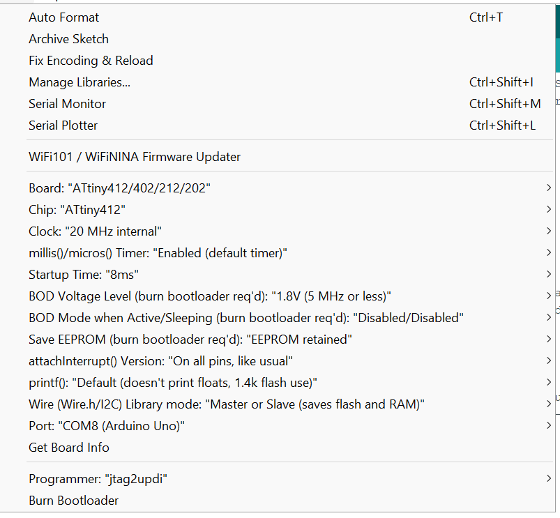
I followed my schmatic which was pretty easy to follow as there were very little components. After wiring up the correct wires to each pther and double checking, I uploaded a different code than above. This code can be found in the examples, and is called simple. This time, I chnaged the board settings to somethign slightly different.
These were the board settings:

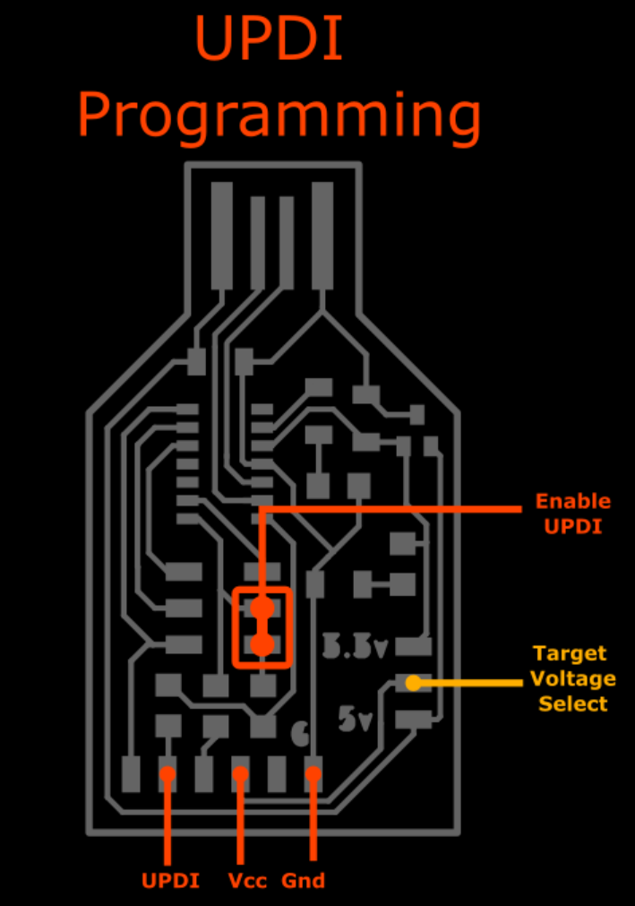
DONT forget to make your Ardunio into a programmer. JTAGUPDI!!!
After checking all the wiring is right, I uploaded the code below and my board finally worked!! This assured me that my board is working and the final step would be to upload this program using my SAMD-11 Microcontroller.
Although before doing that, dowlond this library for the Neopixels to br programmed thorugh the AtTiny 412 chips.
Click here Which will take you to the website where you can just click a buttin and you will find a section where you can download the correct Adafruit neopixel library.
// NeoPixel simple sketch (c) 2013 Shae Erisson, adapted to tinyNeoPixel library by Spence Konde 2019.
// released under the GPLv3 license to match the rest of the AdaFruit NeoPixel library

#include <tinyNeoPixel_Static.h>


// Which pin on the Arduino is connected to the NeoPixels?
#define PIN            2

// How many NeoPixels are attached to the Arduino?
#define NUMPIXELS      3

// Since this is for the static version of the library, we need to supply the pixel array
// This saves space by eliminating use of malloc() and free(), and makes the RAM used for
// the frame buffer show up when the sketch is compiled.

byte pixels[NUMPIXELS * 3];

// When we setup the NeoPixel library, we tell it how many pixels, and which pin to use to send signals.
// Note that for older NeoPixel strips you might need to change the third parameter--see the strandtest
// example for more information on possible values.

tinyNeoPixel leds = tinyNeoPixel(NUMPIXELS, PIN, NEO_GRB, pixels);

int delayval = 500; // delay for half a second

void setup() {
  pinMode(PIN, OUTPUT);
  // with tinyNeoPixel_Static, you need to set pinMode yourself. This means you can eliminate pinMode()
  // and replace with direct port writes to save a couple hundred bytes in sketch size (note that this
  // savings is only present when you eliminate *all* references to pinMode).
  // leds.begin() not needed on tinyNeoPixel
}

void loop() {

  // For a set of NeoPixels the first NeoPixel is 0, second is 1, all the way up to the count of pixels minus one.

  for (int i = 0; i < NUMPIXELS; i++) {

    // pixels.Color takes RGB values, from 0,0,0 up to 255,255,255
    leds.setPixelColor(i, leds.Color(0, 150, 0)); // Moderately bright green color.

    leds.show(); // This sends the updated pixel color to the hardware.

    delay(delayval); // Delay for a period of time (in milliseconds).
  }
  // with tinyNeoPixel_Static, since we have the pixel array, we can also directly manipulate it - this sacrifices the correction for the pixel order, and the clarity of setColor to save a tiny amount of flash and time.
  for (int i = 0; i < (NUMPIXELS * 3); i++) {
    pixels[i] = 150; // set byte i of array (this is channel (i%3) of led (i/3) (respectively, i%4 and i/4 for RGBW leds)
    leds.show(); // show
    delay(delayval); // delay for a period of time
    pixels[i] = 0; // turn off the above pixel
    // result is that each pixel will cycle through each of the primary colors (green, red, blue for most LEDs) in turn, and only one LED will be on at a time.
  }
}
Final Result of Custom Board Programming Neopixels Using an Arduino.
Using a MicroController to Program Neopixels
After testing all my boards and strand of neopixel works, I finally decided to program them with my microcontroller. To set myself up for success I reffered to the pinput of the AtTiny 412 and the SAMD-11.
I wired up the microcontroer reffering to this pin out. I also used Dr. Harris’s Website to help me through this process.
After pluging in all the wires corectly, I made sure there were no errors in my code and my set up.
This was my board setup menu:
Next, I checked my code. I used the same example as above, and didnt change the pin numbers in the IDE.
When using the programmer, you have to reffer to the AtTiny 412 pinout chart. This chart saves you from a lot of work.
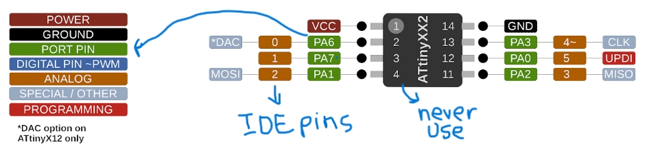
You will NEVER find yourself using the actual numbers of the AtTiny 412 chip, instead when designing your schematics you should look at the pinout and think like your working eith an Arduino. When sleecting what number of pin your board is connected to refer back to your schematic take those AtTiny 412 numbers and translate them to Ardunio.
For example, the code asks what pun is the ARDUNIO connect to on the Neopixels.
1 . refer back to your schematic, see which pin is connected to the neopixels. 2 . Identify the oun in AtTiny 412 numbers. In this case it would be pin 4
3 . Then refer to the 412 pinout sheet, and travlate the pin into Arduino context
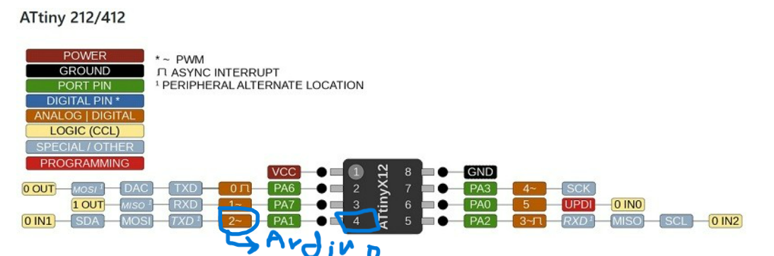
After following ALL these steps, upload your code and voila!!
Final Output Week Assignment
Summary
This week, I learned how to successfully program neo pixels using a microcontroller. This week I realized that my assignment was not too hard, and it was also something that I can use for my final project. All I would need to do is mill a smaller board and attach a longer strip of neo pixels. This week was also one of my awaking weeks. An awaking week is when I finally realized and understand something that I have not quite grasped yet. This week I learned ALL about uploading code from Arduino IDE and the different PINs on an AtTiny 412. I also learn how important pinout charts were. This week what I learn the most was basic how to read PINs and how to write code that calls/correlates to those pins. After my instructor Mr. Dubick sat down with me and explained how these pinouts work, my whole world became a little easier. This concept may seem easy, but this week I understood the why? and how? behind pinouts, schamtics, chip numbers and Ardunio IDE.
These are my files for this week.
Group Work
This weeks groups was to measure the power consumption of an output device. I worked with Aaron Logan to test a DC Motor. This week’s gruowas easy, so Aaro and I split up the work equally. I worked on setting up the motor checking the data sheet for the amount of voltage.
This is our group site. Go check out our process for the group work this week!