11. Input devices
Input week was one of the most interesting/challenging weeks. I learned many things, and also could use this knowledge for my final project. The reason this week was challenging was 2 things.
1 . I chose a new sensor as Dr. Gershenfield had recommended. Due to this, there was very little documentation on how to use the sensor.
2 . I wanted to include lots of jazz and my input. Little did I know, that would require lots of Networking and Communicating, which is a week we have not gotten to yet.
I decided to skip ahead to some weeks to understand what would be needed although during this week I had many tests, so I decided to do something a little more simple.
Here are the filesfor this week
Weeks Assignment
This week’s assignment was to create an input device to add to a microcontroller board and read it. I wanted to create something that contributed to my final project. I decided to create a motion sensor that would control the neo pixels on the edge of my mirror. I initially had this idea during the beginning stages of planning my final project and decided to follow through during this week.
Research
After watching Dr. Gershenfield’s lecture on input devices, I decided to use a doppler radar. Dr. Gernshenfield recommended that we don’t use PIR Sensors because they are outdated and an RCWL0516 Doppler Radar is a newer piece of technology. I originally was going to use a PIR Sensor because there were many resources on the internet to use it. Although the doppler radar is a newer piece of technology, there were not a lot of resources online. This made the assignment a little harder, although this isn’t something I cant handle!
Now that I chose my input device, I wondered if I could add something extra. Looking back at my draft plans, I decided on adding Neopixels, so that they turn on when motion is sensed.
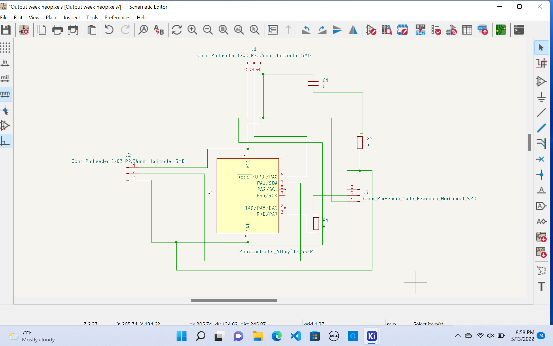
Designing the Schematic
I realized that this board would be similar to the one I had created during Output week. I used the same schematic of the Output board of the neo pixels and simply added an extra 3-pin header. This header was for the doppler radar sensor. I connected the appropriate pins to the AtTiny 412 chip and decided to mill my board.
BOM of Materials
- ATtiny 412 chip
- 3 pin Headers (x3)
- Capacitor (1uf)
- 0 ohm resistors (Used to jump traces)
- Doppler Radar
- Neopixels
- Jumper wires
I designed my board in KiCad, which is the software I have used in the past weeks. I connected all the pins to the headers and chips. I made sure all my taces lead to the correct pin and was ready to design the PCB aspect of my board.
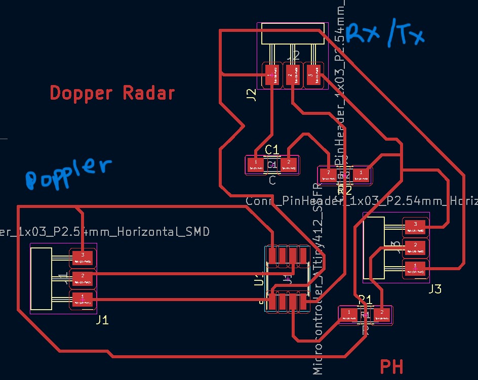
Schmatic Design
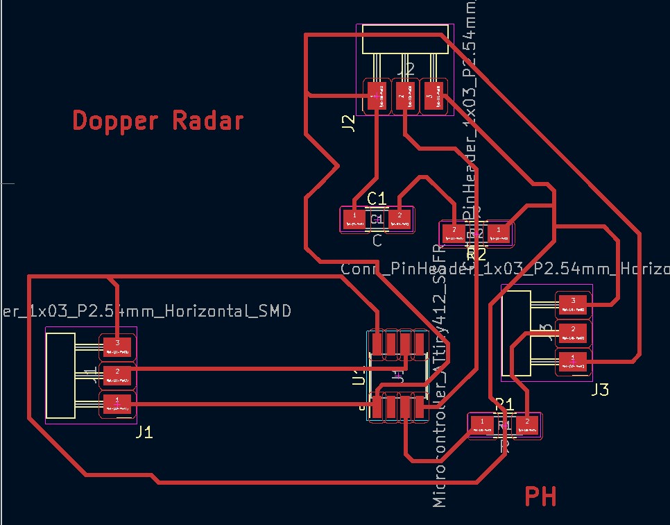
Now, it’s time to design the PCB board, which I am going to mill. Here is my PCB Board.
PCB Design
I plotted my files and milled them.
Milling
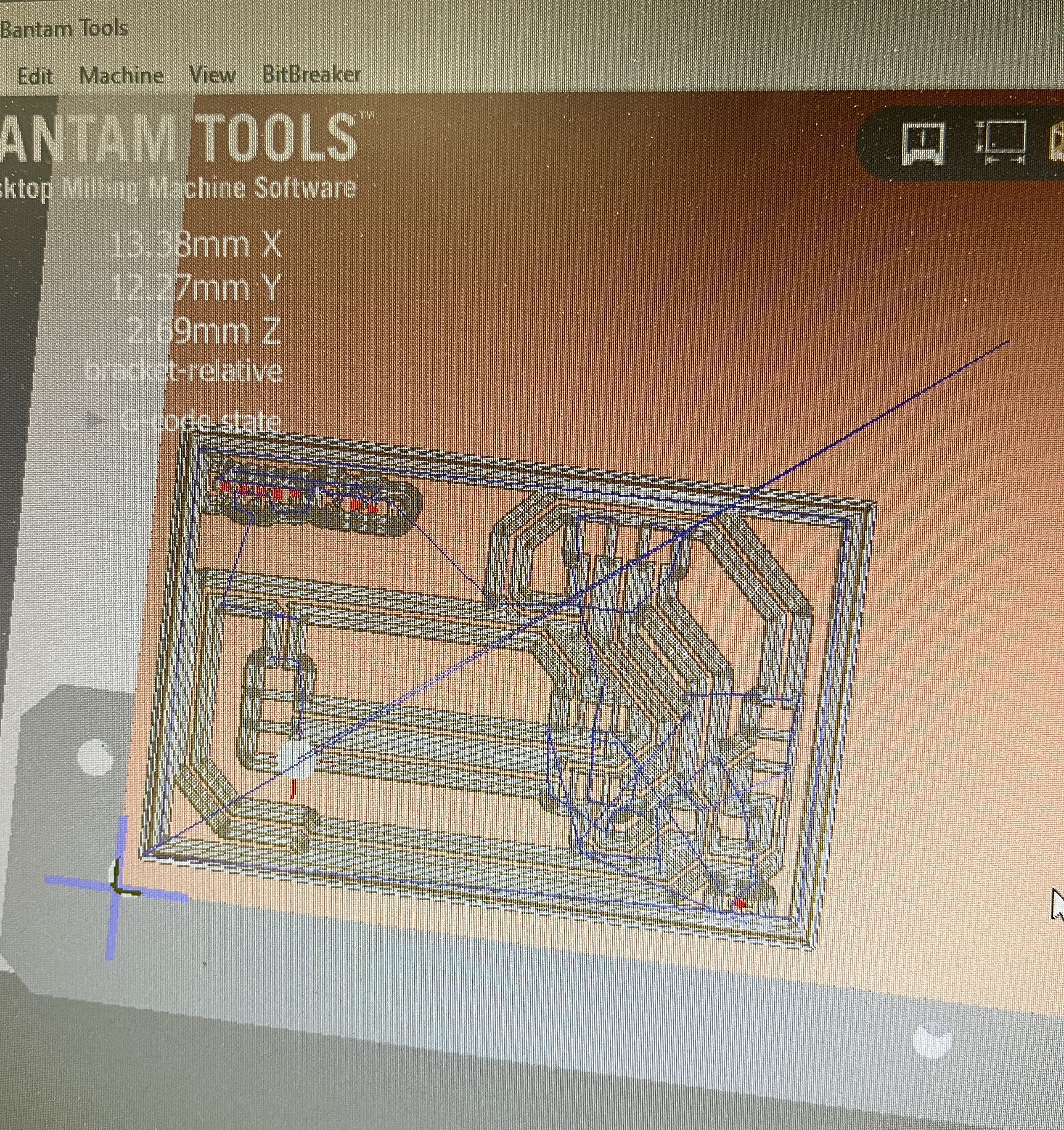
Milling
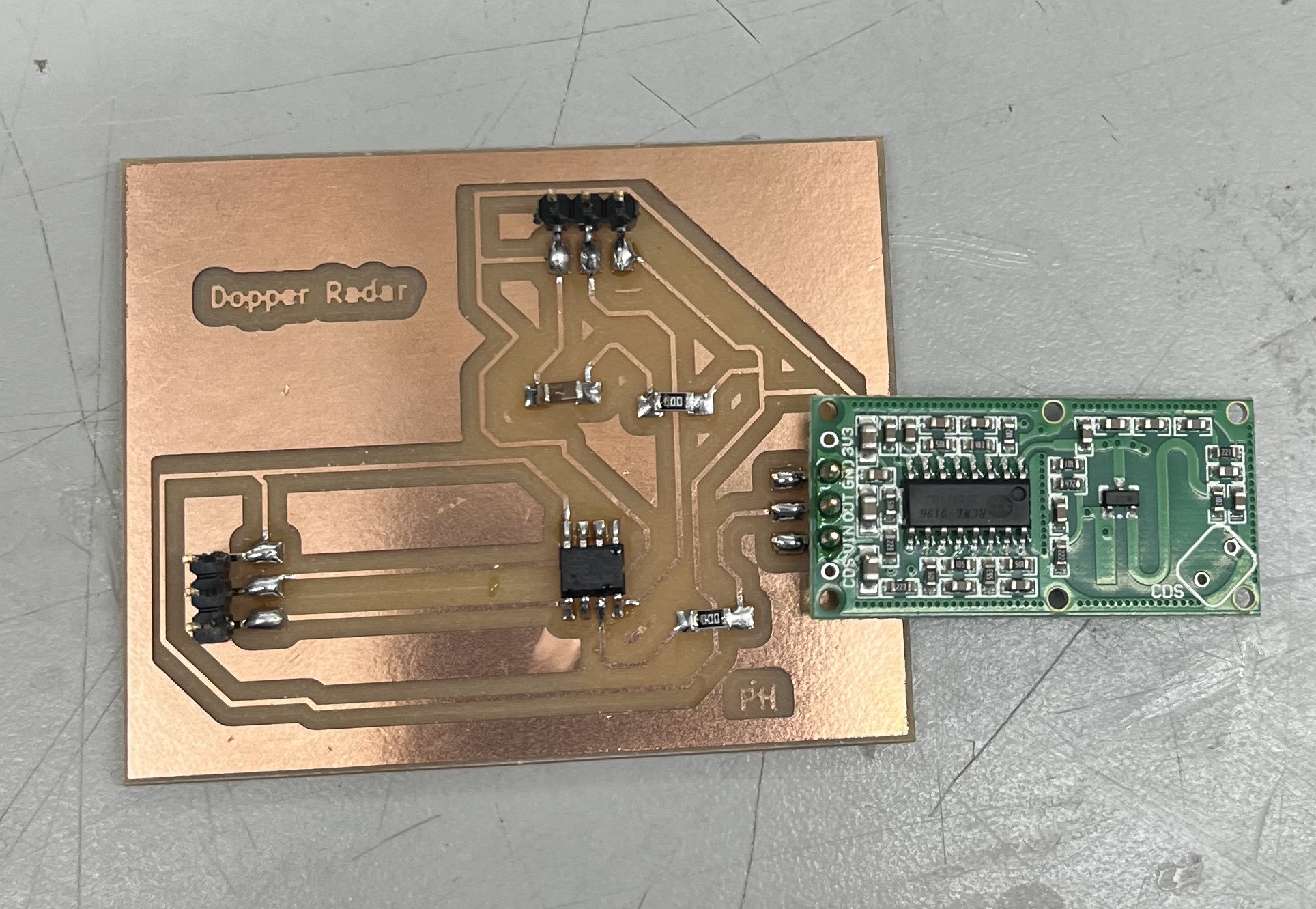
Once, it’s done milling I soldered all the components on.
Time to Program
I read the data sheet of the sensor to see how to use it, and in the datasheet was provided a test code to print to the serial monitor whether there was motion detected or not.
int detectPin = 10;
bool detect = false;
int led = 13;
void setup() {
 Serial.begin(115200);
 Serial.println("Starting...\n");
 pinMode (detectPin, INPUT);
 pinMode (led, OUTPUT);
}
void loop() {

 detect = digitalRead(detectPin);
 if(detect == true) {
 digitalWrite(led, HIGH);
 Serial.println("Movement detected");
 }
 else {
 digitalWrite(led, LOW);
 }
 delay(1000);
}
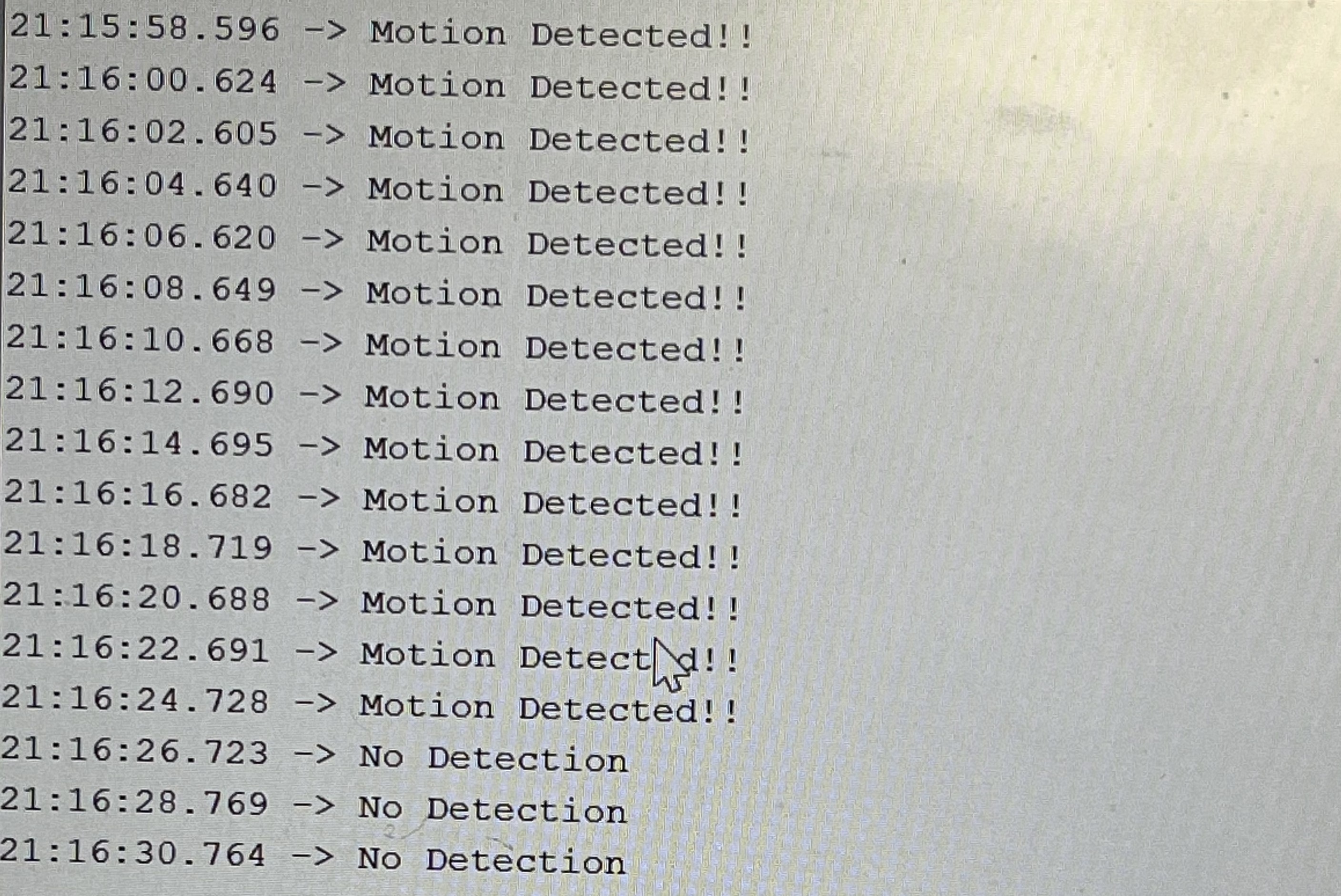
I used this code, and these are the results I got. This was just to check whether or not the sensor is working. The sensor although would only print “Motion Detection”, and would never print “Any Motion”.
It would look something like this:
Video Of Test
To fix that, I decided to research, and found a video that explained it perfectly!
I decided to test out what he was talking about, and tested his code as well as made some modifications to it.
#define Sensor 2

void setup(){
  pinMode (Sensor,INPUT);
  Serial.begin(9600);
}

void loop(){

bool Detection= digitalRead(Sensor);

if (Detection==HIGH)
Serial.println("Motion Detected!!");

else
if (Detection==LOW)
Serial.println("No Detection");
delay(2000);
}
Video Of it Working
Testing Doppler & LED
Next, I tested the Doppler Radar with an LED. Doing this with one LED Is easier than a whole strip of Neopixels because it’s harder to program neo pixels, as they require specific libraries, whereas LEDs are simple and easy.
Wiring
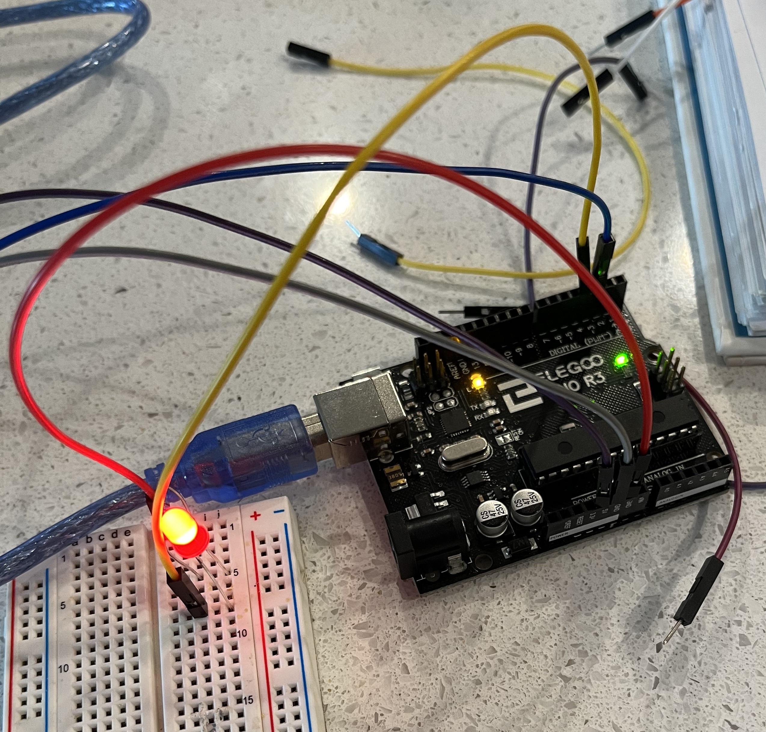
Here was my code:
#define Sensor 2
#define LED 3

void setup(){

  pinMode (Sensor,INPUT);
  pinMode (LED, OUTPUT);
}

void loop (){
bool Detection = digitalRead(Sensor);

if (Detection ==HIGH)
digitalWrite(LED,HIGH);
if (Detection==LOW)
digitalWrite(LED,LOW);
}
Video Of it Working
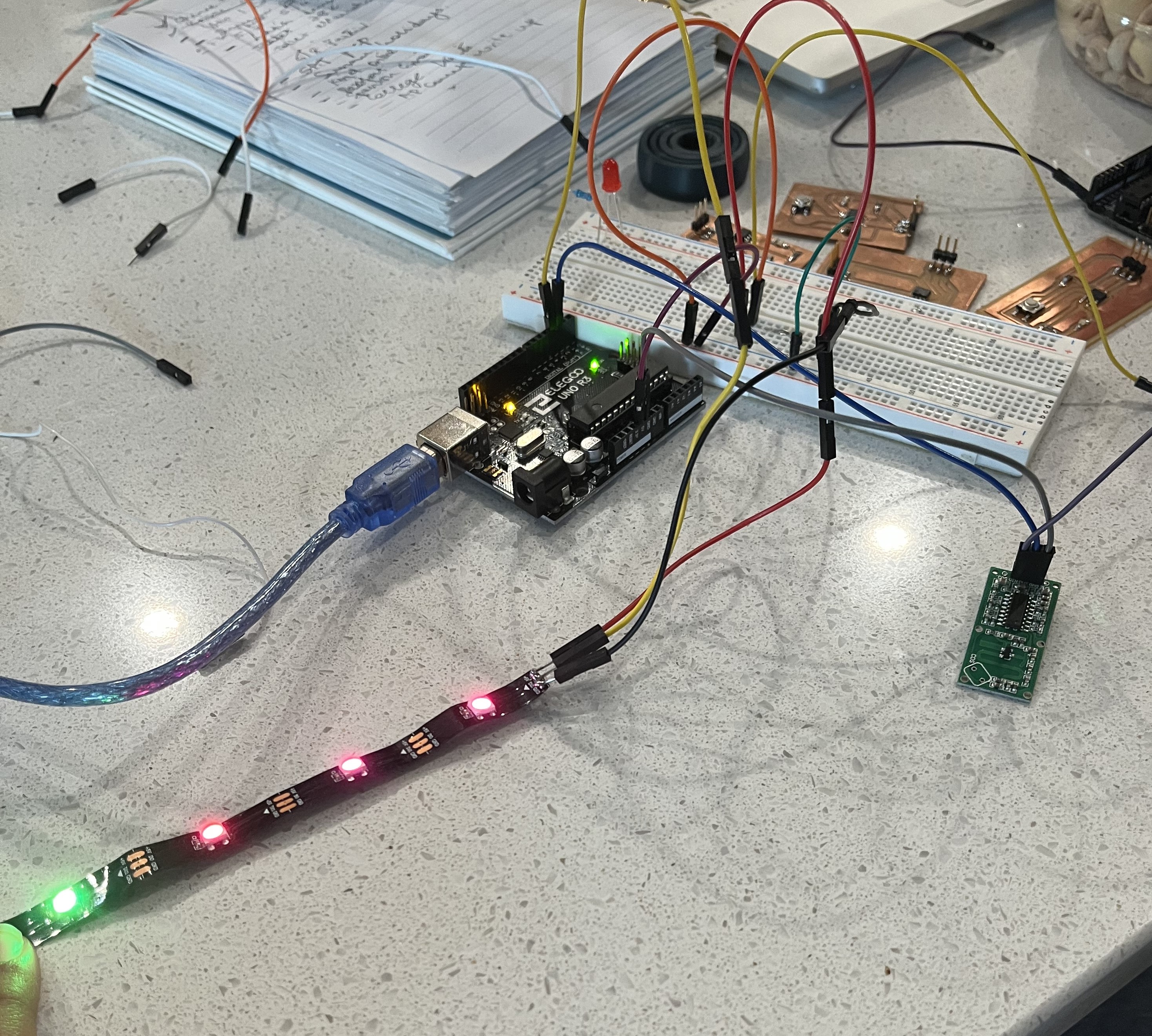
Testing with Neopixels, Doppler Radar, & Ardunio
Once I knew the doppler was working, I decided to connect the doppler radar and neo pixels to a breadboard and program them with an Arduino.
I connected all the correct pins into the Ardunio, such as GRND, VCC, and Data line. I also connected the Doppler radar the same way.
Wiring
Here’s my code:
#include "FastLED.h"
//#include <tinyNeoPixel_Static.h>
#define LED_DATA_PIN 3
#define Sensor 1
#define NUM_LEDS 3
CRGB leds[NUM_LEDS];

int onTime = 5*1000; // 30 seconds
int motion_sensor = 1;


void setup() {
  FastLED.addLeds<WS2811, LED_DATA_PIN, BRG>(leds, NUM_LEDS);

  pinMode (Sensor,INPUT);
  Serial.begin(9600);
}

void loop() {

bool Detection= digitalRead(Sensor);

if (Detection==1){
Serial.println("Motion Detected!!");

/*
leds[0] = CRGB::Red; //glow 1st led as green
leds[1] = CRGB::Green; //glow 1st led as green
leds[2] = CRGB::Green; //glow 1st led as green
leds[3] = CRGB::Green; //glow 1st led as green
*/
FastLED.show(); // apply the function on led strip
delay(5000);
}

else if (Detection==0){
Serial.println("No Detection");

leds[1] = CRGB::Blue; //glow 1st led as blue

FastLED.show(); // apply the function on led strip

delay(5000);
}

}
Everything working together
After hours of studying the PCB Design, and talking to Dr. Harris, he figured out that I had my RX/TX pin on the alternate pins of my 412 chip. This meant that I needed one line of code which would tell the chip, that I am using the alternate RX/TX pin.
This tells the AtTiny 412 chip to use those pins as its RX/TX pin.The reason I have an RX/TX pin is that I needed to use an FTDI (UART chip made by FTDI) board to view the accurate values coming in from the doppler on my serial port.
Here is the pin out from the ATTiny 412:
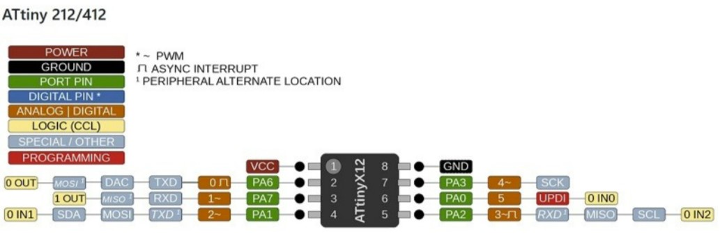
As you can see, pin 4 and pin 5 all have RX and TX, although there is one. The line of code above ensures that the 412 chip knows the traces are going to these pins.
This is a VERY VERY VERY important step, if you do not do it your board won’t work.
Overview of how everything will function
So for this week, I decided last moment to not do the neo pixels and save them for later, because I was already behind on some of my weeks and needed to catch up on those.
Here are the steps which I executed for my assignment to do successfully and smoothly:
1 . First, I uploaded code to my AtTiny 412 chip
Code
#define Sensor 5

void setup(){
pinMode (Sensor,INPUT);
Serial.swap(1);
Serial.begin(9600);
}

void loop(){

bool Detection= digitalRead(Sensor);

if (Detection==HIGH)
Serial.println("Motion Detected!!");

else
Serial.println("No Detection");
delay(6000);
}
For doing this, I used an Arduino and uploaded the code to the chip.
2 . After uploading the code, I plugged in the Doppler Radar, with the pins GRND, VCC, and Data pin.
I also plugged in the God, VCC, and RX lines to the FTDI (UART chip made by FTDI).
A more depth video explanation is linked at the end of these step-by-step instructions.
3 . I connected the FTDI (UART chip made by FTDI), to my computer and chose the appropriate port, and I instantly started getting values.
In-Depth Video Explaining Process
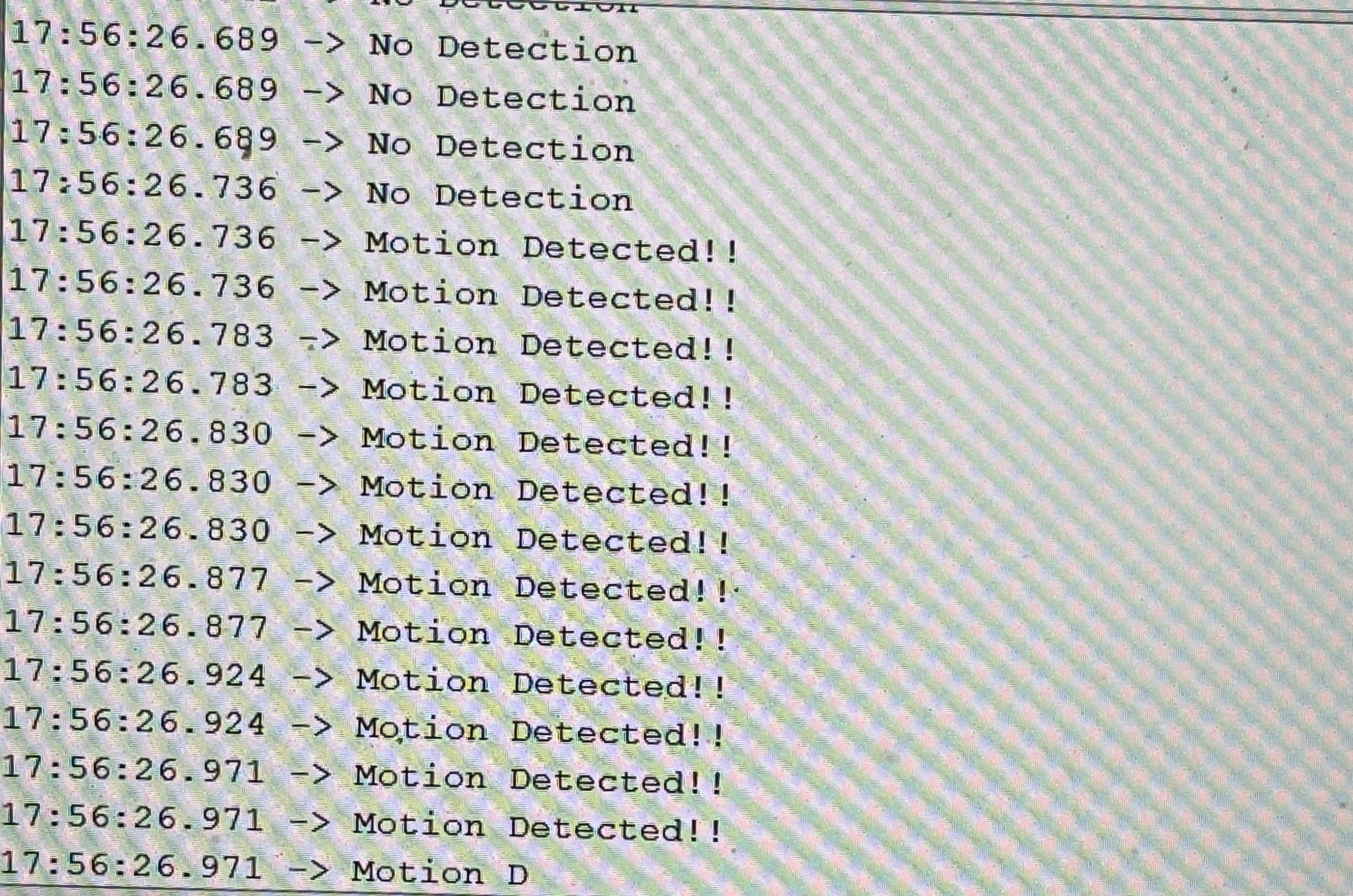
As you can see I started to get more accurate values, and decided that the neo pixels can wait for later, which is done during my final project week.
Here are some pictures to show consistency in my values;
Summary
This week was very long, although I understood after and learn many new things which I did not know. For example, I did not know what an FTDI (UART chip made by FTDI) was, although it turned out to be very useful to me and trying to network my project together.
Group Work
Jada, Andrew, and I used Pari’s Doppler Radar Sensor to test analog inputs. Jada helped wire the radar and connected the Doppler Radar using ground power and analog pins. Andrew helped set up the oscilloscope using this site they found while researching the sensor. Then I read the values off from the oscilloscope. We all took pictures, videos, and notes on how the oscilloscope functioned and how it connected to the sensor. We used the oscilloscope to help read whether the sensor was detecting movement or not. This is the result I recorded:
Here is the group site
Here are the filesfor this week