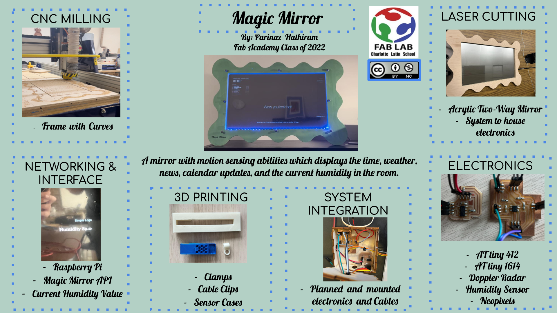
Magic Mirror
Here are the files for my final project.
Slide
Video
License Chosen

HTML Embedded Code
The Creative Commons License generator also gave me an HTML Embed Code, so I can display this symbol on web pages, to signify that I have a Creative Commons license.

This work is licensed under a Creative Commons Attribution-NonCommercial 4.0 International License.
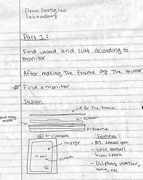
Initial Conception
A mirror is something you look at every day. Whether it is getting dressed, applying makeup, or even drawing funny shapes out of the fog. Whether you notice it or not an average person sees themselves in a mirror 8 times a day. To enhance this experience I wanted to make a Magic Mirror.
Expanding My Project To Target Groups for Awarness
To tackle another current issue, which this mirror will help fight and provide empowerment for are for people who struggle with an eating disorder. Eating disorders are serious mental health problems and can lead to major health consequences. People with an eating disorder experience negative effects on their organs, life-threatening brain-based illnesses, and even social isolation. Millions of teenagers struggle with an eating disorder, and a major contributor to this illness are social media platforms such as Instagram, Facebook, Twitter, etc. Many teenagers see perfect bodies and hateful words toward indicates who do not have the “perfect body”. Although, there is no such thing as a perfect body. Everybody is unique and that’s what makes every single person special. To conform to society has been the norm for many years, although this generation is slowly evolving and changing to be nonconformist, to stop caring about what others think. In honor of eating disorders, I would like to dedicate this Magic Mirror. The “Magic” of the mirror is to see that different is beautiful/ handsome, and there should be no strict criteria about how one should look. The software in the API automatically produces encouraging compliments which display on the screen. These few words can make a difference to someone even though it may not seem much.
As a teenage girl who has struggled with body image her entire life, I would like to start to create a change so that girls like me would think differently and be comfortable in their skin, and not need to change themselves to be someone they are not. The purpose of this project is to embrace individuality.
What will it do?
A Magic Mirror is a smart interactive mirror that displays (on the mirror) the weather, time, latest news, compliments, the current humdity, etc. It uses motion sensing abilties to sense a person and power the monitor on/off as motion is sensed.
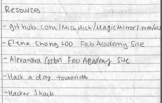
Who’s done what beforehand?
There have been many online applications and Open Source websites that have produced applications for magic mirrors. Here is the one I will be using: Magic Mirror API
This project has also been done by Fab graduate Elena Chong Loo in 2018 when she a magic mirror open source software, like the one I have used. Although, her project does not uses AI Responsive technologies, such as voice recognition and text to speech; something which I would like to do in the future to improve my project. Though, her project uses sound reactive Neopixels which is something unique and very cool. I was inspired by her project and wanted to take it to the next level, especially with the newer technologies which we have today.
There are also many versions of the Magic Mirror made online by various people, all having components that are unique and different from others. This project, although, has been made from scratch, for example, CNC Machining, PCB Design, Manufacturing,etc.
What will you design?
For this project, I will be working from scratch, except for using the Magic Mirror API.
I will be designing:
-
The frame and box in which all the components reside, will use the CNC. (Computer Controlled Cutting)
-
The acrylic for the two-way mirror (Laser Cutting)
-
Clamps to hold the monitor in place (3d Printing)
-
Custom PCB Board for the Neopixel and Motion Sensor (PCB Production and Design)
-
Vinyl Stickers for aesthetic design (Computer Controlled Cutting)
-
The environment of what the monitor will display; written through java script (Interfacing)
-
Writing customized code as modules in the software to update Sensor Values (Interfacing)
-
Connecting both my boards for Motion sensor and Humidity to read serial through a Raspberry pi (Networking)
What materials and components: Used? Cost? Come From?
BOM
| Materials | Quantity | Where to Get | Cost | Process |
|---|---|---|---|---|
| Wood for Mirror Frame | 1 | Found at Lab, and bought at Lowes | $26.68 | Computer-controlled machining |
| Acrylic | 1 | Found at Lab, and bought at Amazon | $21.99 | Computer Controlled Cutting |
| Two-Way Mirror Film | 1 | Found at Lab, and bought at Amazon | $11.99 | Final Project |
| Wooden Shelf | 3 | Found at Home, and bought at Ikea | $315 | Final Project |
| Flex Tube | 1 | Bought at Lowes | $3.28 | Final Project |
| Hex Nut Bolts | 8 | Bought at Lowes | $4.24 | Final Project |
| Raspberry Pi 3 B+ | 1 | Found at Home, and bought at Adafruit Companies | $35 | Final Project |
| AtTiny 412 Chips | 1 | Found at Lab, and bought at Digikey | $0.64 | Electronics production & Electronics design |
| DHT11 Humidity Sensor | 1 | Found at Lab, and bought at Amazon | $2.09 | Interface and application programming & Input devices |
| RCWL-0516 Doppler Radar | 1 | Found at Lab, and bought at Amazon | $11.99 | Input devices |
| Neopixels | 1 | Found at Lab, and bought at Amazon | $24.69 | Final Project |
| Monitor Display | 1 | Found at Lab, and bought at Amazon | $129.99 | Interface and application programming & Final Project |
| TV Mount | 1 | Bought at Amazon | $26.99 | Final Project |
| Spary Paint | 1 | Bought at Micheals | $7.99 | Final Project |
| Power Strip | 1 | Bought at Lowes | $5.38 | Final Project |
What parts and systems will be made?
All the electronics such as the inputs and outputs will be made to fit together in the final project through custom PCB milled boards and networking through the use of I2C and microcontrollers (AtTiny 412 chips). To
To have an interesting and non-traditional frame for the mirror, I designed a CAD Model and CNC cut the frame. If time permits, I plan to paint this mirror frame. The frame will also have a wooden enclosure to house all the electrical components such as the monitor, inputs, outputs, etc. This enclosure will be made through planks of wood which will be cut in rabbit cuts to ensure that the box is stable.
Lastly, focusing on the mirror display. This code will be written my Magic Mirror API in javascript, and I plan to add a custom-coded module in python which will actively update the humidity of the room
What questions need to be answered?
Do I have enough components electronically for this to meet Fab Standards?
How will it be evaluated?
This project should be evaluated on its convenient and sleek functionality in everyday life. Mirrors are everywhere, but it is time to step- up the game and make them electronic to empower people every day when they wake up.
I would also like my mirror to be graded on the evolution and change/ how it has improved over time through various ideas from people and different projects.
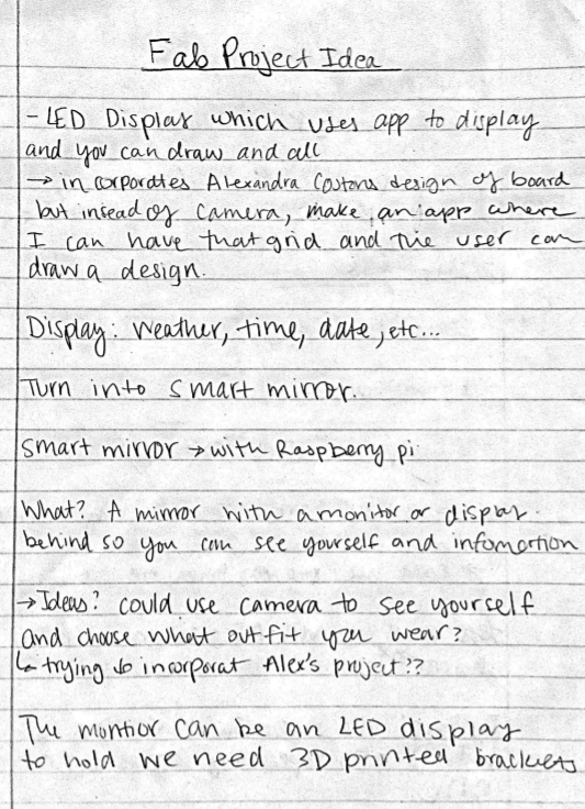
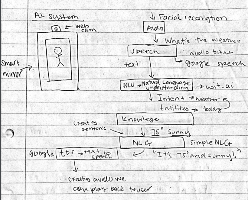
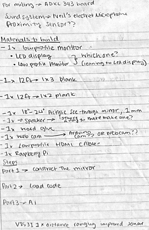
Initial Plans
To go more into detail check my Week 1 page!
Here are some sketches of my planning and design process:

CNC Milling
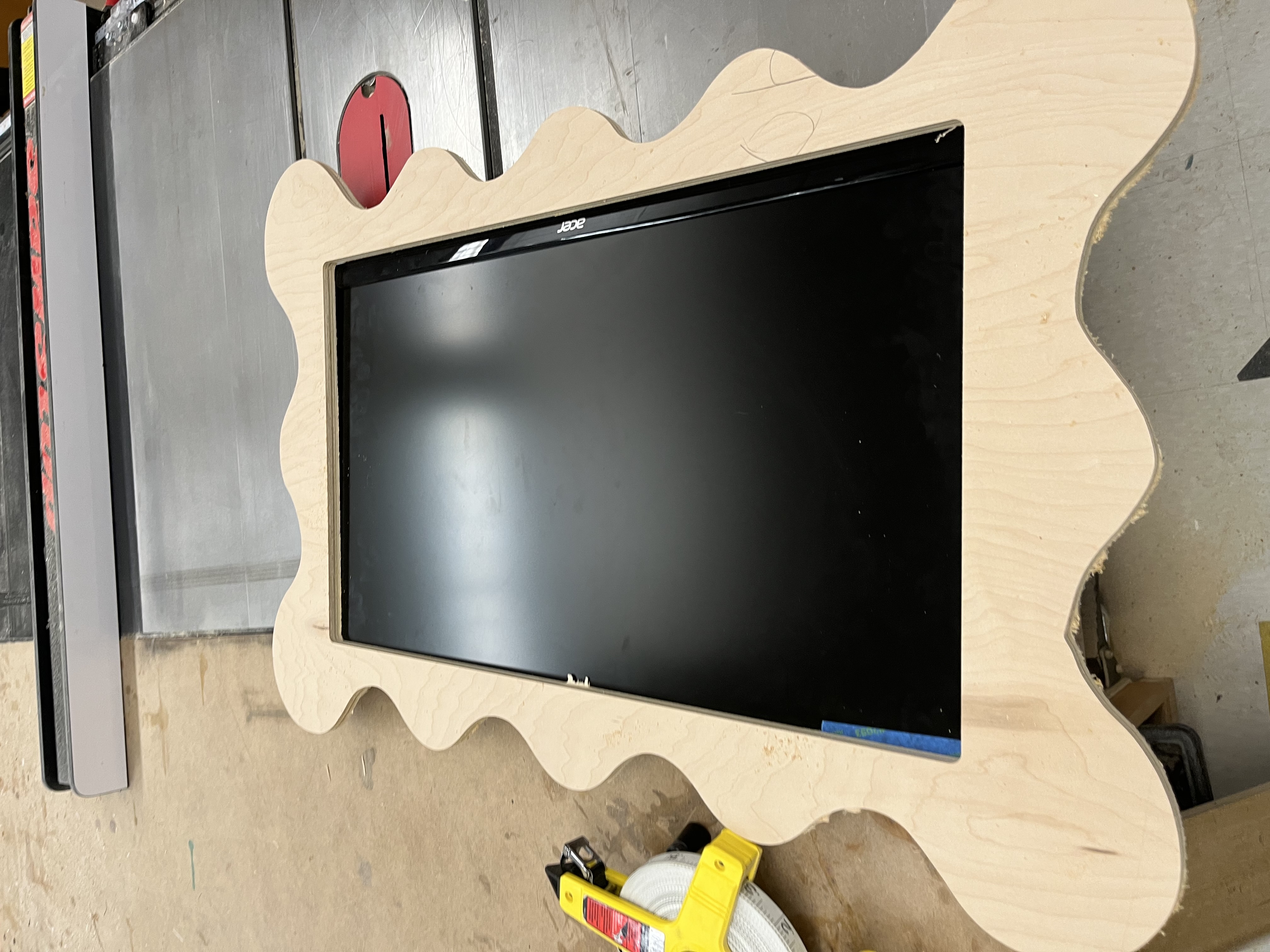
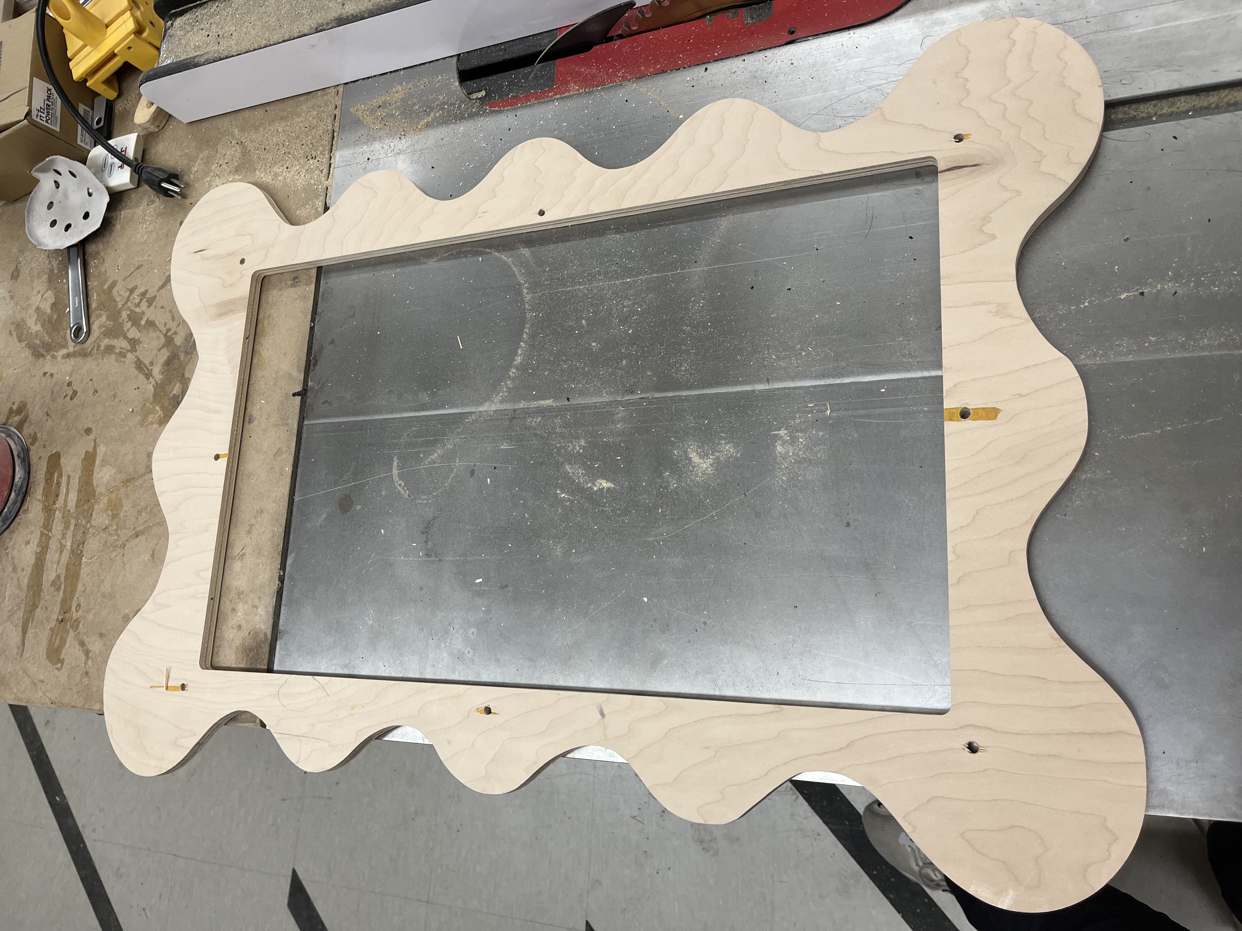
For the frame of the project, I made a non-traditional mirror frame. In my Week 8 Documentation, I started building this frame. Although, now my skills have become much more efficent and neat. To design the frame for the final project, I used Cuttle to start my 2D Design. Since my drawing skills are not the best in the entire world, I imported an.SVG so I could trace it for a better resolution.
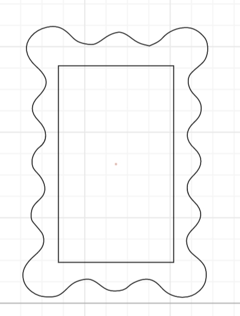
I first imported an.SVG from the internet, and then imported it into Cuttle. Then deleted the outer part of the.SVG so I would only be left with the wavy outline.
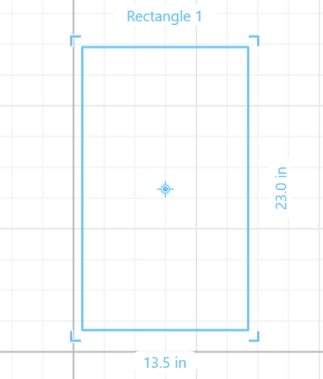
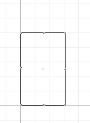
Next, I measured the dimensions of the monitor and then designed a 23x13.5 rectangle which will be the opening of the frame, or where the monitor and two-way mirror will be shown. Here is what it looks like.
Next, I put together the rectangle and the wavy frame and tried to center both of them, so they are in the position of how I wanted them to be cut. And then exported this as an.SVG and imported it into Aspire.
I also designed a model on Fusion 360, for better visualization.
Here is my fusion 360 file:
Testing on Laser Cutter
Before using the CNC, I decided to test my design on the laser cutter just in case there was a mistake. This is so I would not waste any time and resources if there was a mistake. Just as I did in my Week 8 documentation I followed the Workflow of the Fusion Pro 48 Laser Cutter, and cut my design.
This was an easy process, although I had to scale down the size of my mirror since I did not have bigger-sized cardboard. Learning from my mistakes from Week 8, this was a much smoother process, and my cut was sucesfull the first time.
Frame Design In Aspire
Importing into Aspire was easy and the entire process was easy, as I had done it before during Week 8, so I referred to this documentation through the final process of my frame.
In Aspire, I imported mine.SVG, and created 2 separate profile cuts. This was so I could easily manage each part and there was a lower chance for failure. Instead of creating pocket cuts like last time, I found a more sleek way of integrating my components.
Machine Settings in Aspire
The material settings were similar to last time, although the thickness of my wood was different. Instead of having such a heavy frame, I decided to use half (0.5) inch thick wood.
The material dimensions of the shopbot: are 96x48 inches.
The thickness of my material: is 0.5 inches.
To determine the thickness of my material, I used a caliper, to get the precise measurement.
Due to variations and human error, I set the zero to be from the machine bed. This is so the machine would recognize not to cut itself (the bed). I also calibrated the Z- axis of the machine bed since this is a profile cut.
Toolpaths in Aspire
To set up tool paths, you can refer to my Week 8 documentation. There is a step-by-step guide as to how to set up tool paths which would be beneficial to follow if you do not know how.
Cutting Frame of CNC
This process was also easy, but there is no room for error, so I did these steps meticoulsy and slowly to avoid any error on my end.
I used the CNC Cutting Workflow to make this a safe and smooth process.
Setting up the CNC
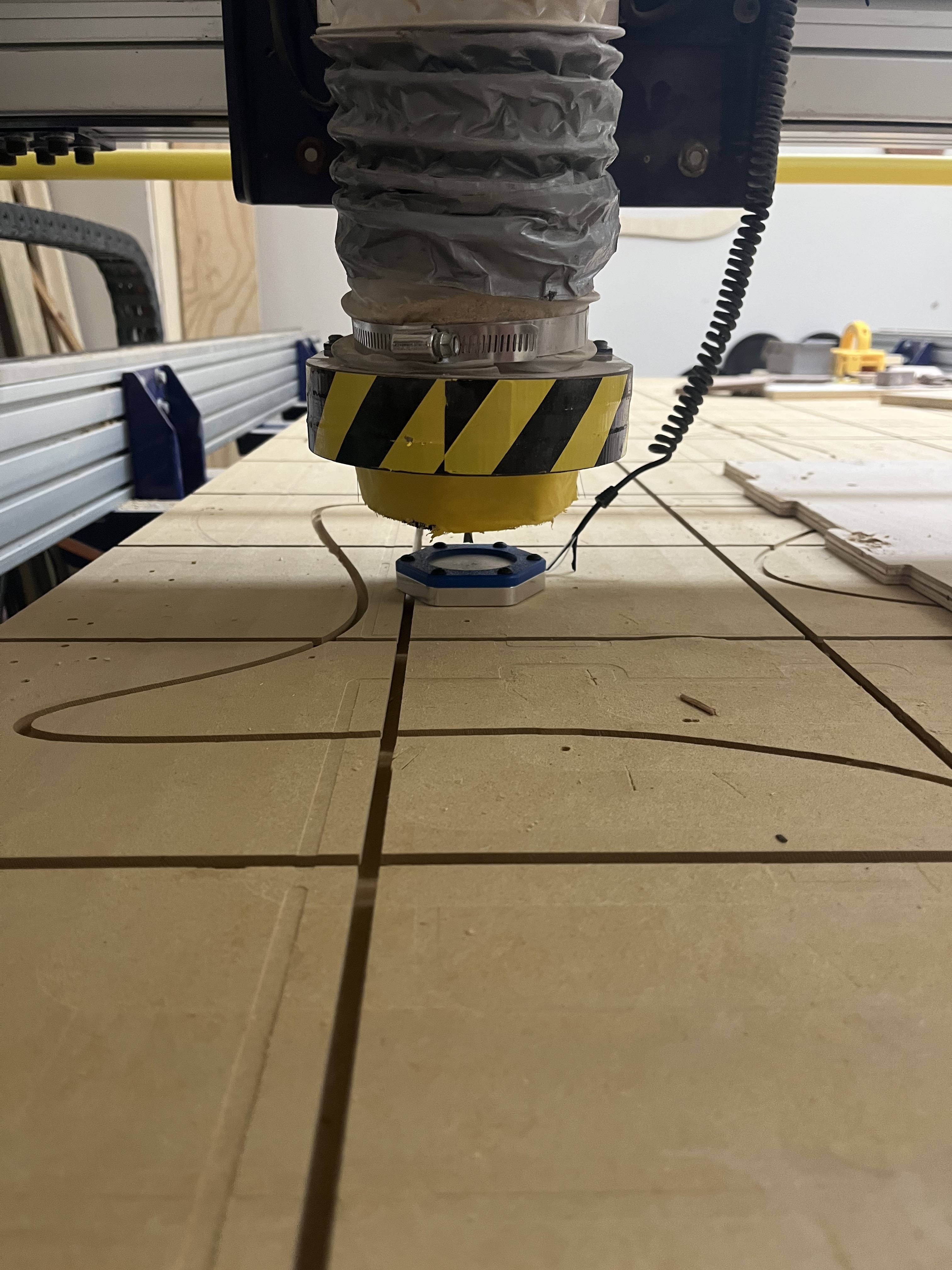
Aircuts
CNC Profile Cuts
Rectange Profile Cut
Wavy Profile CNC Cut
Final Result (Before Post-Processing)]
Post Processing
To post process, I sanded down my mirror, so there weren’t many rough edges and surfaces. This is crucial so your frame all looks like one piece. It is also important to sand down wood before your pain it. That was going to be my next step. I used different grit sandpaper, ranging from 60- 1200 grit. I slowly worked my way up from the different grits. This process took a while, although it was a very rewarding experience. To learn more about post processing go check out Week 8 of my documentation, where I CNC cut a frame.
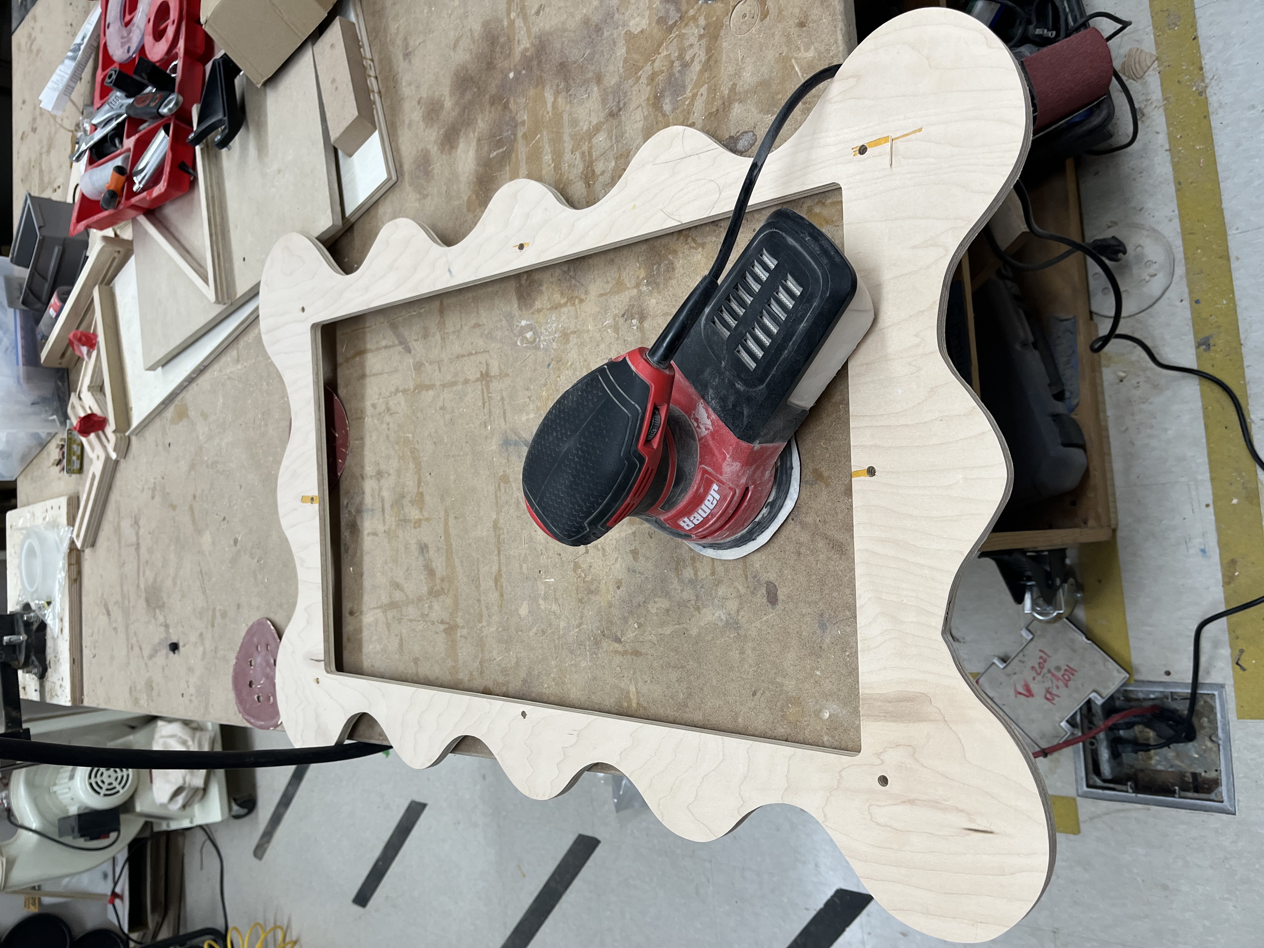
Video of Sanding
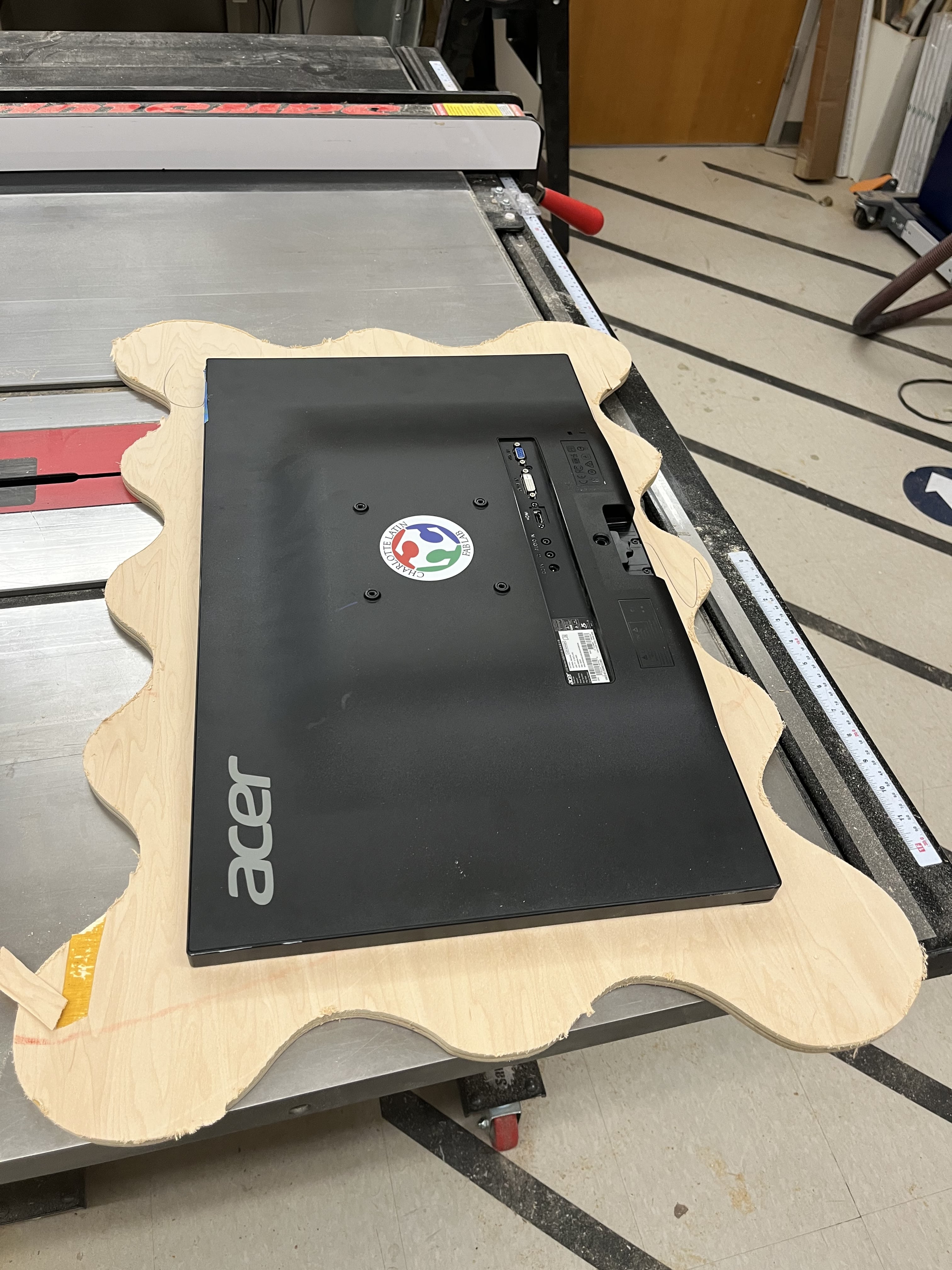
Final CNC Cutt Frame
Painting the Frame
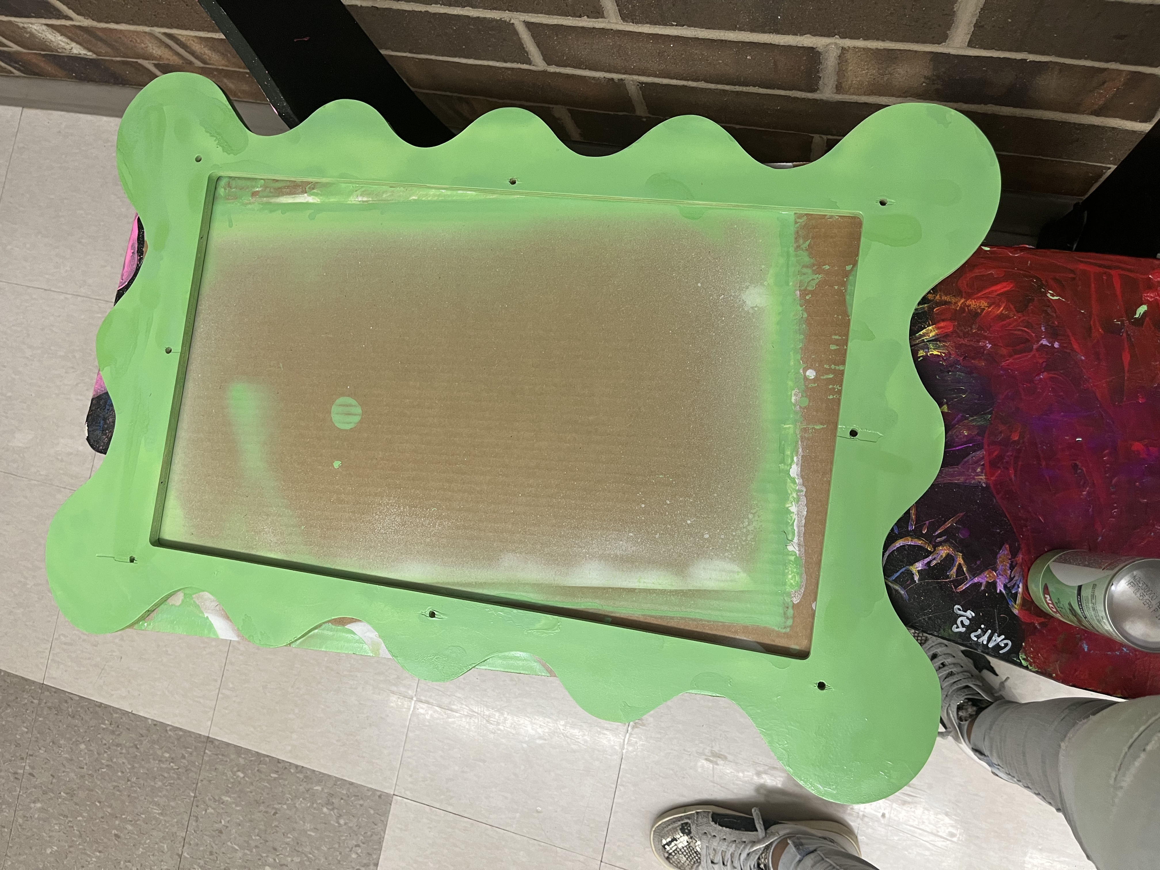
Painting the frame, was one of the parts I was looking most forward to. I already had a vision of what color I would paint the frame. I envisioned a Matcha Green color or Sage Green color. The reason I wanted to do this color is that It looks trendy, matches my bathroom, as well as it serves the purpose of the awareness part of this frame. The colors that symbolize eating disorder awareness, are Green and Blue. Painting the frame took ~ 40 mins. This seems like a long time just to paint a frame although there was a lot of prep working that went into it.
I sectioned this part of my project into 4 parts.
1 . Prep all the materials such as primer, spray paint, cardboard, and camera. As well as, read all the instructions carefully before starting.
2 . Go outside, set up everything, and spray paint some primer onto the frame. and wait 2-3 mins between each coat. After all your coats are done, wait 20 mins before spray painting.
3 . Once 20 mins are done, Start spray painting. Have equal strokes, and don’t layer paint on top of,k it will cause even paint strokes.
4 . Let the paint dry for over an hour, and your frame is successfully painted!
To document this, I took a timelapse of me doing all of these steps.
Applying Primer onto Frame
Applying Paint onto Frame
After painting the Frame, I was scared that the color was too bright, although I thought maybe it will fade a little and become the color I want once it dried, and that’s exactly what happened. I also think that the lighting in this picture is a little too bright.
Mirror freshly painted
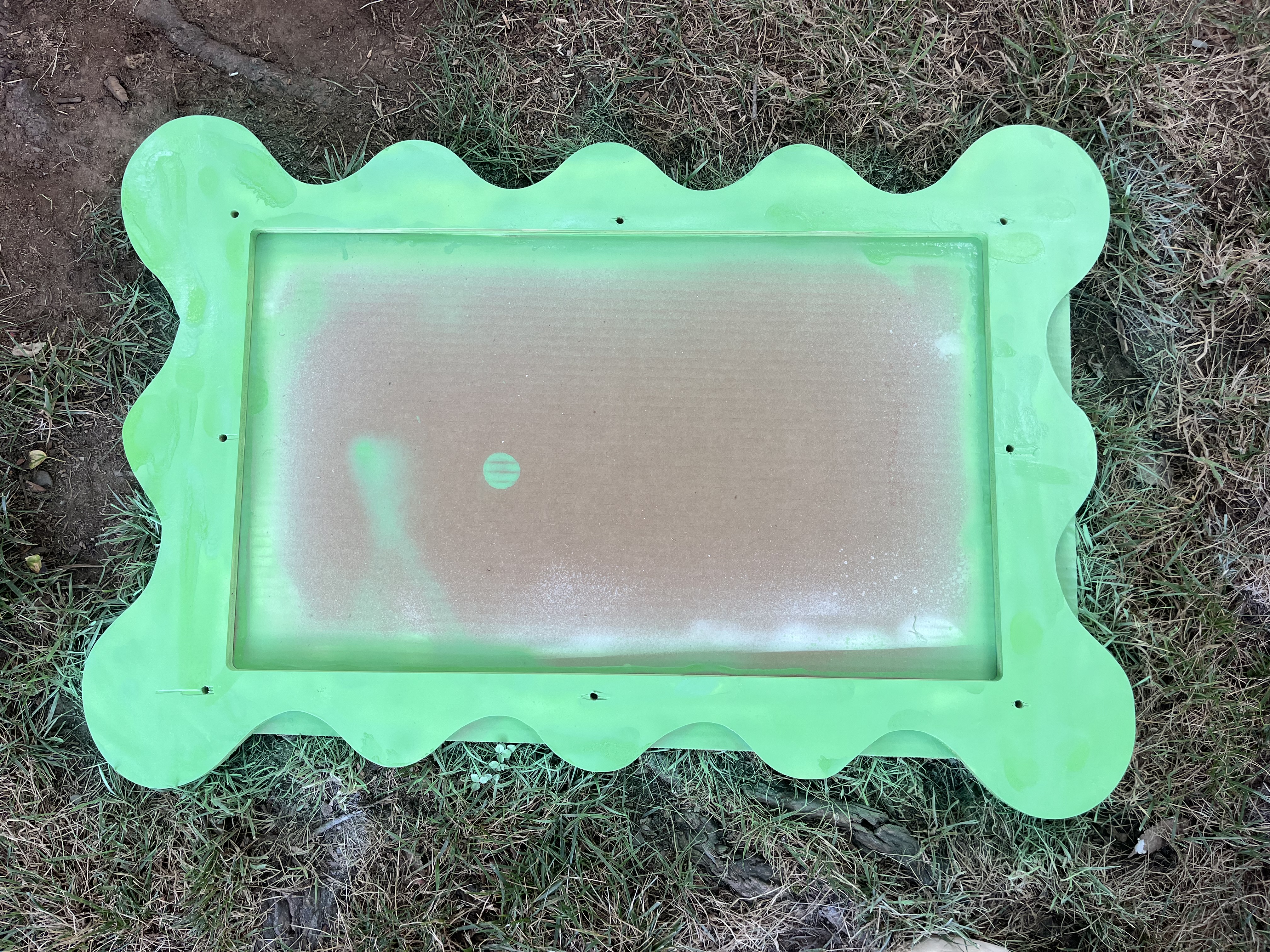
Final Painted Mirror after Drying
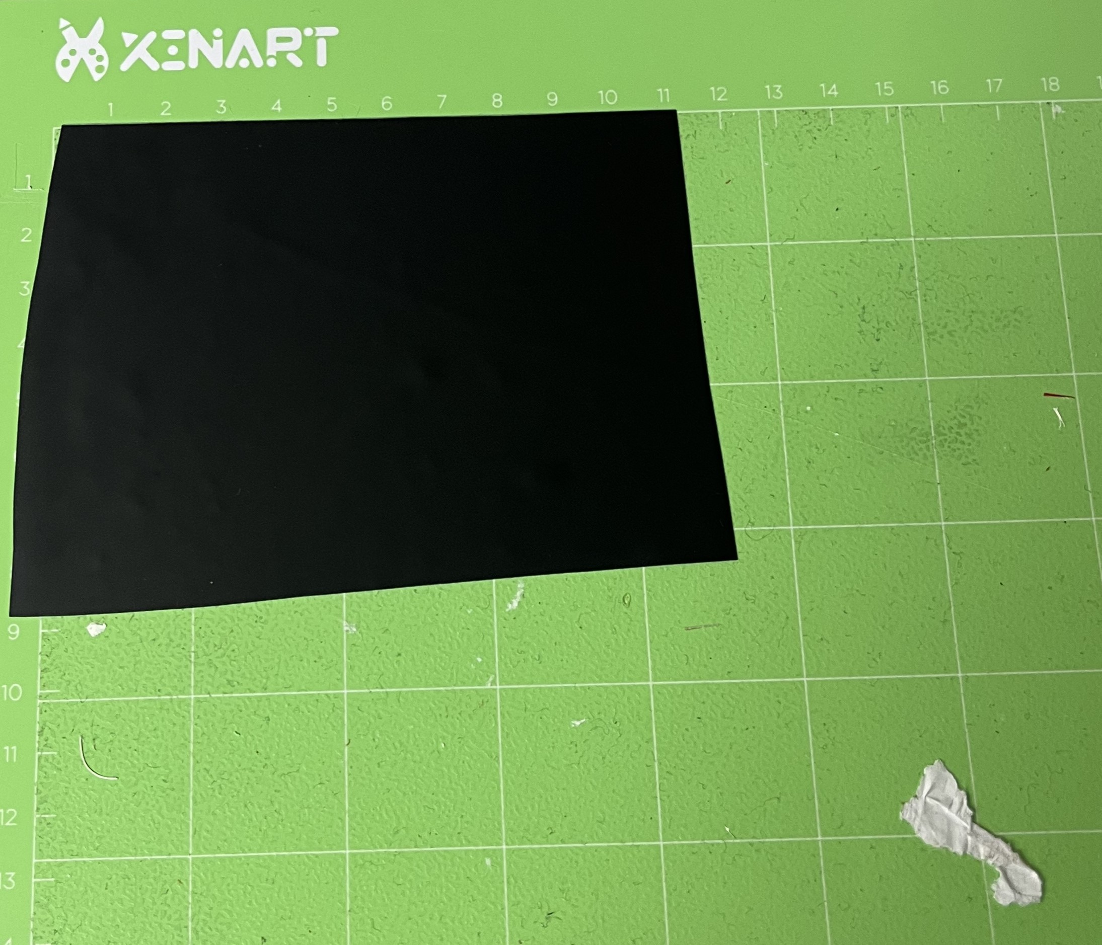
Creating The Two-way mirror
This should have been a very simple process although, I did not have the correct materials that first time. I did this twice. The first time did not go as planned, although that’s fine. It was a learning experience.
Results of the first time
I broke this process up into 3 steps:
1 . Find acrylic and use the laser cutter to cut out the dimesiosn needed.
2 . Design holes which would be used to screw the acriyic into the mirror frame.
3 . Place the two-way film on the mirror to create the mirror affect.
Plan/ Design the Acrylic Dimesnions
Instead of buying a two-way mirror, I decided to make one myself becuase they are very expensive. My first plan to do this was to use acrylic as the base, so I would have somehthing that the film could stick onto. This was a great idea, so I did some research to see how I could achive my goal. This research led me to some instructions on how to install a two way mirror film onto acrylic.
Instructables on How to Apply Mirror Film
It all looked very easy, so I decided to give it a try. Little did I know I would spend 4 hours on this. In my defense, I did not have the right materials, so the mirror tuenrd out unneat with many airbubbles and wrinkles.
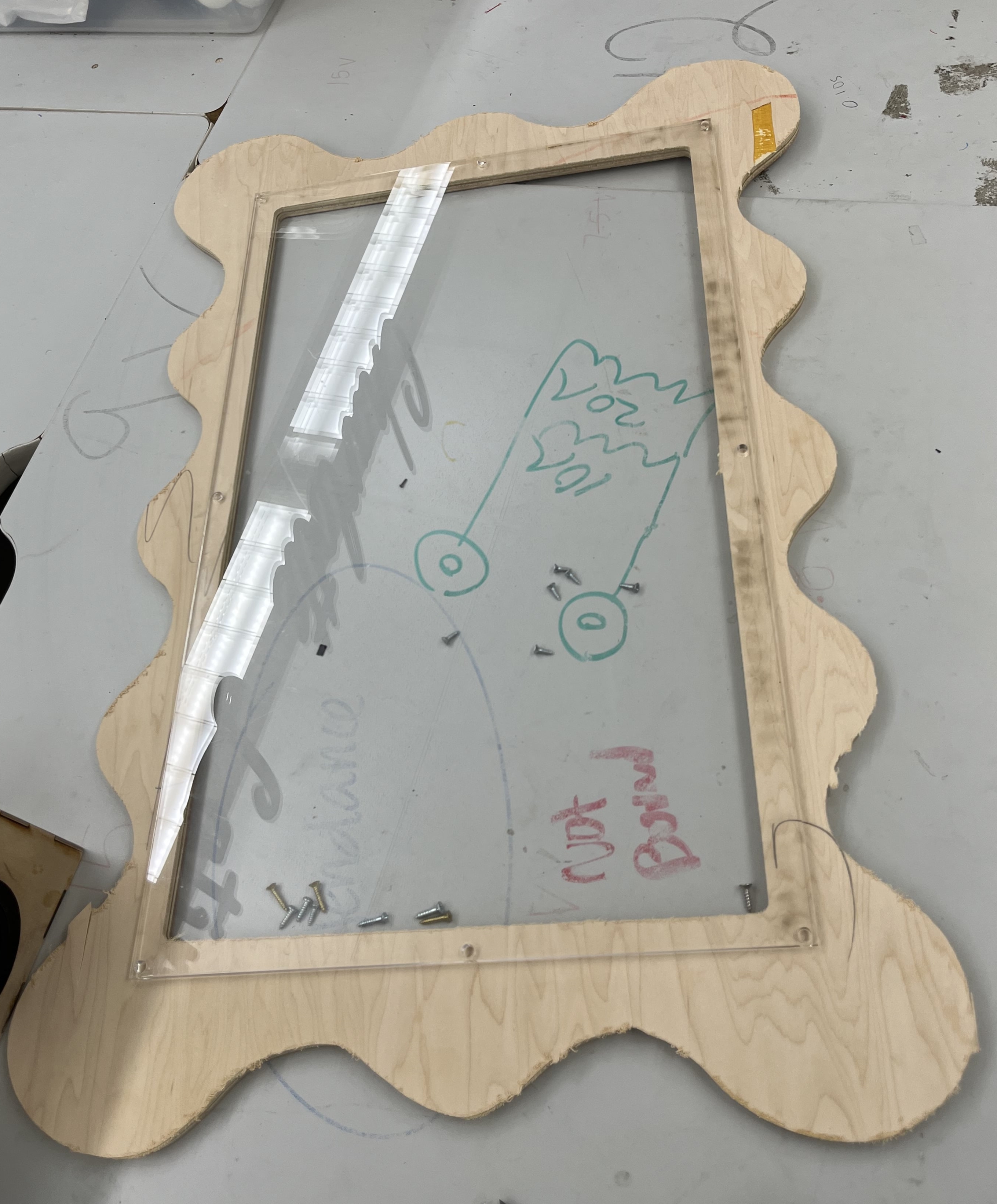
But before all of this, I used a CAD Software called Cuttle to design the dimesnions of my acrylic. I refered to the dimensions of the rectangular hole of my woodeden wavy frame and decided to make the dimensions 2 inches bigger, so the acryilic would have a strong base to screw in as well as, I accounted for space that my components box will need to fit in. After doing all this math and mesurement, I ended up changing the dimensions from 13.5 x 23in to 15.5 x 25.
This is what it looked like:
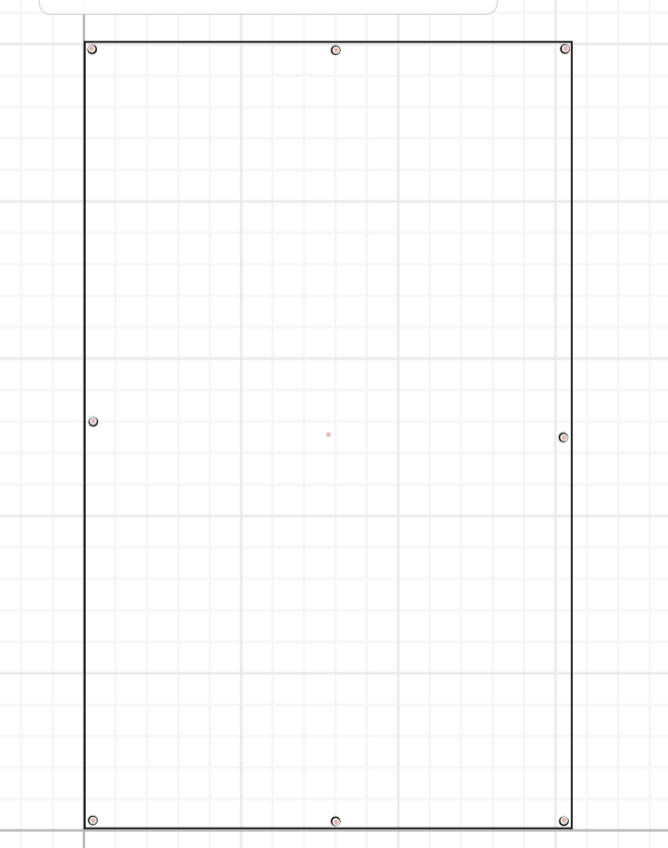
Next, I learned that acrylic will crack if I drill into it, so I decided to design some holes. I took screens that I knew I wanted to use and measured the diameter of them with calipers. I chose a specific length of screws so that they would not penetrate through the other side of the frame.
Once designing the holes I copy/pasted them, and placed them around the frame, which ended up looking like this.
Once all was designed and I was ready to begin, I chose the piece of acrylic I was going to use. Although we were running short of clear acrylic, so I had to scavenge for this piece. Ideally, I would have liked to choose a thinner piece than I did, but this was also fine, as it ended up working better than the thinner piece.
Using the Laser Cutter
The next step was to use the laser cutter. Since I was running low on acrylic, I decided to do many test tries, so I could get it right on the first try. I first cut it on cardboard, and this worked well, although I learned that my holes were too close to each other, so I changed my design and moved them a little farther apart.
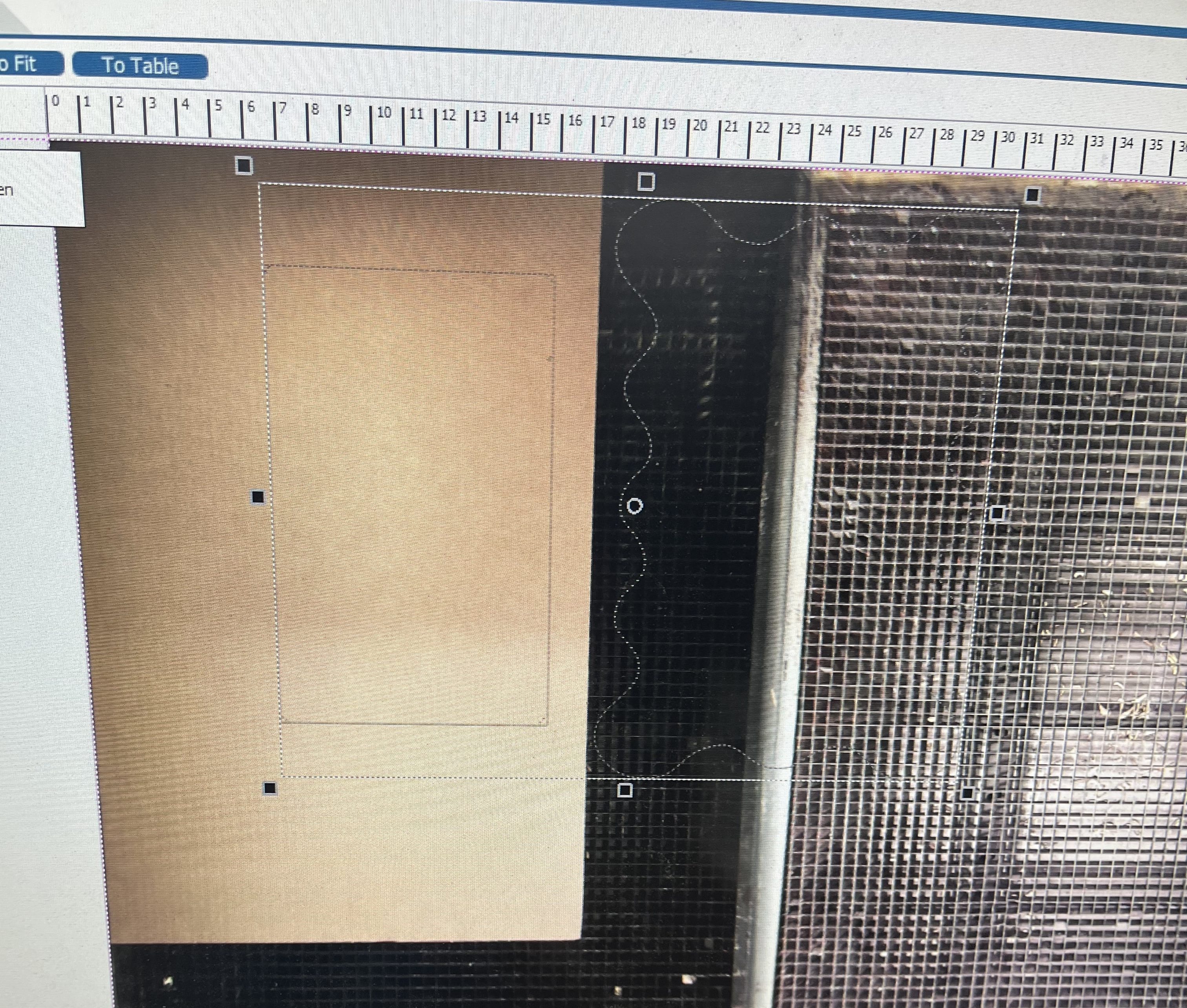
I exported my design from cuttle to CorelDraw and prepared for it to be cut on the laser cutter. Here is a picture of the design loaded onto the Laser Cutting Software.
To safely laser cutt, I followed this workflow:
Fusion Pro 48 Laser Cutter Work Flow
Here is a video of my cardboard test cut.
Next, I wanted to be extra precautious and decided to cut a smaller version of this on the acrylic to see if my mesurements for the screws were fine.
I followed the same steps as above, but the change changed the material. Here’s a video of the Practice acrylic, being cut on the laser cutter. After I knew this was right, I planned on starting to cut the final acrylic.
I then used this confidence to cut on the actual piece of acrylic. I followed all the steps and workflow guidelines to make me successful.
Here’s a video of the Final Laser Cutt Acrylic.
Mirror Acrylic
3D Printing Clamps and Clips
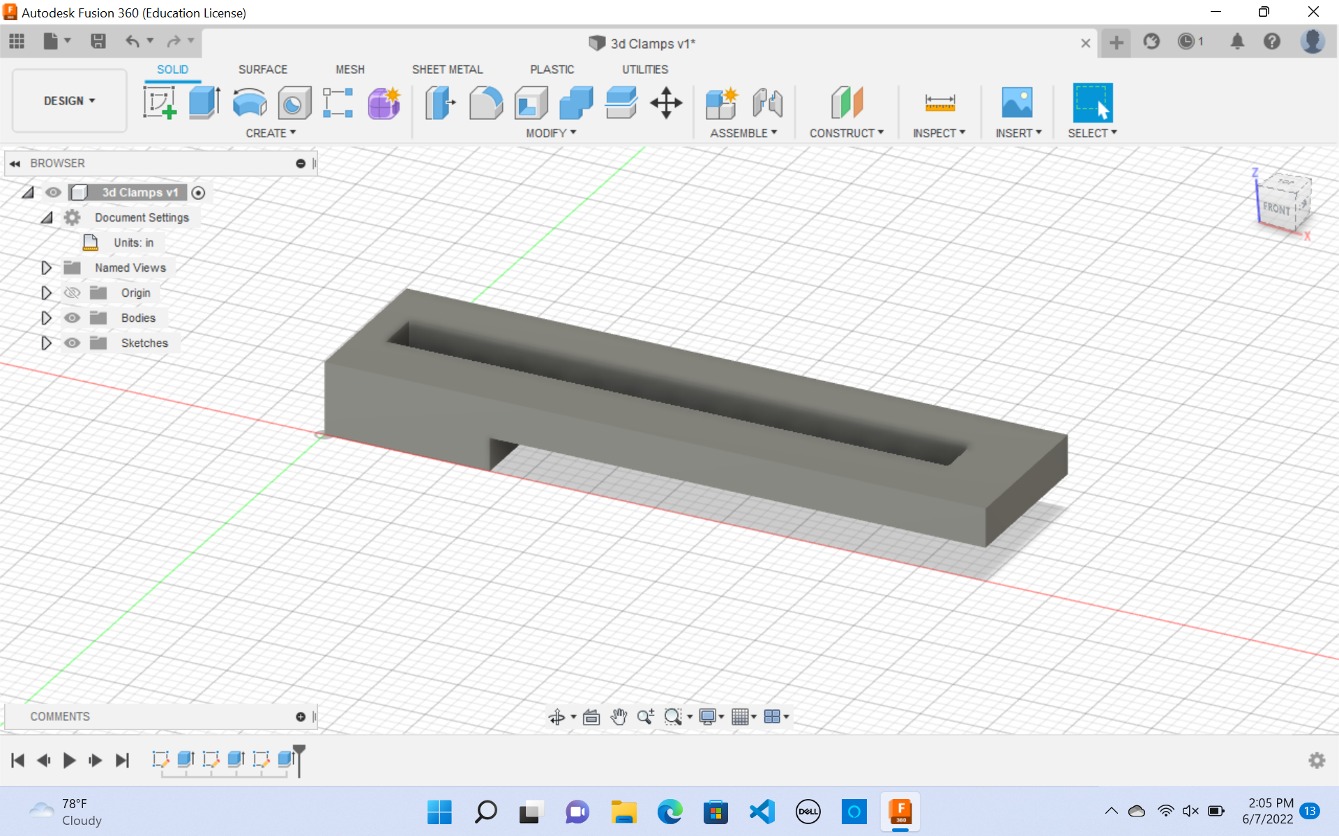
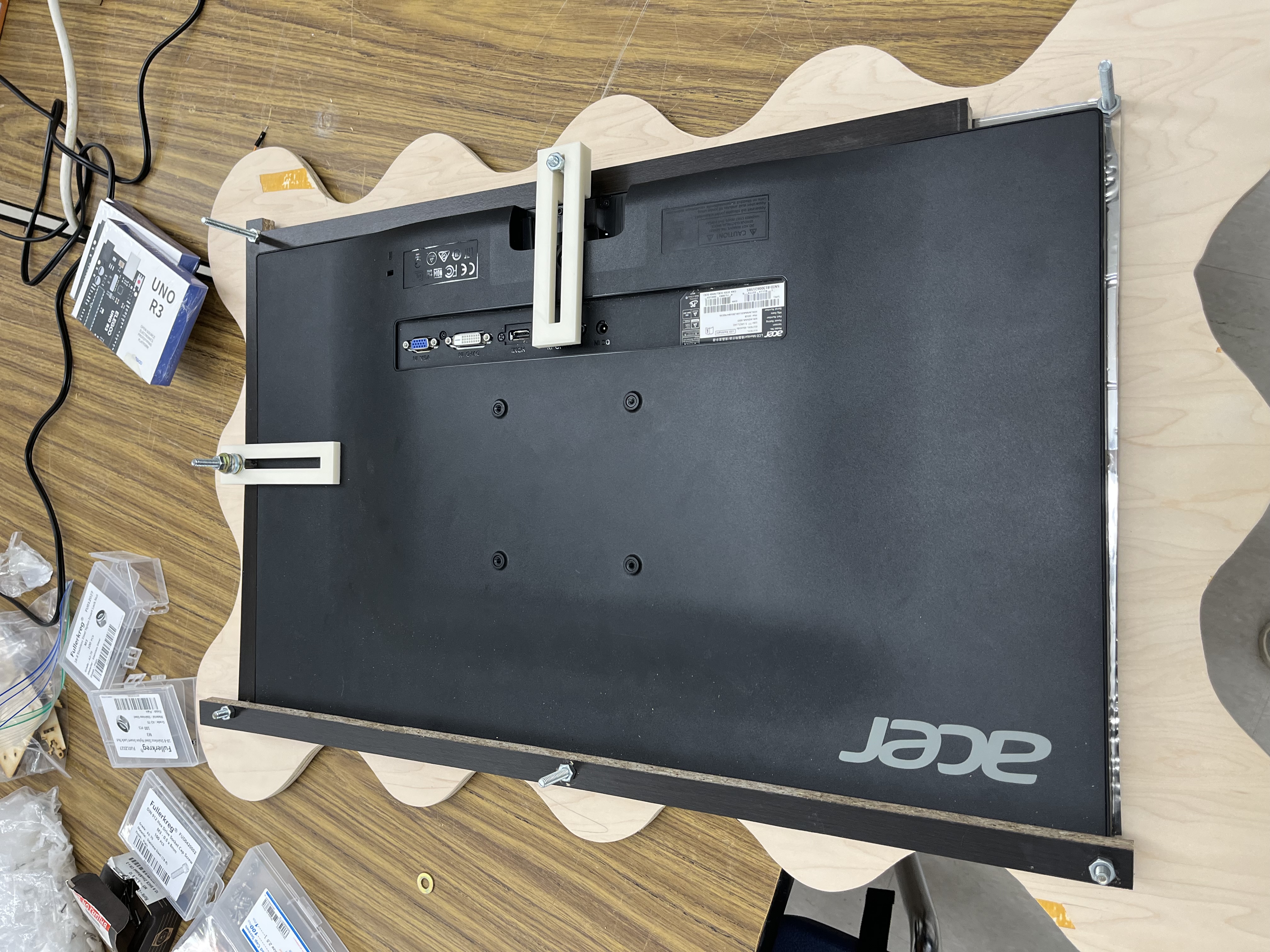
Another portion of my final project was to 3D print clamps to hold my monitor down. To do that, I first designed the clamps on fusion 360. I did this off the top of my head as I had a reference of what I wanted my clamp to look like.
I took constant measurements, and make sure that my clamps would fit my monitor ad that it can easily be moved around.
I used my week 3 documentation on computer-aided design to help me.
I used Fusion 360, as my CAD software, and started to design my clamps.
Here is my fusion 360 file:
By following my week 3 you can see the different processes I used to create my clamp.
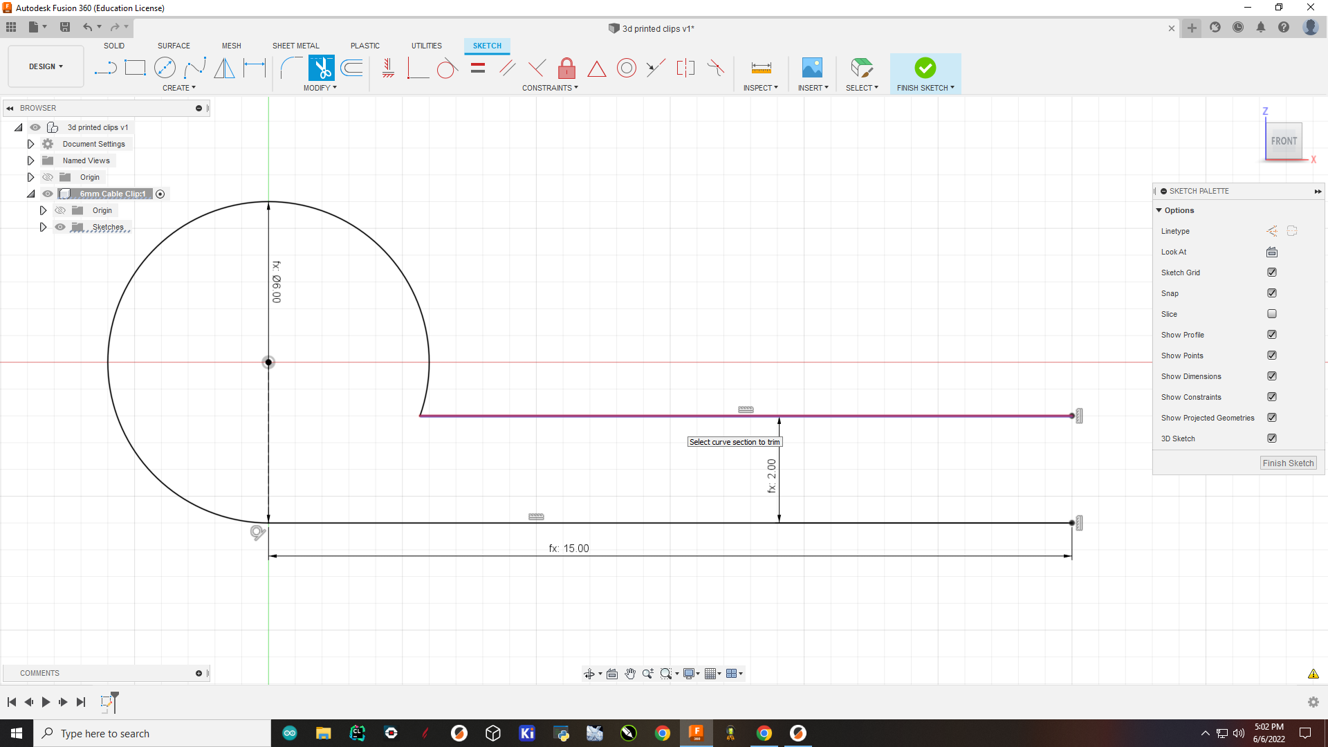
Here are the step-by-step processes I did to create my clamp on Fusion 360.
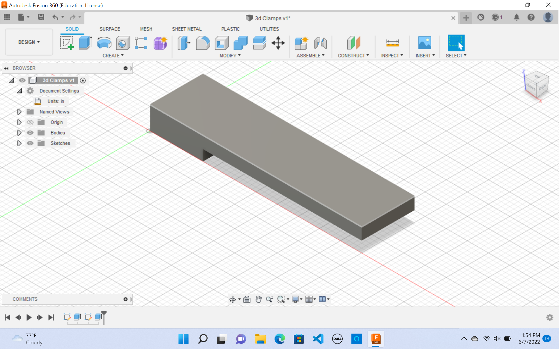
1 . I first created a sketch and then drew a rectangle of the dimensions above.
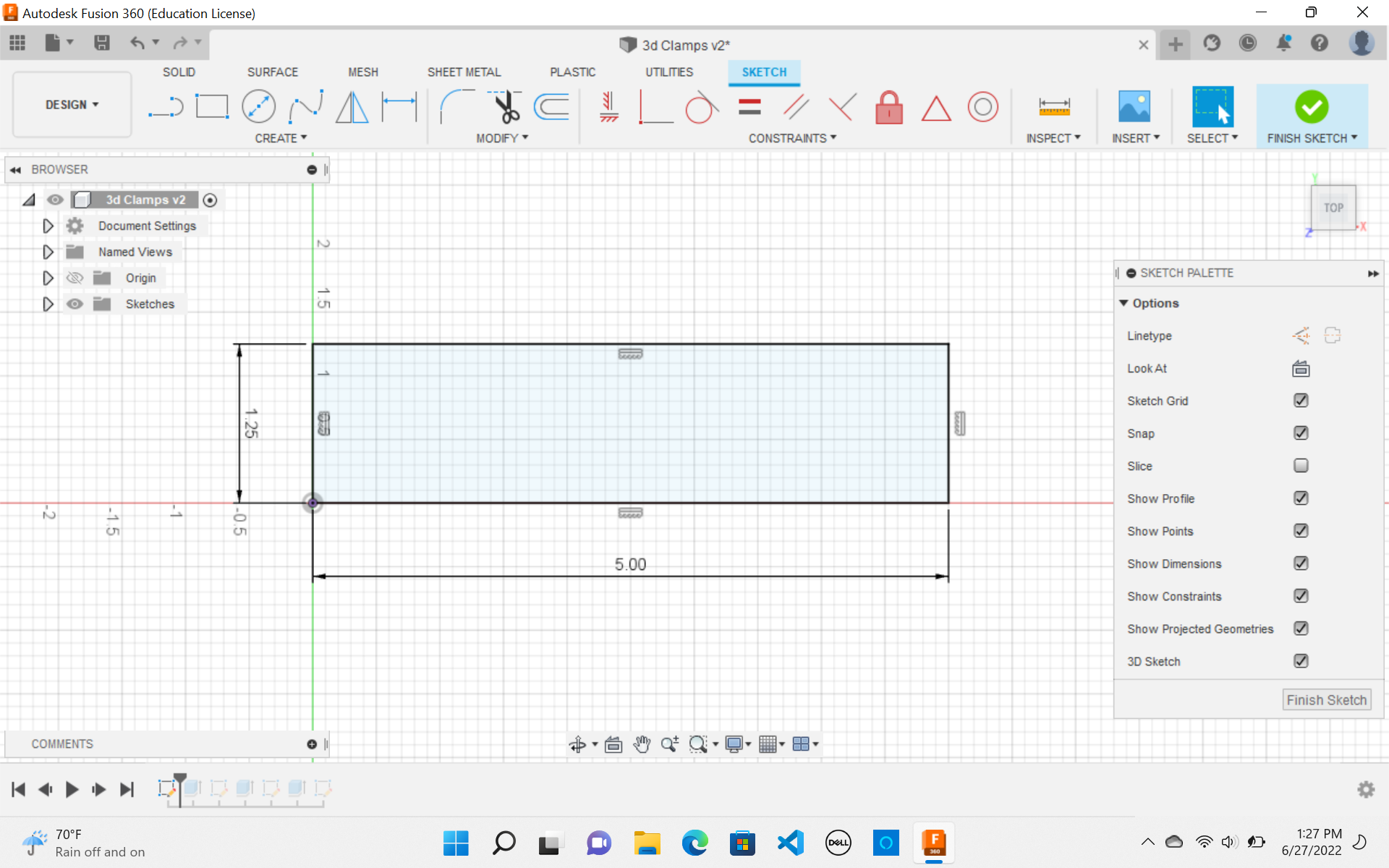
2 . Then I extruded the feature using the Extrude feature.
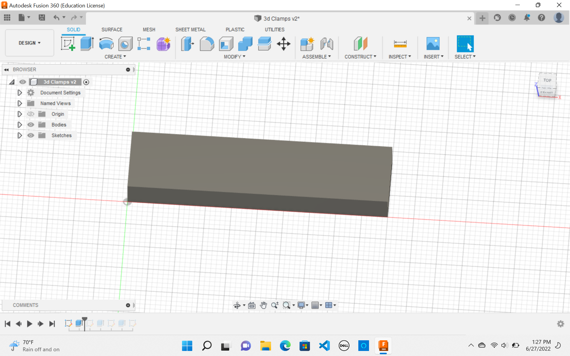
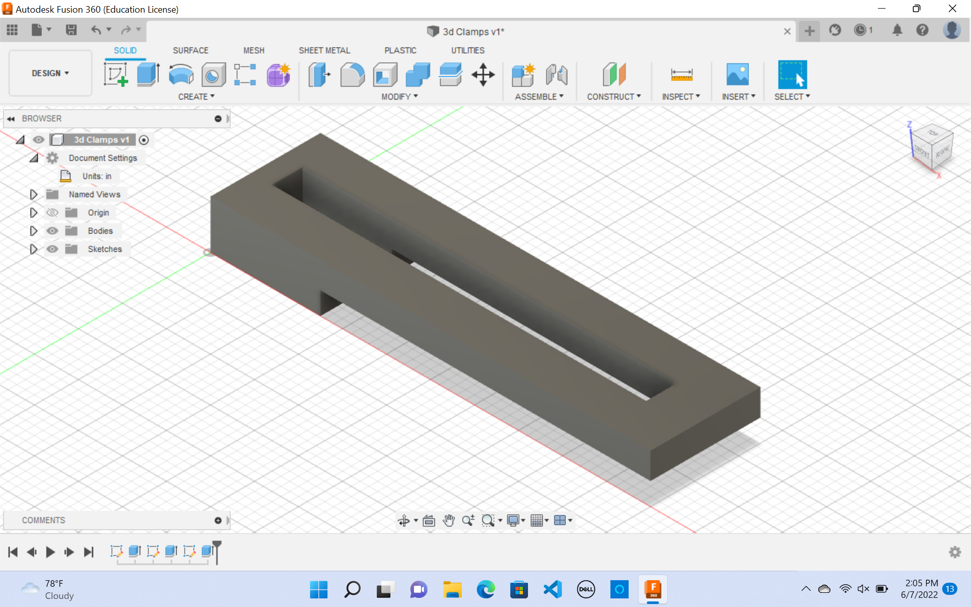
3 . Next I made another sketch for shaping the clamps. Follow the dimensions above.
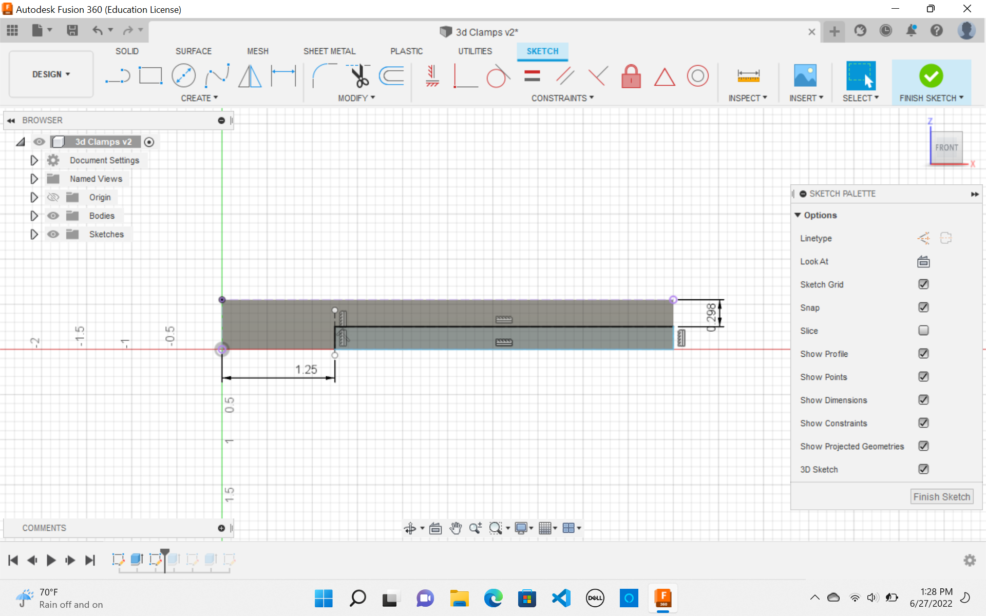
4 . Then I used the extrude feature to cut these dimensions out.
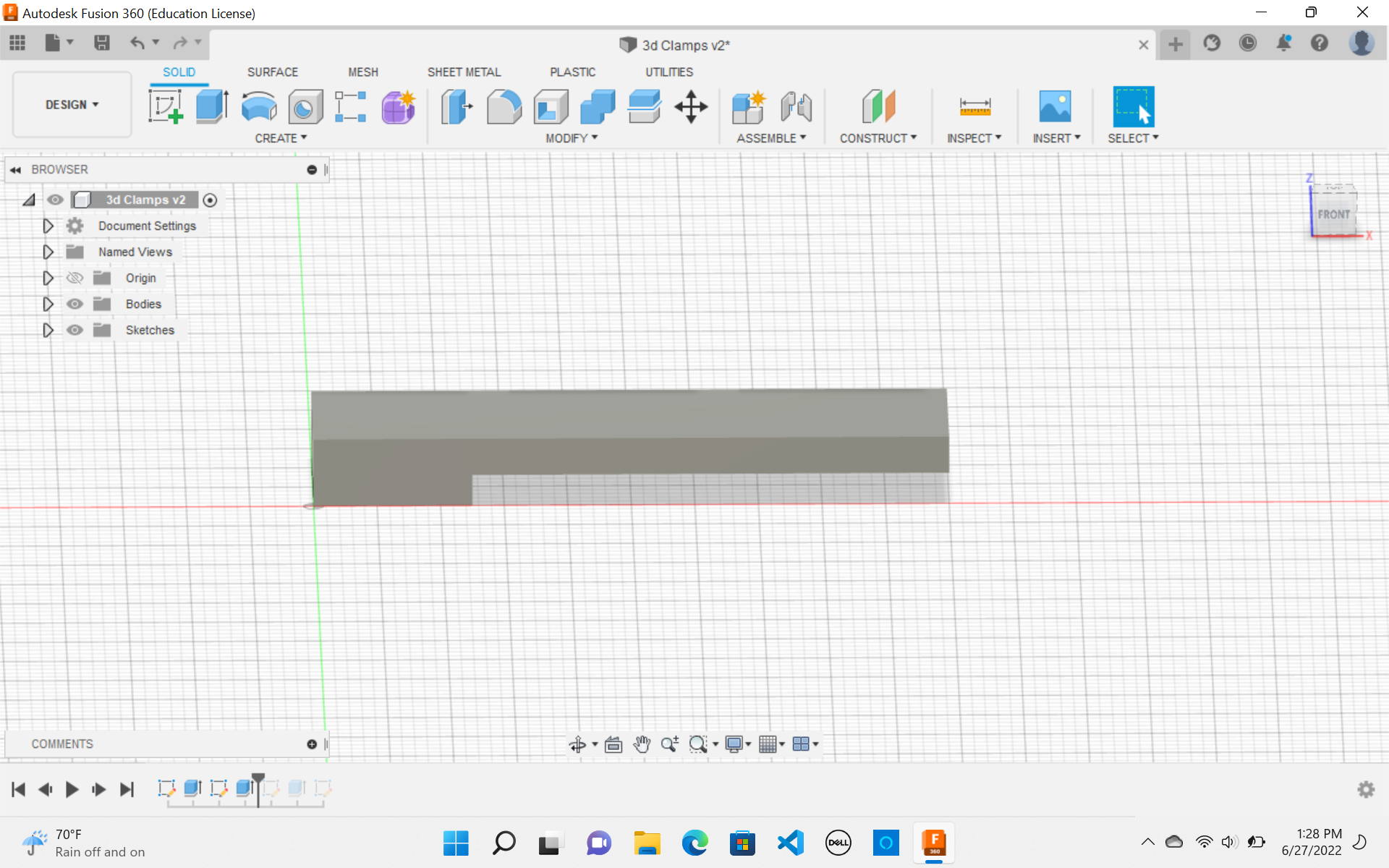
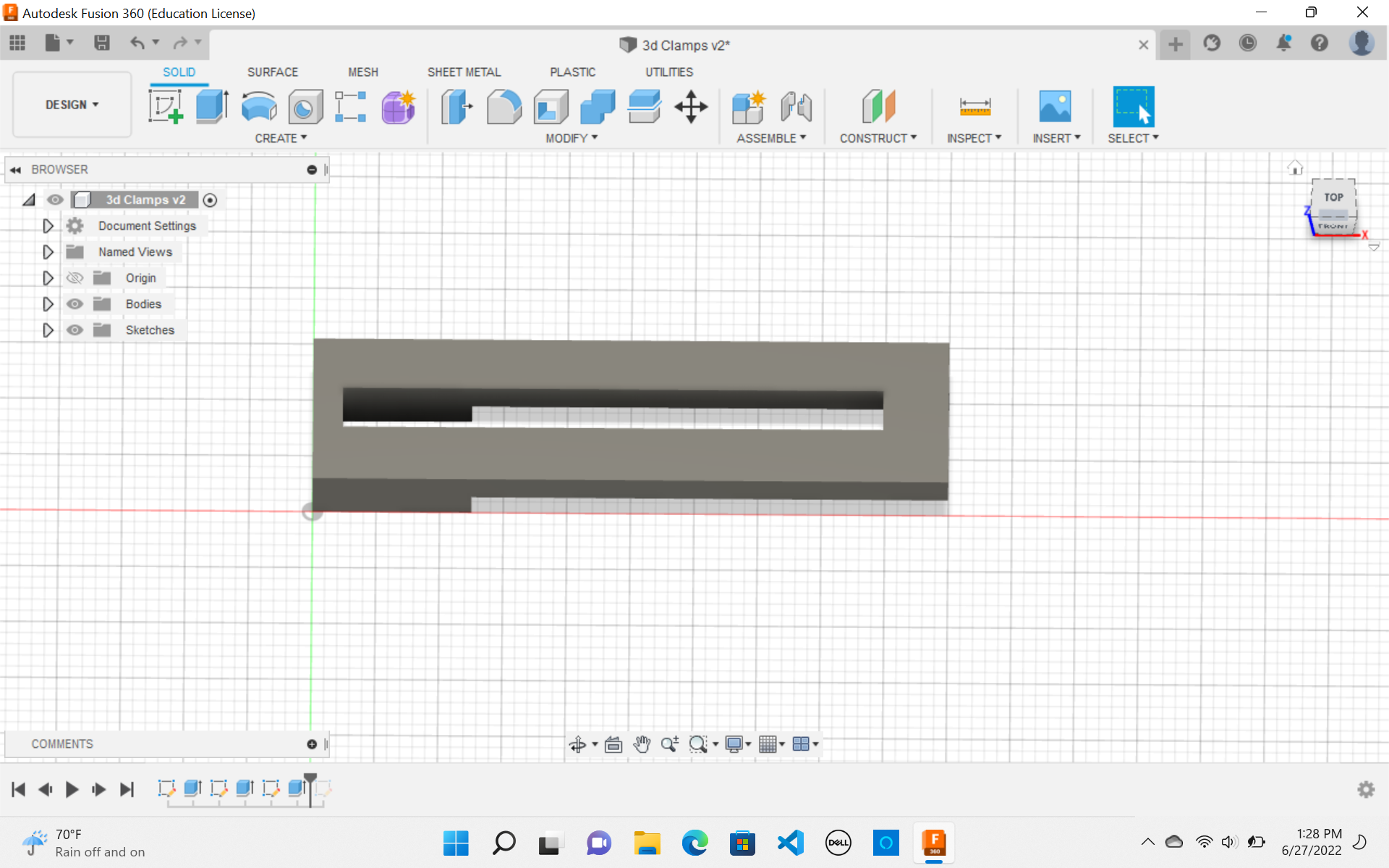
5 . I created a new sketch on top of the clamp to make a slit This slit would ensure that my bolt could slide back and forth so my clamp is adjustable.
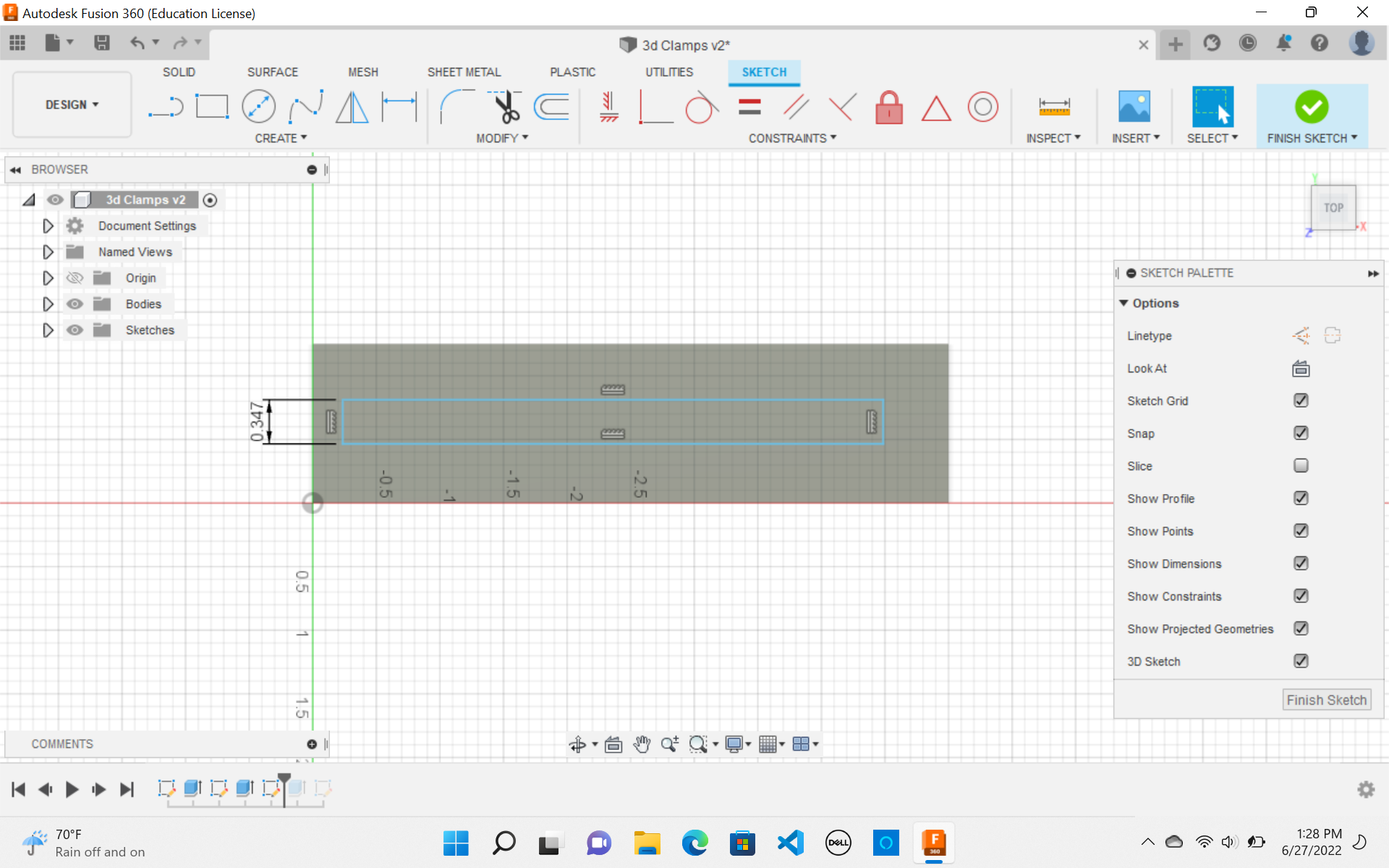
6 . I then used the extrude feature to cut these dimensions out.
My clamp was finally done!
Final Clamp CAD Designs
I then used my week 6documentation to 3d print my clamps.
Here is what it looks like on Prusa SLicer
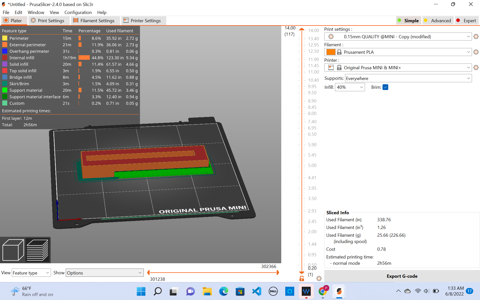
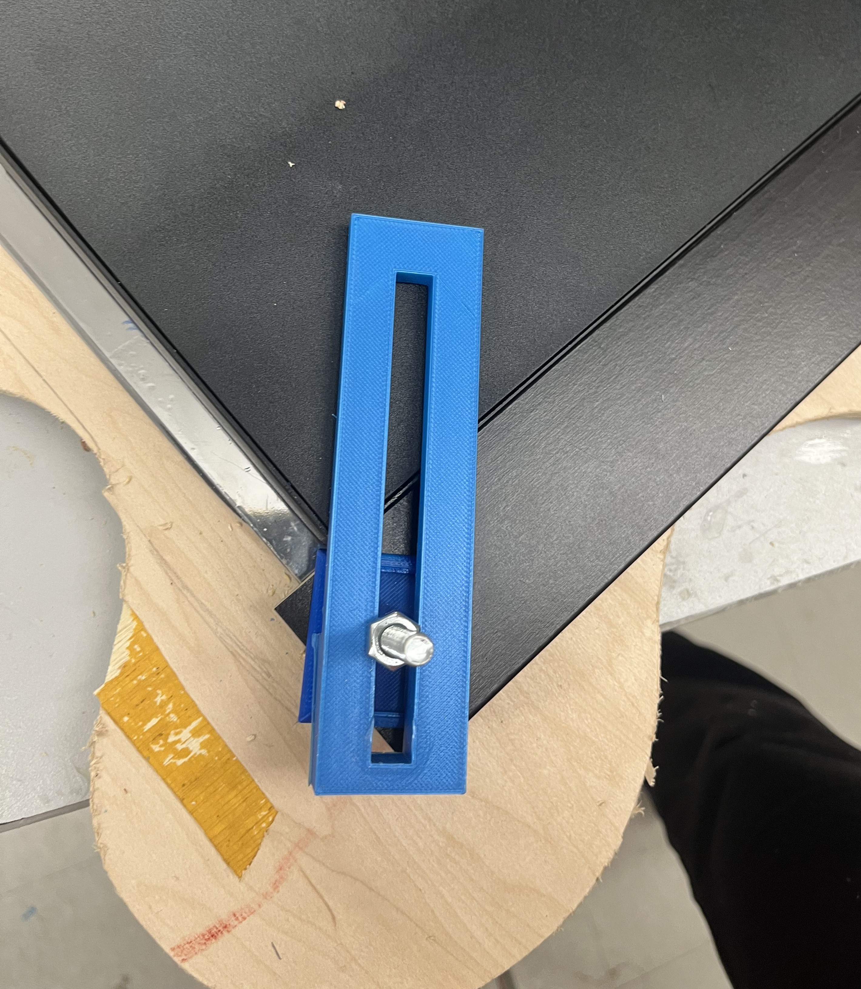
After my clamps were printed I could finally use them!!
Here is what my final 3D printed clamps looked like.
Final 3D Printed Clamps
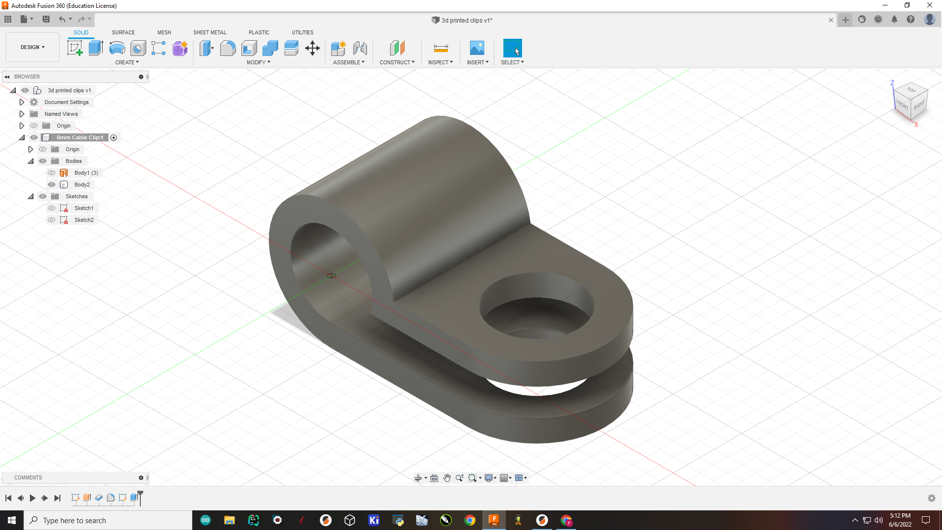
3d Printed Clips
To make these clips, I followed this Kevin Kennedy tutorial
Here is where you can find it:
This was my fusion file:
1 . I first createed a sketch.
2 . Then, I extruded the sketch.
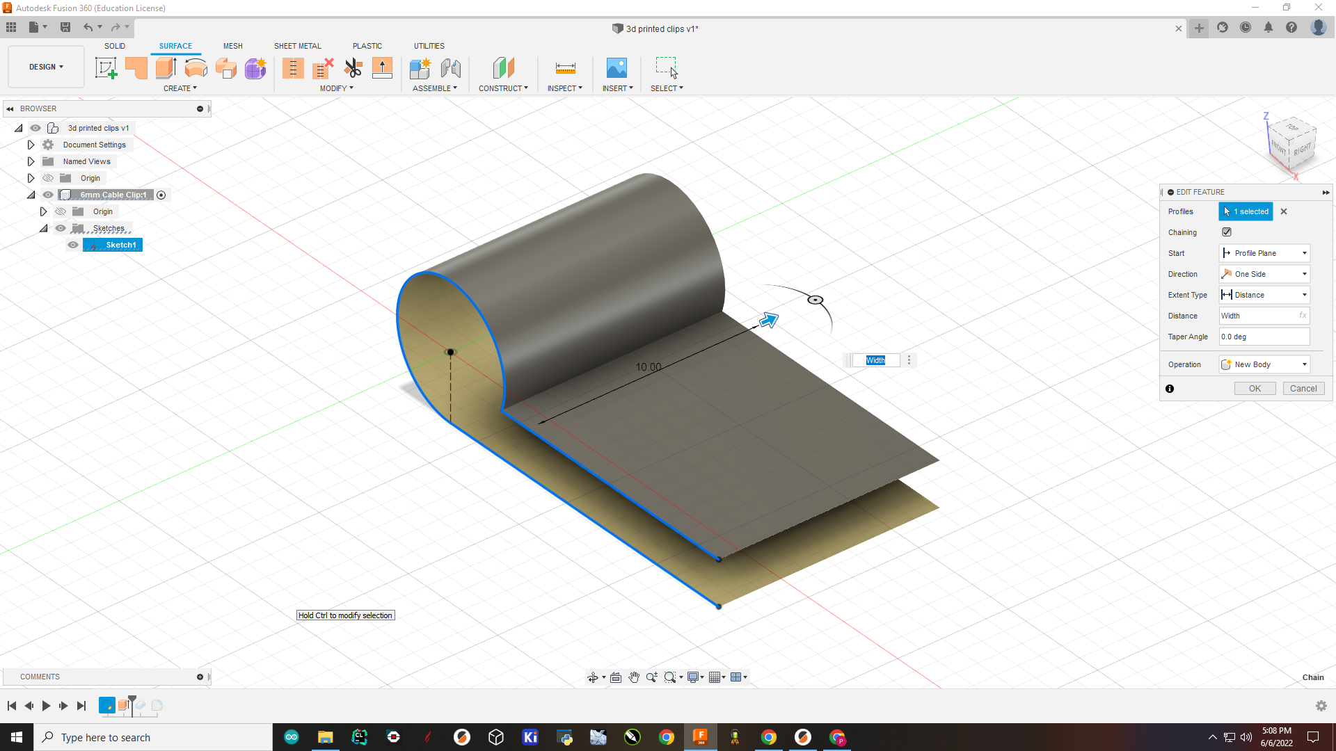
3 . I then thickened the clip
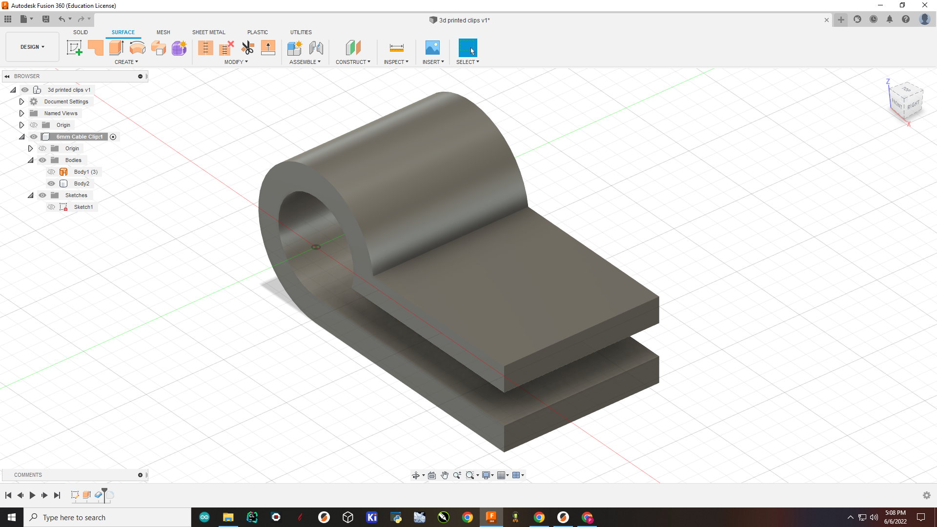
4 . Then filleted the edges
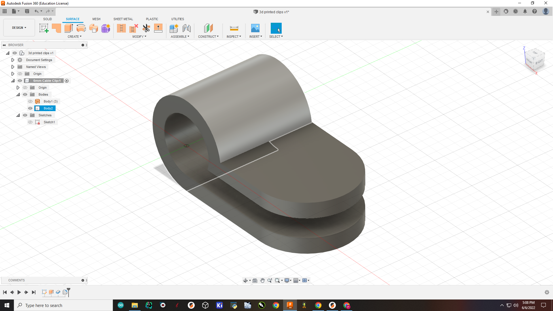
5 . Making the hole
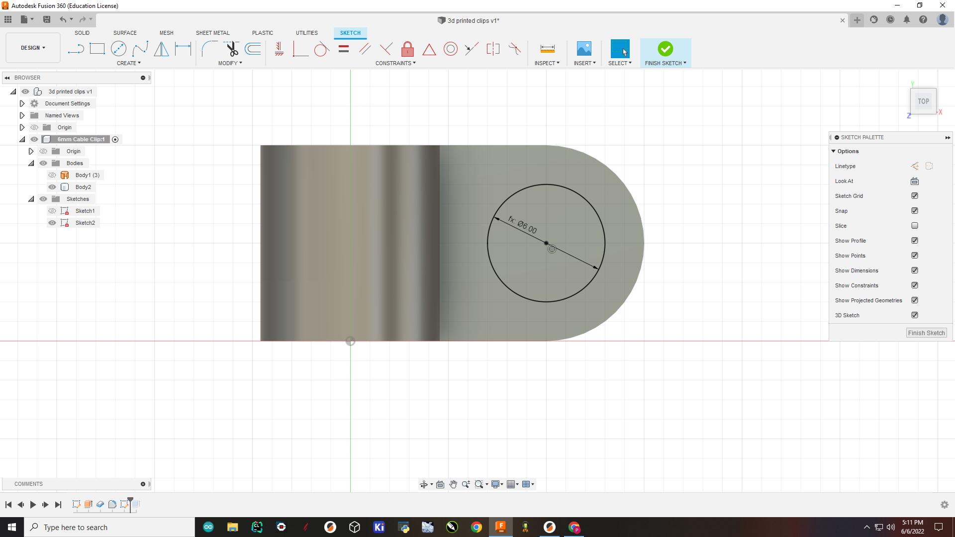
6 . Using extrude feature to make the hole.
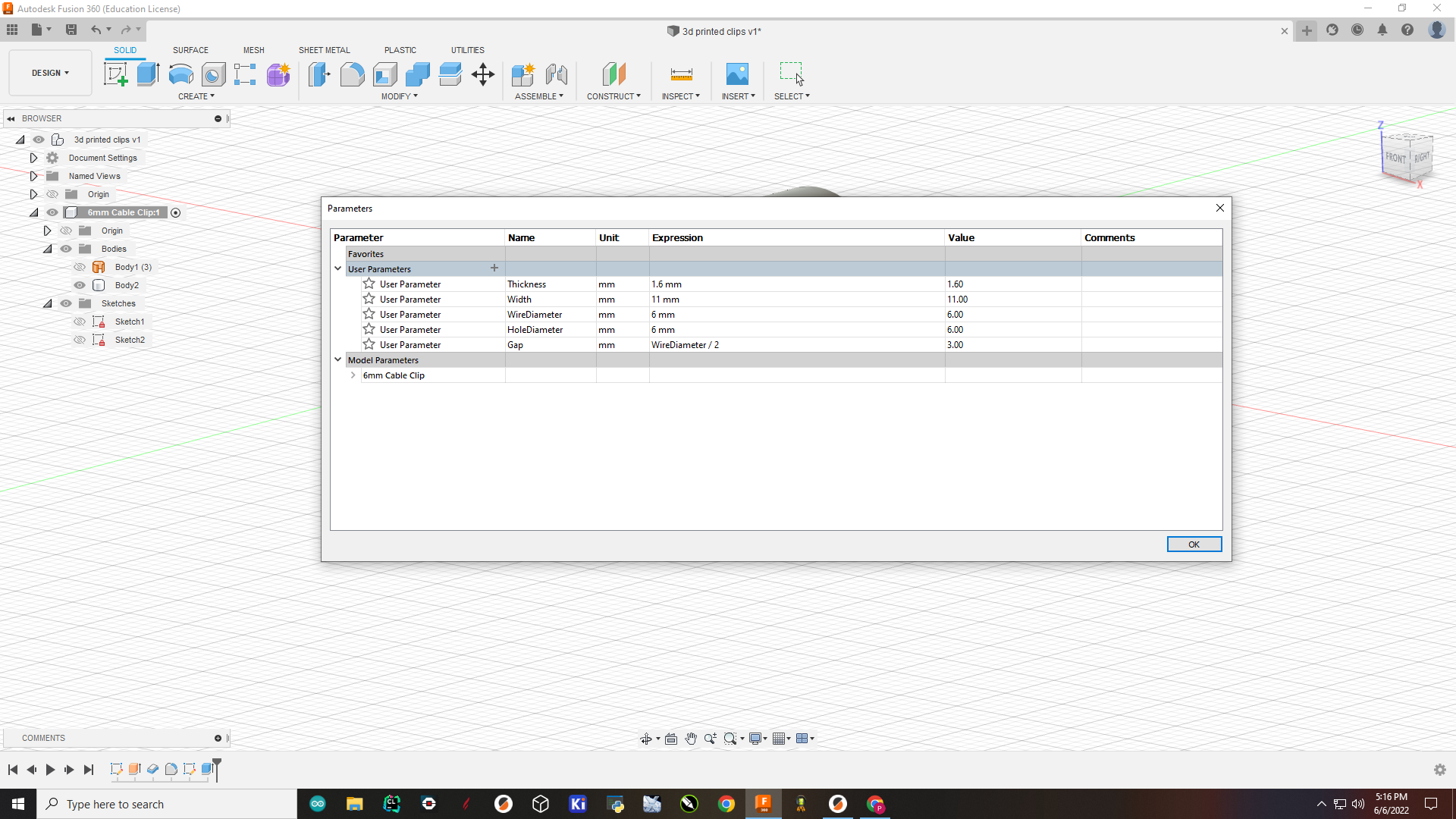
7 . These were the parameters I used.
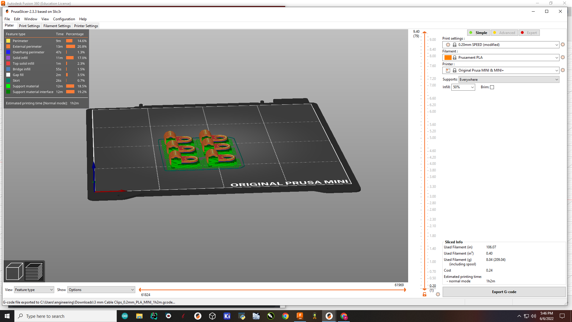
I then used my week 6documentation to 3d print my clamps.
Here is what it looks like on Prusa Slicer
Raspberry Pi and Magic Mirror API
For my final project, the main function was the Magic Mirror API/Software. Magic Mirror is open-source software, which allows anyone to download and use it. To add to this software to make it better, people can make 3rd Party modules. This is something I did. You can see more information on that below and during my documentation for Week 16
Here is where you can find the open source website for Magic Mirror. Most of the instructions on how to install it are on this page of the website.
I followed these directions to install the API. I personally also like o watch videos to help me. I found a very helpful video that walks you step-by-step on how to download this installation.
Here is the Youtube video I used:
I highly recommend this video, it is SUPER helpful.
Once followed this video I successfully installed the Magic mirror API.
Here are some pictures of the process:
1 . Download and install the latest Node.js version:
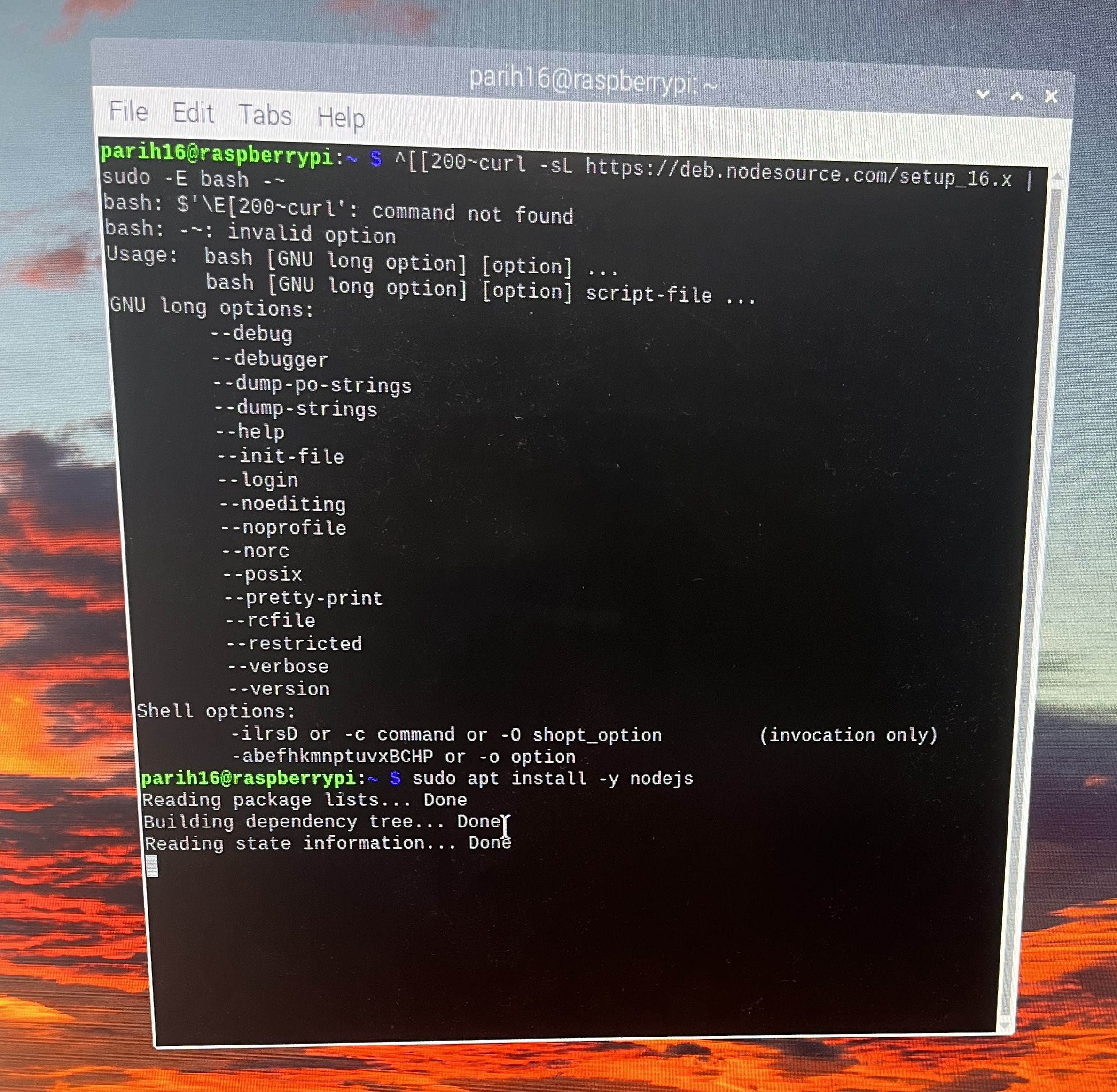
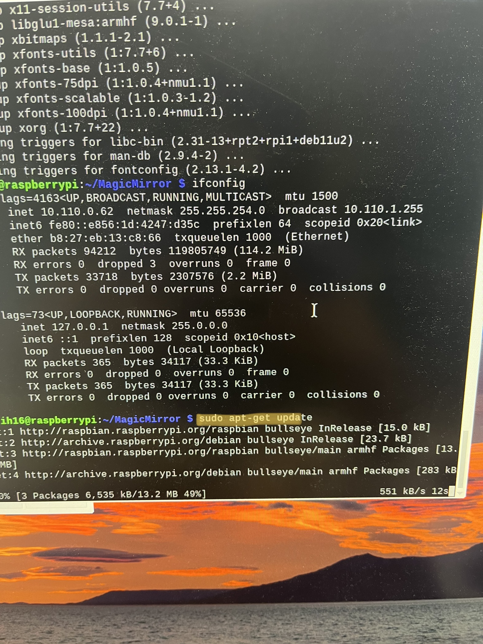
2 . Installed any updates for Node.js
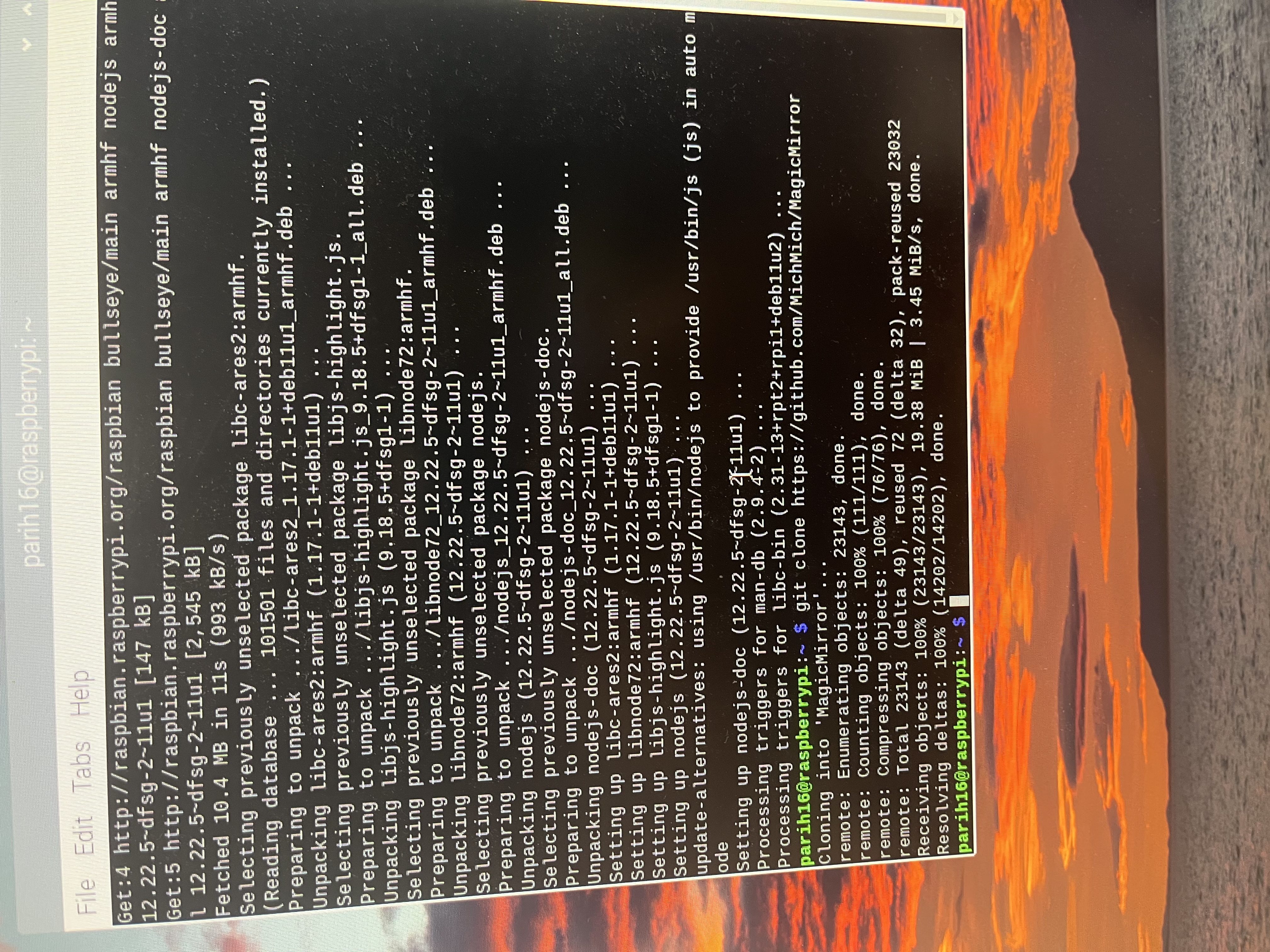
3 . Clone the repository
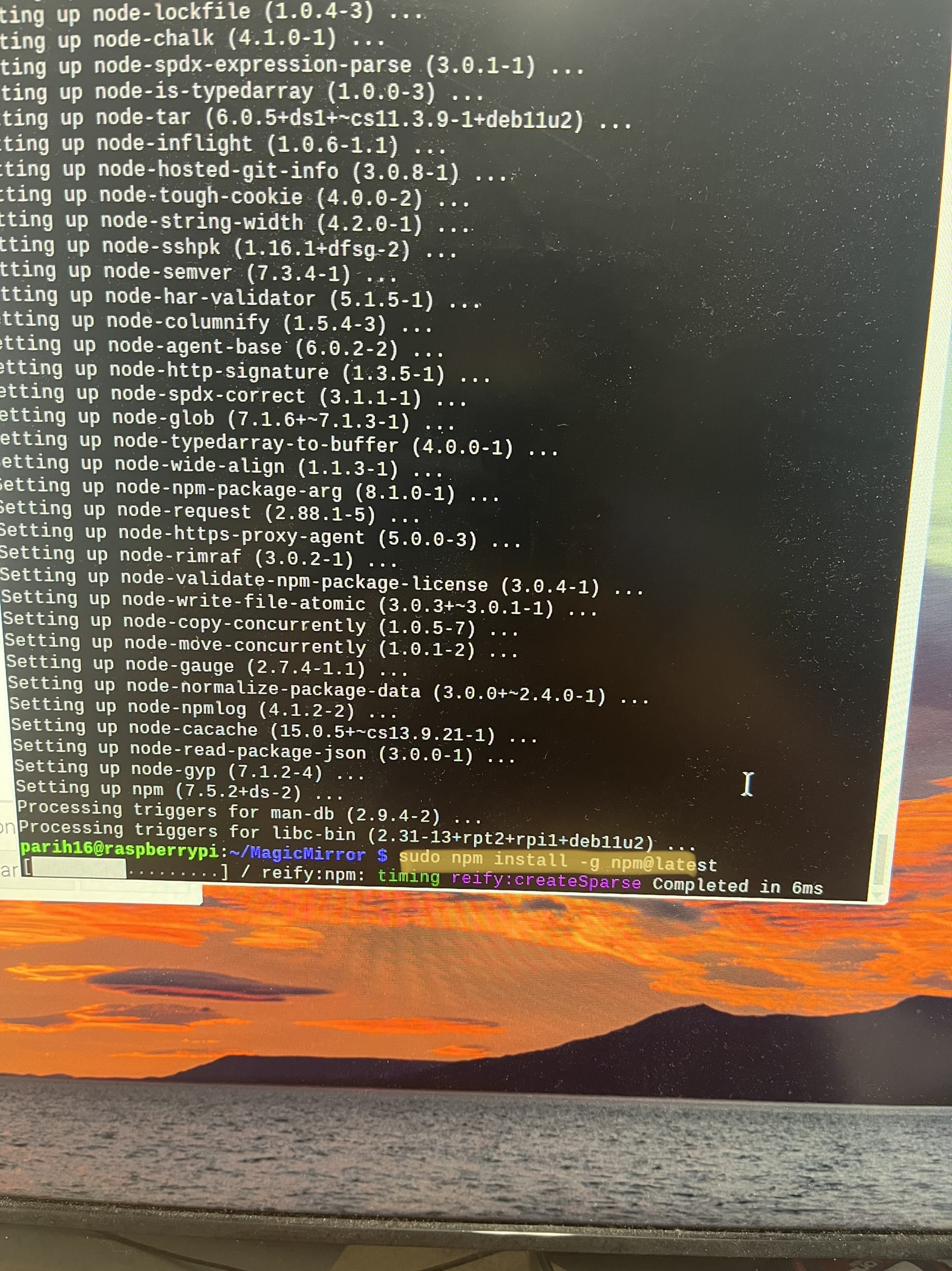
4 . Install the application
Now you are all done installing the application!
How to auto-start the application
Instead of downloading everything all over again, I also downloaded an autostarting system using PM2.
PM2 is a production process manager for Node.js applications with a built-in load balancer. It allows you to keep applications alive forever, reload them without downtime, and facilitate common system admin tasks.
With that being said, I started to download PM2.
I followed this link to download PM2 I recommend that you use it.
To start the mirror go into the terminal and enter this line of code:
This will start the mirror, as shown:
To end the application enter this line of code:
Electronics
Neopixel and Doppler Radar
To bring this section of the project, I first looked at my Week 11 documentation. My goal was to get the doppler radar to send a signal to the Raspberry pi, and at the same time, the doppler radar has to send a message to turn on/off the Neopixels. To do this I first drew out a diagram to figure out how this will work. I decided to use my Input board, which I used during Week 11 as a starting point. This helped me firmly understand the overall concept of my electronics.
My electronics seem simple when talking about them although, they aren’t.
Electronics:
Doppler —> Neopixels
Humidity sensor—> FTDI —> RX/TX Commmunication with Raspberry Pi.
I first started by programming the neopixels.
AT first, they didn’t work, although I then went to strand the strand test and that seemed to work, although when going on doppler code it didn’t work we tried all the boards but the strand test worked. the doppler is not working. for output week I also have the wrong code. so went to strand test, just to test if my neopixels were working.
They did, although I have found that the AtTiny 412 chips don’t work with the example called “simple”.
Here is the code for strand test:
#include <tinyNeoPixel_Static.h>

#define PIN 1

// Parameter 1 = number of pixels in strip
// Parameter 2 = Arduino pin number (most are valid)
// Parameter 3 = pixel type flags, add together as needed:
//   NEO_GRB     Pixels are wired for GRB bitstream (most NeoPixel products)
//   NEO_RGB     Pixels are wired for RGB bitstream (v1 FLORA pixels, not v2)
// Parameter 4 = array to store pixel data in

#define NUMPIXELS 5

// Since this is for the static version of the library, we need to supply the pixel array
// This saves space by eliminating use of malloc() and free(), and makes the RAM used for
// the frame buffer show up when the sketch is compiled.

byte pixels[NUMPIXELS * 3];

// When we setup the NeoPixel library, we tell it how many pixels, and which pin to use to send signals.
// Note that for older NeoPixel strips you might need to change the third parameter--see the strandtest
// example for more information on possible values. Finally, for the 4th argument we pass the array we
// defined above.

tinyNeoPixel strip = tinyNeoPixel(NUMPIXELS, PIN, NEO_GRB, pixels);

// IMPORTANT: To reduce NeoPixel burnout risk, add 1000 uF capacitor across
// pixel power leads, add 300 - 500 Ohm resistor on first pixel's data input
// and minimize distance between Arduino and first pixel.  Avoid connecting
// on a live circuit...if you must, connect GND first.

void setup() {
  pinMode(PIN, OUTPUT); // set pin output - this is not done internally by the library for Static version of library
  // strip.begin(); // Static version does not use this.
  strip.show(); // Initialize all pixels to 'off'
}

void loop() {
  // Some example procedures showing how to display to the pixels:
  colorWipe(strip.Color(255, 0, 0), 50); // Red
  colorWipe(strip.Color(0, 255, 0), 50); // Green
  colorWipe(strip.Color(0, 0, 255), 50); // Blue
  // Send a theater pixel chase in...
  theaterChase(strip.Color(127, 127, 127), 50); // White
  theaterChase(strip.Color(127, 0, 0), 50); // Red
  theaterChase(strip.Color(0, 0, 127), 50); // Blue

  rainbow(20);
  rainbowCycle(20);
  theaterChaseRainbow(50);
}

// Fill the dots one after the other with a color
void colorWipe(uint32_t c, uint8_t wait) {
  for (uint16_t i = 0; i < strip.numPixels(); i++) {
    strip.setPixelColor(i, c);
    strip.show();
    delay(wait);
  }
}

void rainbow(uint8_t wait) {
  uint16_t i, j;

  for (j = 0; j < 256; j++) {
    for (i = 0; i < strip.numPixels(); i++) {
      strip.setPixelColor(i, Wheel((i + j) & 255));
    }
    strip.show();
    delay(wait);
  }
}

// Slightly different, this makes the rainbow equally distributed throughout
void rainbowCycle(uint8_t wait) {
  uint16_t i, j;

  for (j = 0; j < 256 * 5; j++) { // 5 cycles of all colors on wheel
    for (i = 0; i < strip.numPixels(); i++) {
      strip.setPixelColor(i, Wheel(((i * 256 / strip.numPixels()) + j) & 255));
    }
    strip.show();
    delay(wait);
  }
}

// Theatre-style crawling lights.
void theaterChase(uint32_t c, uint8_t wait) {
  for (int j = 0; j < 10; j++) { // do 10 cycles of chasing
    for (int q = 0; q < 3; q++) {
      for (uint16_t i = 0; i < strip.numPixels(); i = i + 3) {
        strip.setPixelColor(i + q, c);  // turn every third pixel on
      }
      strip.show();

      delay(wait);

      for (uint16_t i = 0; i < strip.numPixels(); i = i + 3) {
        strip.setPixelColor(i + q, 0);      // turn every third pixel off
      }
    }
  }
}

// Theatre-style crawling lights with rainbow effect
void theaterChaseRainbow(uint8_t wait) {
  for (int j = 0; j < 256; j++) {   // cycle all 256 colors in the wheel
    for (int q = 0; q < 3; q++) {
      for (uint16_t i = 0; i < strip.numPixels(); i = i + 3) {
        strip.setPixelColor(i + q, Wheel((i + j) % 255)); // turn every third pixel on
      }
      strip.show();

      delay(wait);

      for (uint16_t i = 0; i < strip.numPixels(); i = i + 3) {
        strip.setPixelColor(i + q, 0);      // turn every third pixel off
      }
    }
  }
}

// Input a value 0 to 255 to get a color value.
// The colours are a transition r - g - b - back to r.
uint32_t Wheel(byte WheelPos) {
  WheelPos = 255 - WheelPos;
  if (WheelPos < 85) {
    return strip.Color(255 - WheelPos * 3, 0, WheelPos * 3);
  }
  if (WheelPos < 170) {
    WheelPos -= 85;
    return strip.Color(0, WheelPos * 3, 255 - WheelPos * 3);
  }
  WheelPos -= 170;
  return strip.Color(WheelPos * 3, 255 - WheelPos * 3, 0);
}
When this worked, I wrote custom code for the doppler to turn on/ off the neopixels. This was the code:
#include <tinyNeoPixel_Static.h>
#define PIN 1 //check
#define NUMPIXELS 3
#define Sensor 5

byte pixels[NUMPIXELS * 3];

tinyNeoPixel strip = tinyNeoPixel(NUMPIXELS, PIN, NEO_GRB, pixels);

int delayval = 500; // delay for half a second

void setup(){
  pinMode(PIN, OUTPUT); // set pin output - this is not done internally by the library for Static version of library
strip.show(); // Initialize all pixels to 'off'

  Serial.swap(1);
  Serial.begin(9600);
}

void loop(){

//bool Detection= digitalRead(Sensor);

if(digitalRead(Sensor) == HIGH){

Serial.println("A");  //This sends the character 'A' to the Pi which means it detected motion

//Add your code to turn ON the Neopixel here
 colorWipe(strip.Color(255, 0, 0), 50); // Red
}
else{// do u need a if statement
  Serial.println ("B");
  colorWipe(strip.Color(255, 255, 255), 50); // white
}

}
void colorWipe(uint32_t c, uint8_t wait) {
 for (uint16_t i = 0; i < strip.numPixels(); i++) {
 strip.setPixelColor(i, c);
 strip.show();
 delay(wait);

 }
}
Schematic for Doppler Radar and Neopixels
![]()
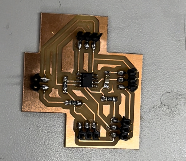
PCB for Doppler Radar and Neopixels
![]()
I followed my documentation for milling the board. You can refer to my Week 7 to get more details.
I then Sodered my board. To see the process check out this video:
Sodered board
After doing all of this, I uploaded the Code above, to the ATtiny 412 chip, and recivbed my results. To upload my code I followedthe steps from Week 11.
After uploading the code, The doppler and neopixel finally worked!!!
For my Raspberry Pi to read the Values of the Doppler, I wrote this python script/code which I ran in the back. This code read the Values from the doppler and controlled the power on/off of the screen.
Code for Raspberry Pi to Read Doppler Signals
#!/usr/bin/env python3
import humidityImage
import serial
from gpiozero import MotionSensor
from subprocess import call
from time import sleep

if __name__ == '__main__':
ser = serial.Serial('/dev/ttyUSB0', 9600, timeout=1)
ser.reset_input_buffer()
while True:
if ser.in_waiting > 0:  #If there's something on the serial input, then turn the screen on
call(['vcgencmd', 'display_power', '1']) #turn HDMI monitor on
humidityImage.readHumidity()
ser.reset_input_buffer()
sleep(800) #sleep for 300 seconds (5 minutes) then turn screen off again:
call(['vcgencmd', 'display_power', '0']) #turn HDMI monitor off
sleep(800)
Working Motion Sensing Neopixels with Doppler Radar
Humidity Sensor
Most of the work for this section I had done during Week 16, and it is all documented. I used that work towards my final project.
To see more details visit my Week 16 page.
Here is the code for my humidity sensor:
#include "DHT.h"
#define DHTPIN 8    // Digital pin connected to the DHT sensor
#define DHTTYPE DHT11   // DHT 11

DHT dht(DHTPIN, DHTTYPE);

void setup() {
  Serial.begin(9600);
    dht.begin();
}

void loop() {
  //Serial.println("1");
  delay(300);// ask if i need a delay
  float h = dht.readHumidity();
  Serial.println(h);

}

// add 3rd party module
Here is the code I used to create my UI and get current humidity values on my UI.
from PIL import Image, ImageFont, ImageDraw
import Adafruit_DHT
import time
import serial

#inside your I2C/serial code main while loop you created in step 2,  where it continuously prints the humidity, replace the "print()" statement with t
#the following and make sure you put in the humidity variable as whatever your I2C code calls it (I don't have your code for this so I have no idea what you have it named).
def readHumidity():
DHT_SENSOR= Adafruit_DHT.DHT11
DHT_PIN=18 #i2c pin or normal pin on RPI?

#Image Starts here

#Dimensions of Picture
width = 550
height = 200

#Message of Picture
message = "Humidity "

#Font Size and Type
font = ImageFont.truetype("PlayfairDisplay-font.ttf", size=65)

#background of image
img = Image.new('RGB', (width, height), color='black')

imgDraw = ImageDraw.Draw(img)

ser = serial.Serial('/dev/ttyUSB0', 9600, timeout=1)
ser.reset_input_buffer()
#humidity, temperature = Adafruit_DHT.read(DHT_SENSOR, DHT_PIN)

valid_reading = False
while not valid_reading:

humidity = ser.readline() # byte string
print(humidity)
if humidity not in [b'\r',b'\n', b'']:
valid_reading = True
textWidth, textHeight = imgDraw.textsize(str(humidity)[2:], font=font)
xText = (width - textWidth) / 2
yText = (height - textHeight) / 2

#Location of text and color
img = Image.new('RGB', (width, height), color='black')
imgDraw = ImageDraw.Draw(img)
imgDraw.text((xText,yText), message + str(humidity)[2: ], font=font, fill=(255, 255,255))

#The final image
img.save('/home/parih16/MagicMirror/modules/MMM-SimpleLogo/public/logo.png')

#Image Ends Here

else:
if humidity not in [b'\r',b'\n']:
print("Sensor failure. Check wiring.");
time.sleep(3);
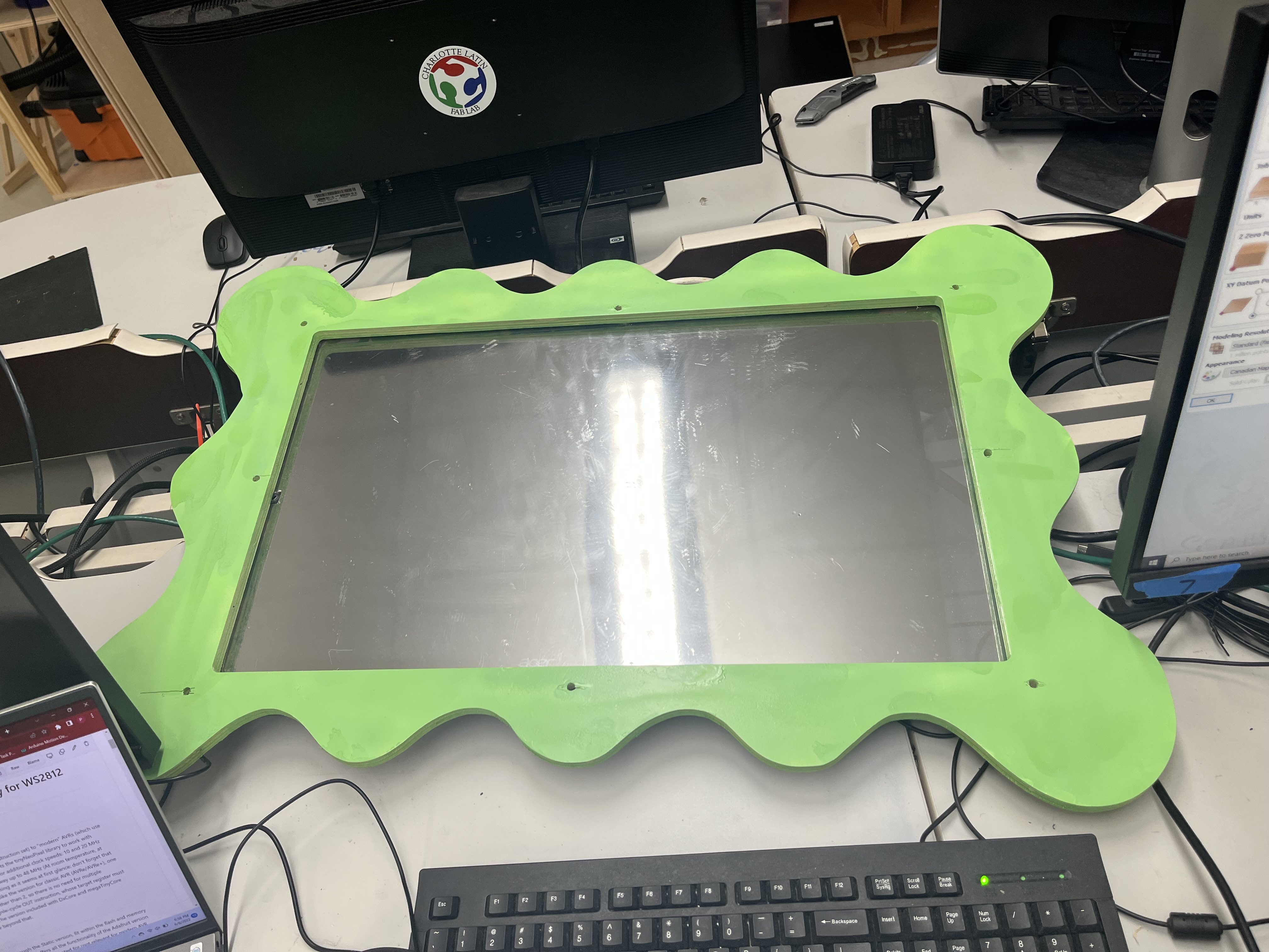
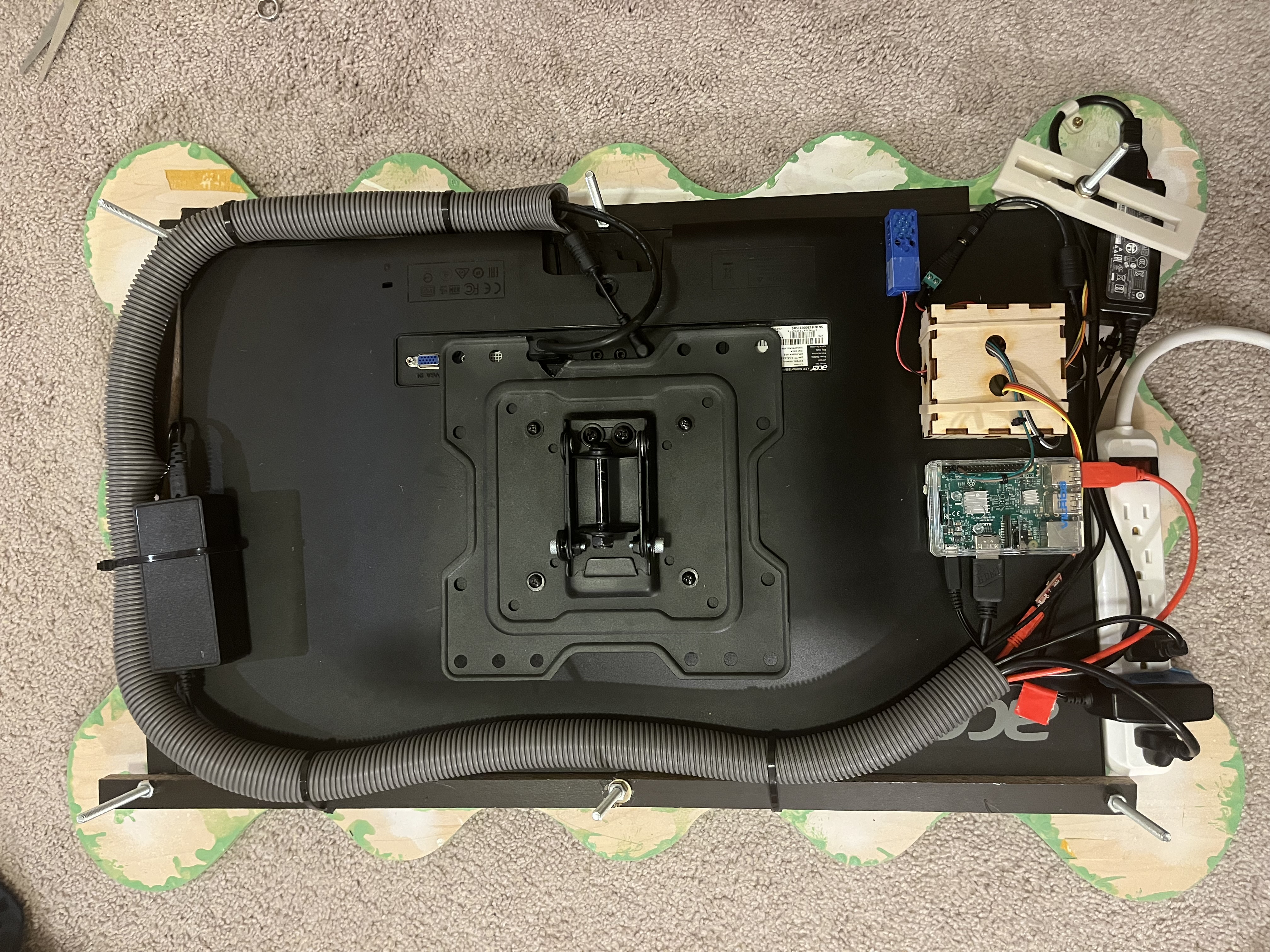
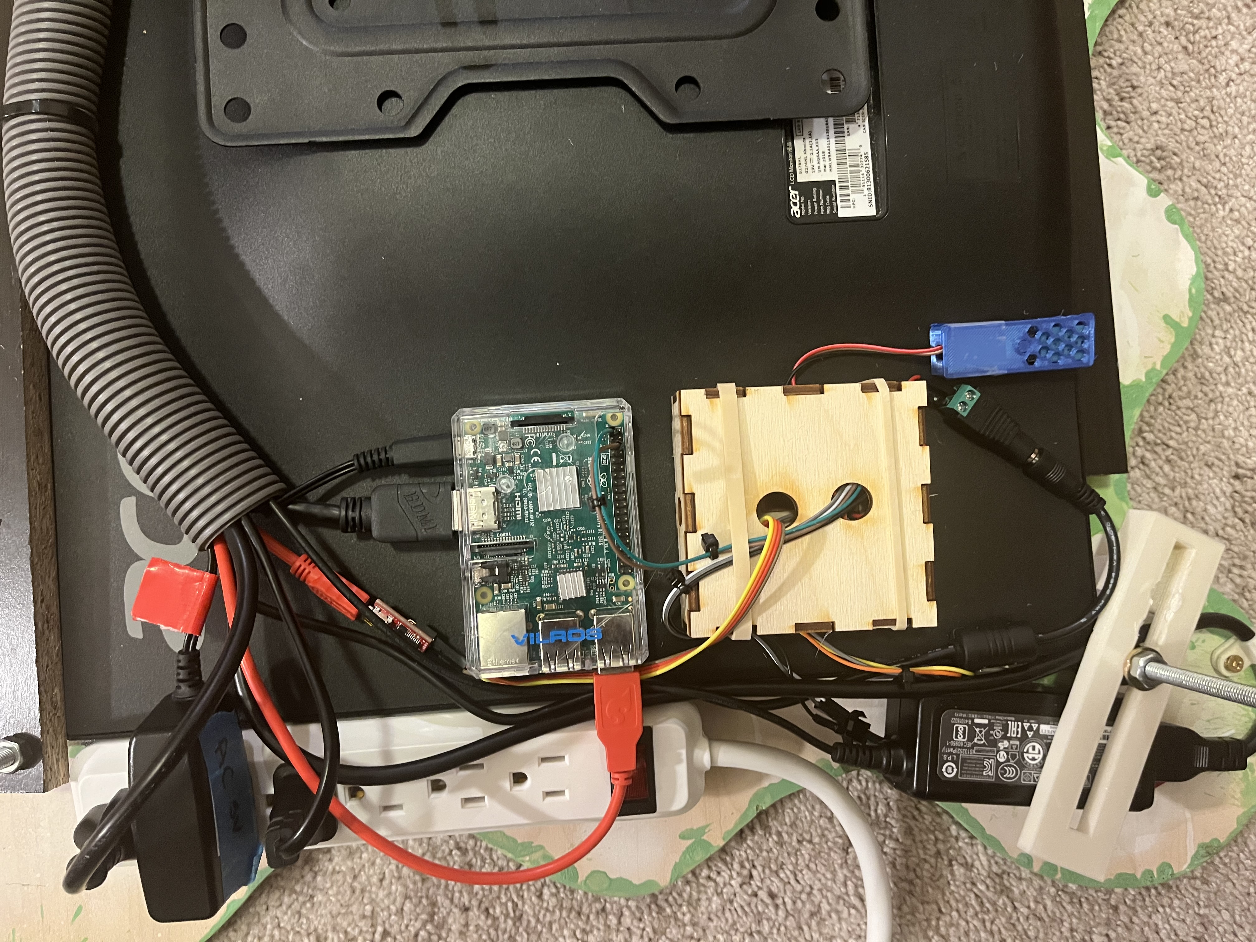
Putting Everything Together
To put everything together I orgnagized everything before using zipties, hot glue, and a wire manager/vaccum tube.
This is what it looked like:
Cutting Wood for backing
Viynl Sticker
Steps to Design Sticker on Corel Draw:
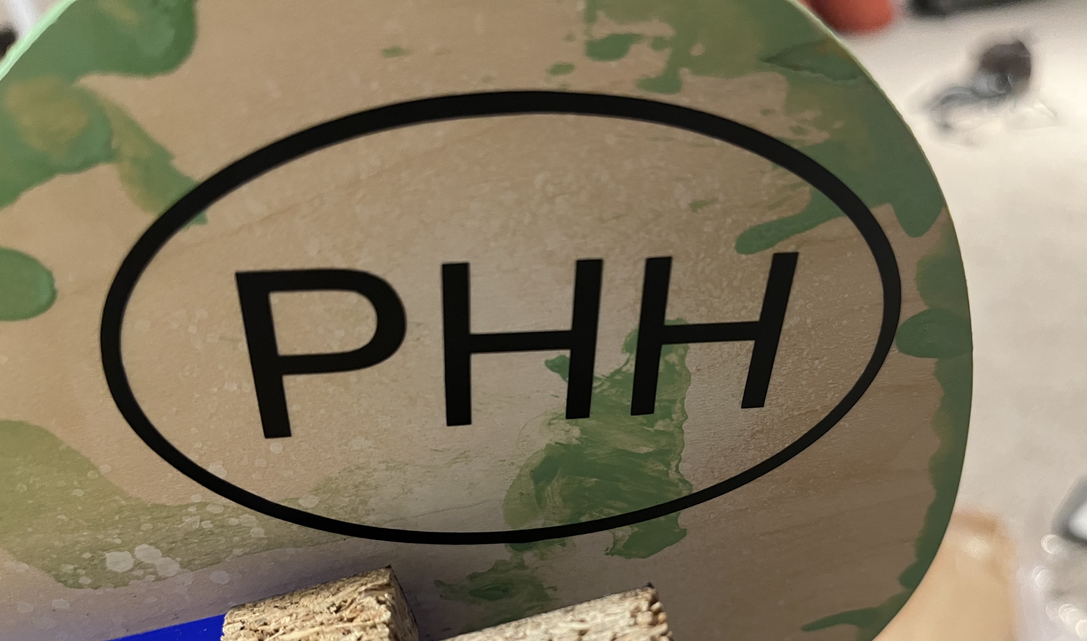
1 . I first drew an ellipse to draw the border and then typed in the letters. I chose my desired font and then turned this image into a path, so the vinyl cutter can process and read the cuts.

2 . This is the path version of the Vinyl sticker.

3 . Then I uploaded my SVG to Corel Draw and followed the Vinyl cutting process, which is attached below.

Using the Viynl Cutter
This process, I very simple although it require close attention. Here’s what to do:
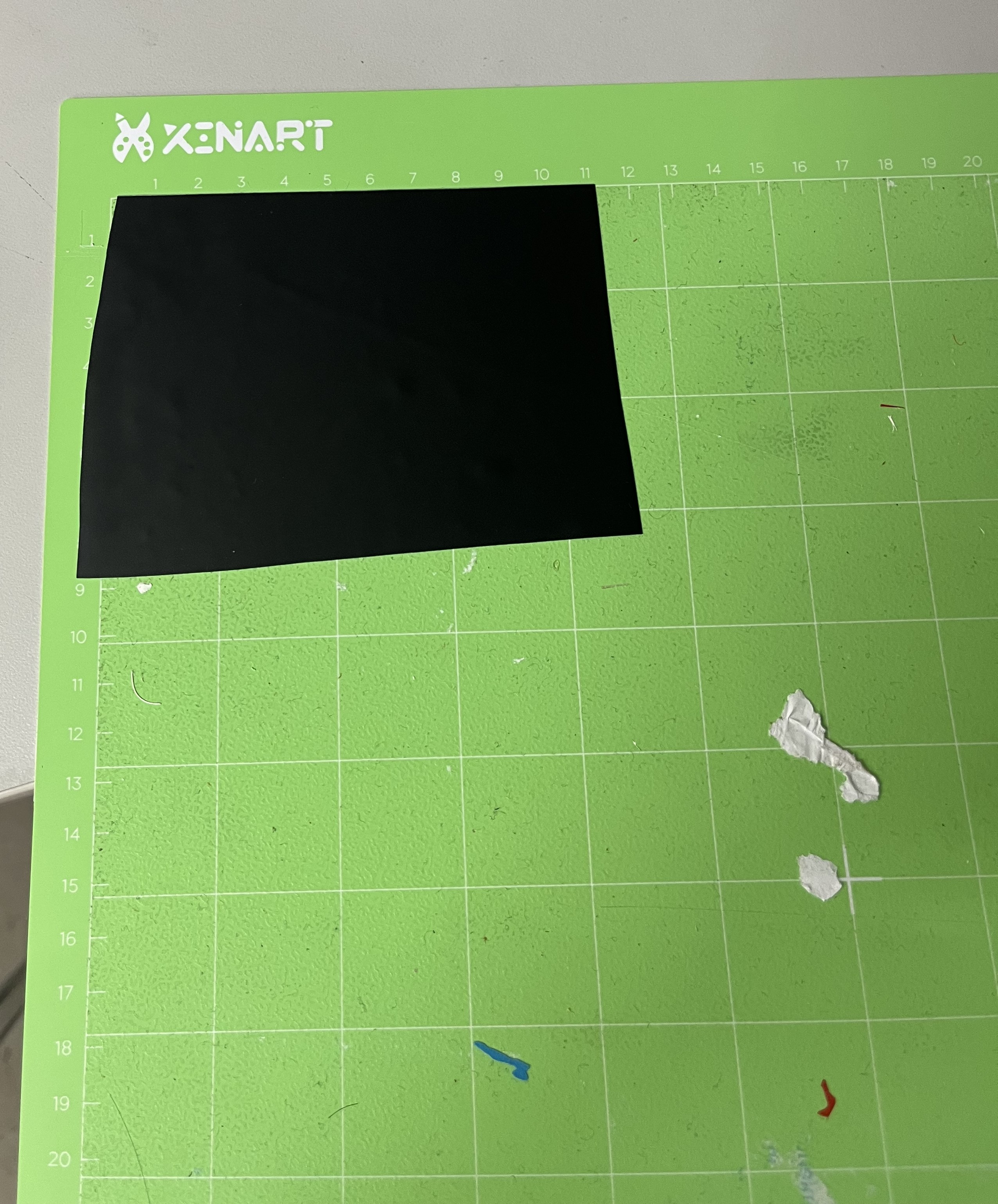
1 . Take a special viynl sticker cutting mat, and cut a peice of viyl the size you want.
2 . Next, load the cutting matt, into the Viynl Cutter, and upload your design into your software. I am using Silhouette Studio.
3 . After making sure everything is secure, click “upload” and print your viynl sticker!
4 . I used tweezers/my hands to weed the vinyl cut.
5 . I then used transfer tape, to finalize my sticker.
6 . Here is my sticker, stuck on my Final Project.
Final Viynl Sticker
Second Viynl Sticker
I also, Viynl cutt a second sticker, for this sticker. For this sticker I followed the same process as above and also dopcumented it during week 4.
Here are some pictures of the process:
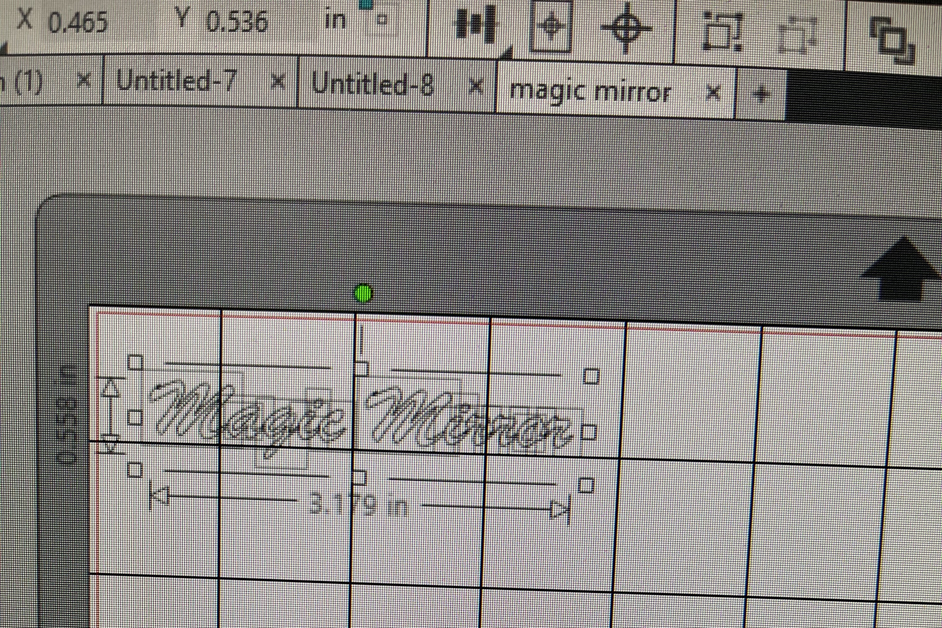
1 . I typed out all the letters “Magic Mirror’. I chose my desired font and then turned this image into a path, so the vinyl cutter can process and read the cuts.
2 . Take a special viynl sticker cutting mat, and cut a peice of viyl the size you want.
3 . Send it to print
4 . I used tweezers/my hands to weed the vinyl cut.
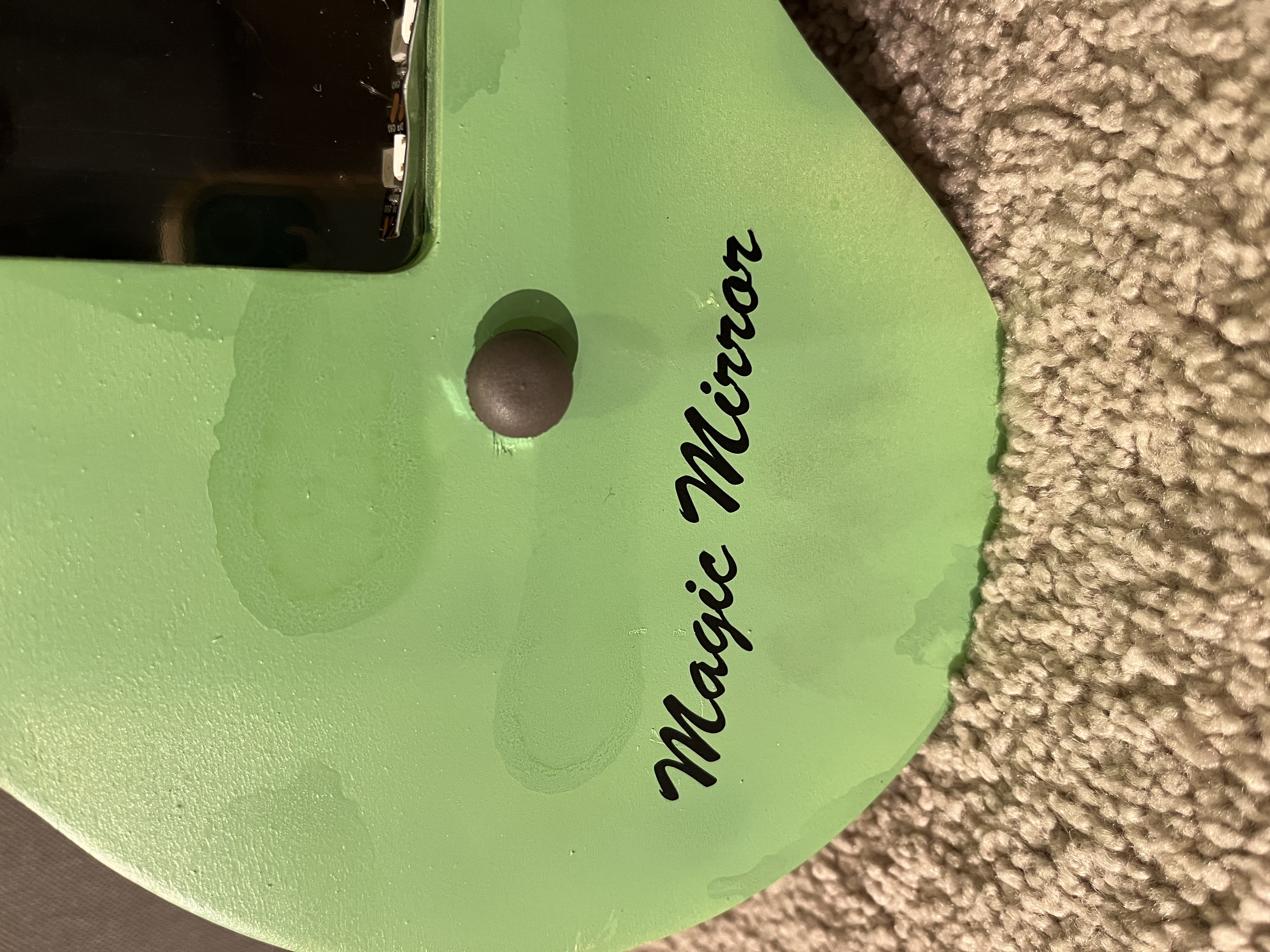
Final Second Viynl Sticker
Final Project
Here are the filesfor my final project.