4. Computer controlled cutting
Assingment: Make a Vinyl Sticker
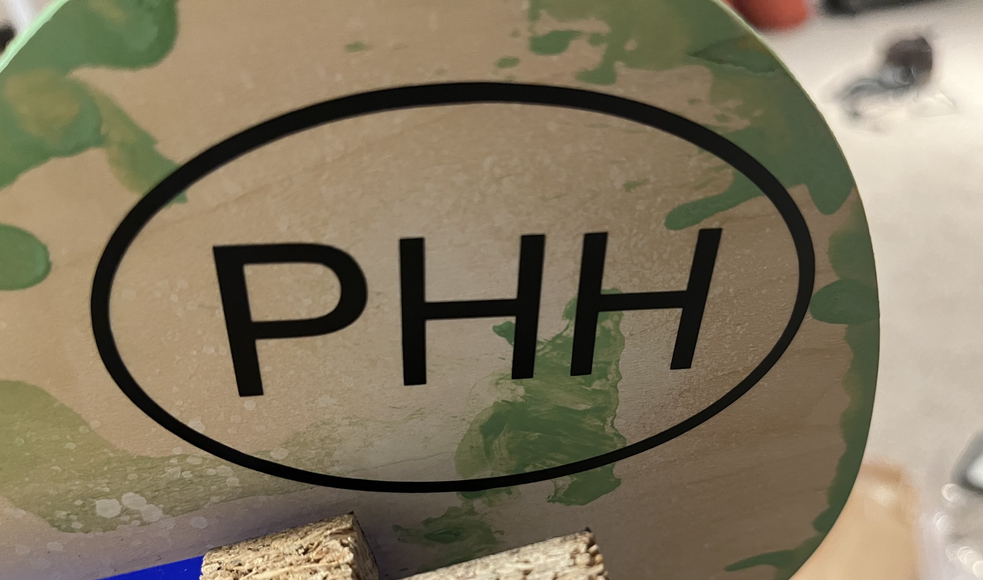
I made a Boba Tea Vinyl Sticker which was a simple process. I referred to a Google Slide which, was used during my Engineering I Principles class during my freshman year of High school. I decided to do something that would contribute onto my final project. So I did my initals “PHH”. Below is the step -by-step process.
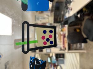
I also decided to do more of a challenging sticker. Boba is one of my favorite drinks, and I also wanted a sticker that could have multiple layers of colors. I used the colors: black, beige, pink, purple, blue, and green. I chose the different colors for the boba because I wanted to give the effect of popping boba. Popping boba is boba that pops in your mouth and releases your chosen flavor. I LOVE this type of boba and decided to incorporate it into my sticker. I have never printed a multilayer vinyl sticker before, and I asked my colleague Aaron Logan and he gave me a simple rundown on how to do it.
These were my files for this week.
Steps to Design Sticker on Corel Draw:
1 . I first drew an ellipse to draw the border and then typed in the letters. I chose my desired font and then turned this image into a path, so the vinyl cutter can process and read the cuts.

2 . This is the path version of the Vinyl sticker.

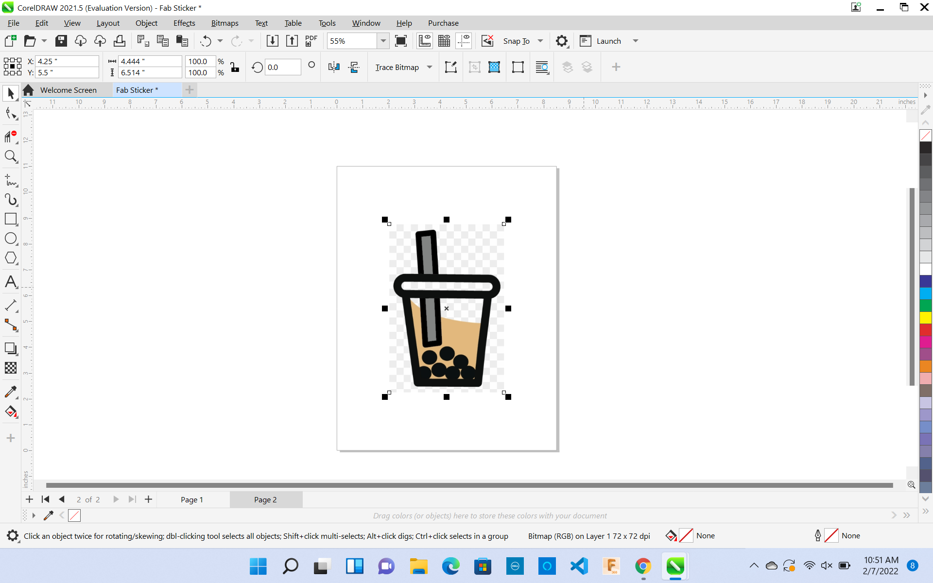
3 . Then I uploaded my SVG to Corel Draw and followed the Vinyl cutting process, which is attached below.

Using the Viynl Cutter
This process, I very simple although it require close attention. Here’s what to do:
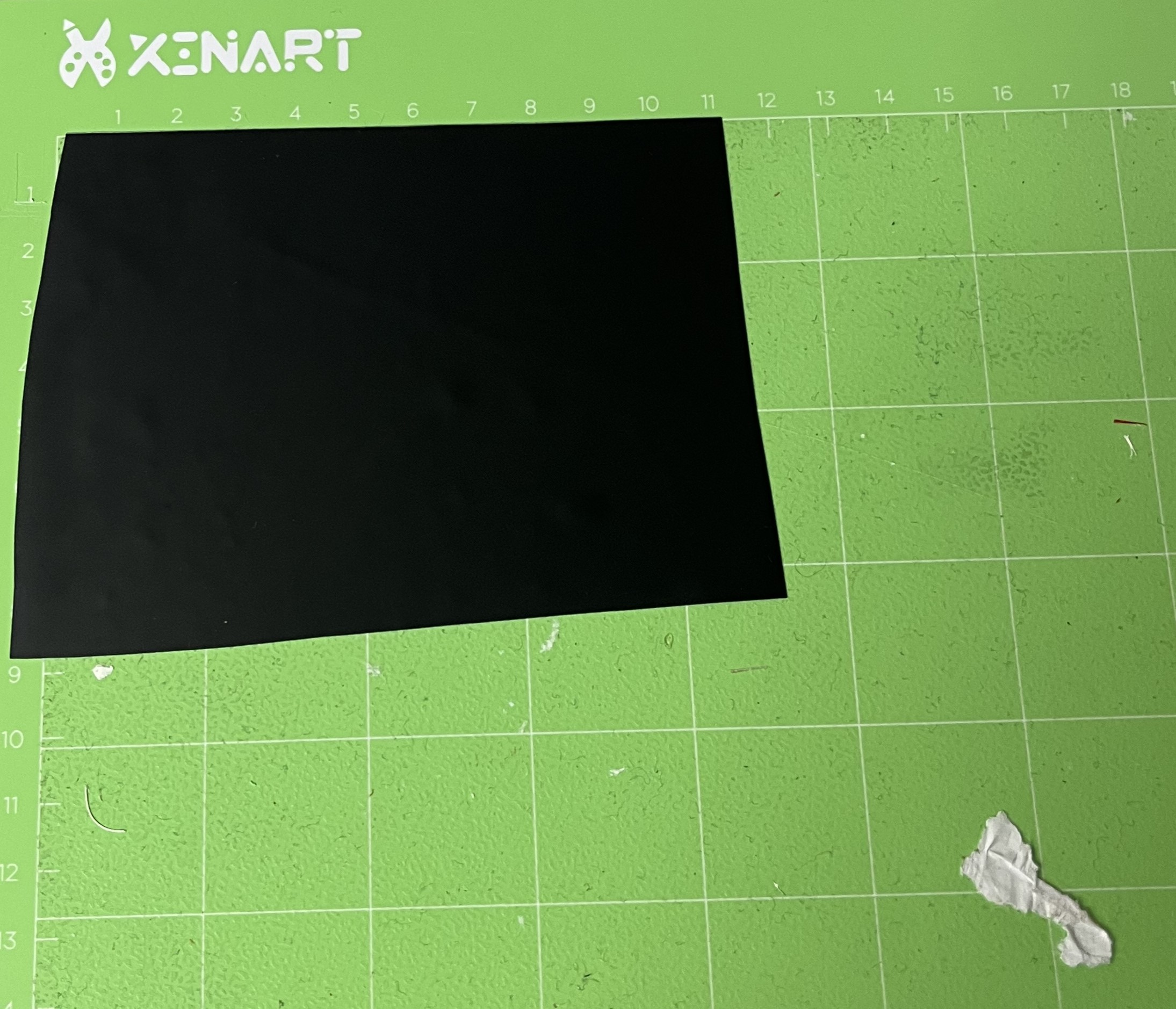
1 . Take a special viynl sticker cutting mat, and cut a peice of viyl the size you want.
2 . Next, load the cutting matt, into the Viynl Cutter, and upload your design into your software. I am using Silhouette Studio.
3 . After making sure everything is secure, click “upload” and print your viynl sticker!
4 . I used tweezers/my hands to weed the vinyl cut.
5 . I then used transfer tape, to finalize my sticker.
6 . Here is my sticker, stuck on my Final Project.
Final Viynl Sticker
Another Sticker
Steps to Design Sticker on Corel Draw:
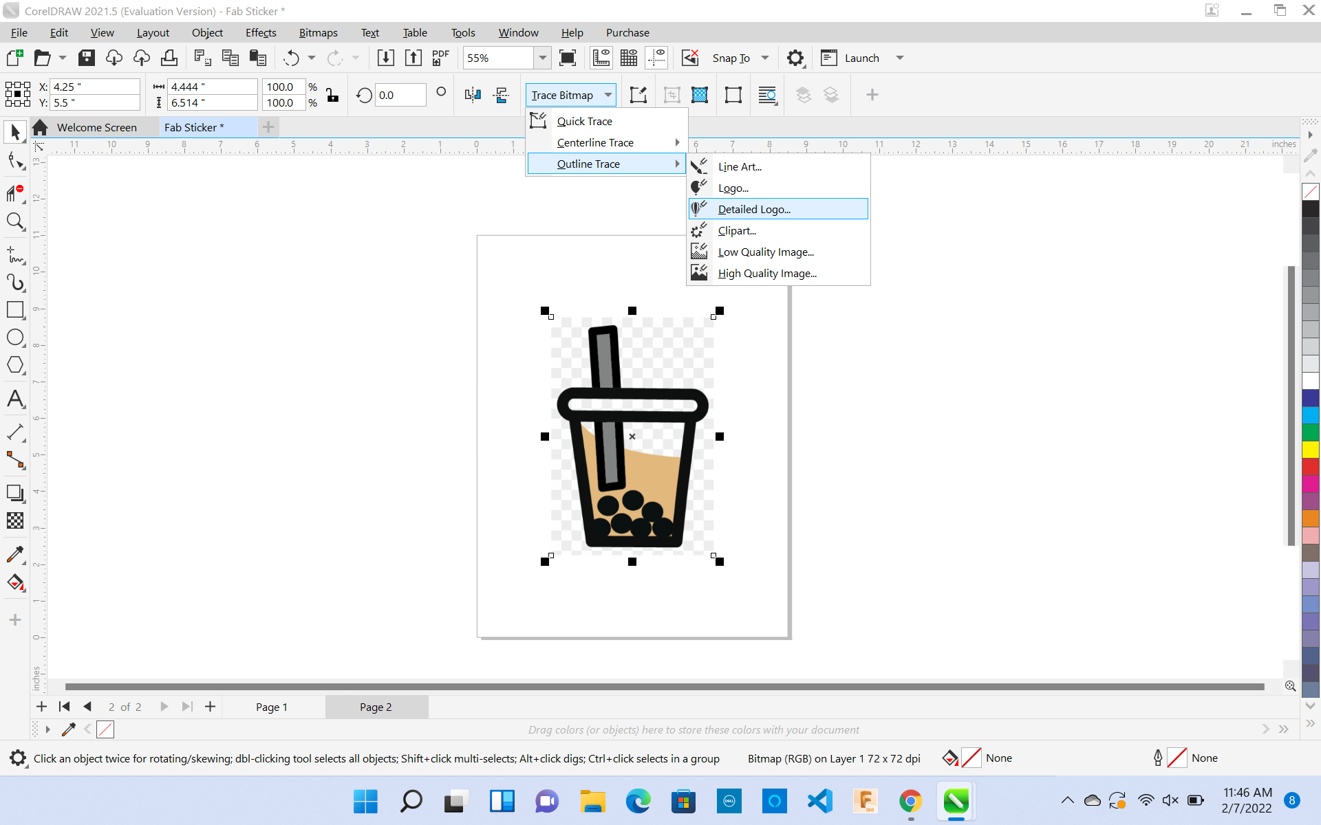
1 . First, find a .png or .jpg online which does not have too many complications and looks simple. Copy/paste this picture into Corel Draw.
2 . Then select Bitmaps > Outline Trace > Detailed Logo. Adjust the Trace Controls to how you would like your design to look.
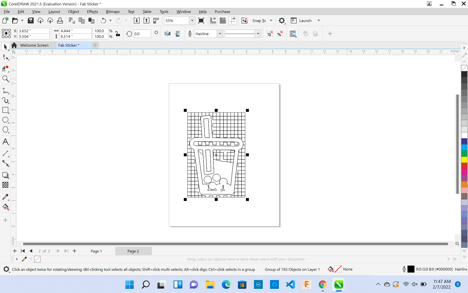
3 . Next, select your entire object and change the Object Properties in the Outline section to thickness the of “Hairline.” During this process, also change the Object Properties Fill Section to “No Fill.” Although during this process, the background of my picture had squares from the clip art. I had to use the virtual segment delete tool to delete all the unwanted paths. This process was quick, although inconvenient.
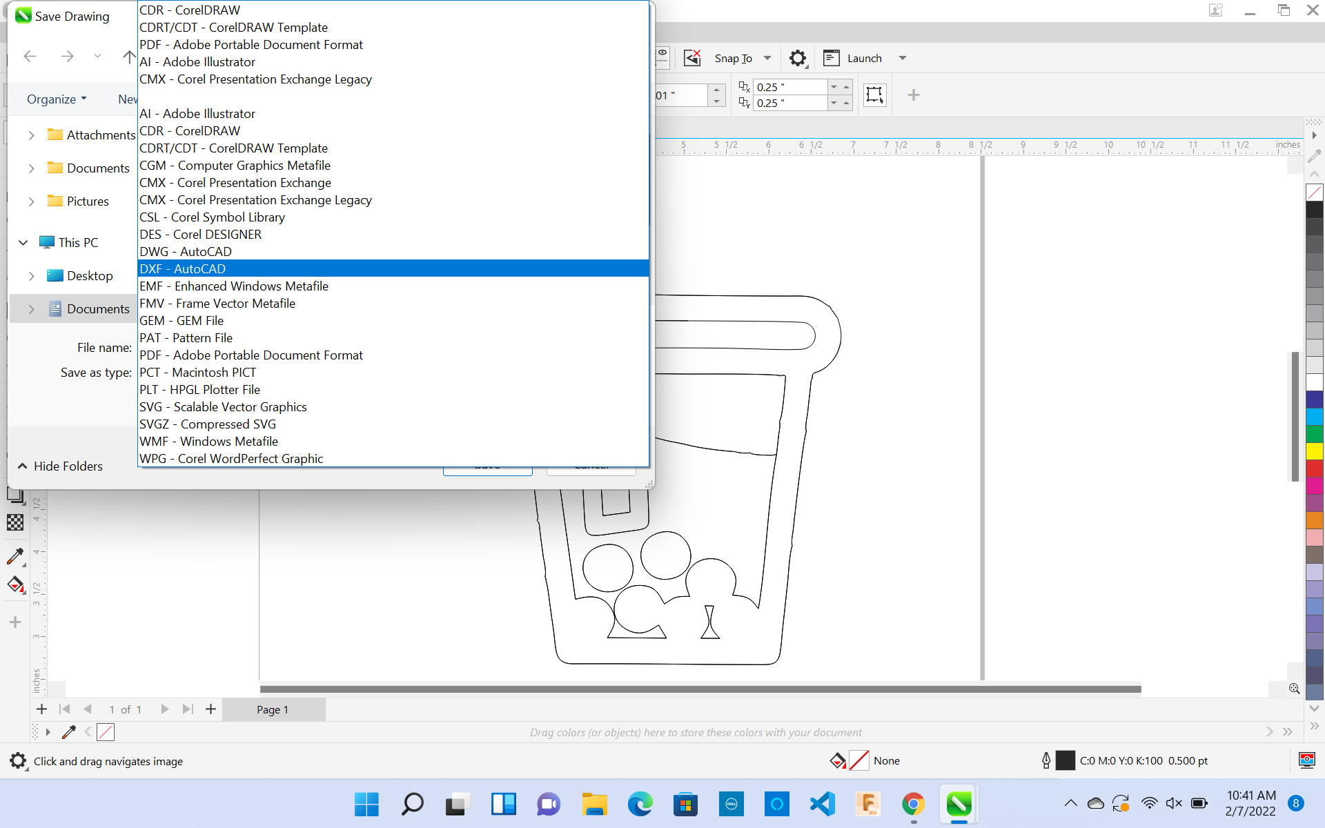
4 . The designing process is now done!! Make sure to save this document as a . DXF and file it in an easily accessed folder.
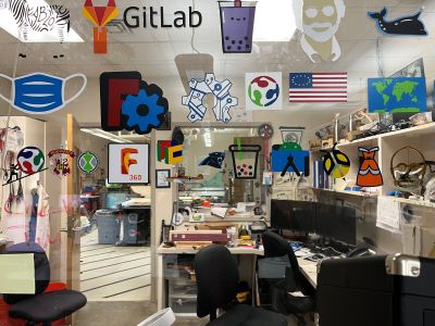
The Charlotte Latin Fab Lab we have a tradition of putting out viynl sticker for Fab academy on the Window for display with all the other Fab Academy students who have taken the cource. I felt very honored and proud that my sticker now also belongs to the wall along with the other sticjers that my collegues made.
Assignment: Make a Parametric Design Kit
This week our assignment was to make a parametric design kit. At first, I was very confused as I did not know what was expected of my final product. I decided to do some research and followed a tutorial by Prusa Printers called Parametric Modeling in Fusion 360, which was recommended by [Tom Dubick] (http://archive.fabacademy.org/fabacademy2016/charlottelatin/students/999/index.html) to give me an overview of what a parametric design is.
After viewing this video, I understood most of the basics of parametric design and tried to start sketching my design using Fusion 360. I had a rough start at first because I wasn’t sure what to design or how to start. Some of my classmates breezed through this assignment, while I was having a hard time figuring out how to make the tabs for the slots in the design. This was a tedious process, as I tried various things such as extruding, cutting, and mirroring. Due to the great difficulty I encountered, I decided to look up another tutorial but I could not find any helpful ones.
After spending almost a whole day on this, I finally got it!!
Steps on How to Create a Parametric Design
Here is the process I used to create my parametric design:
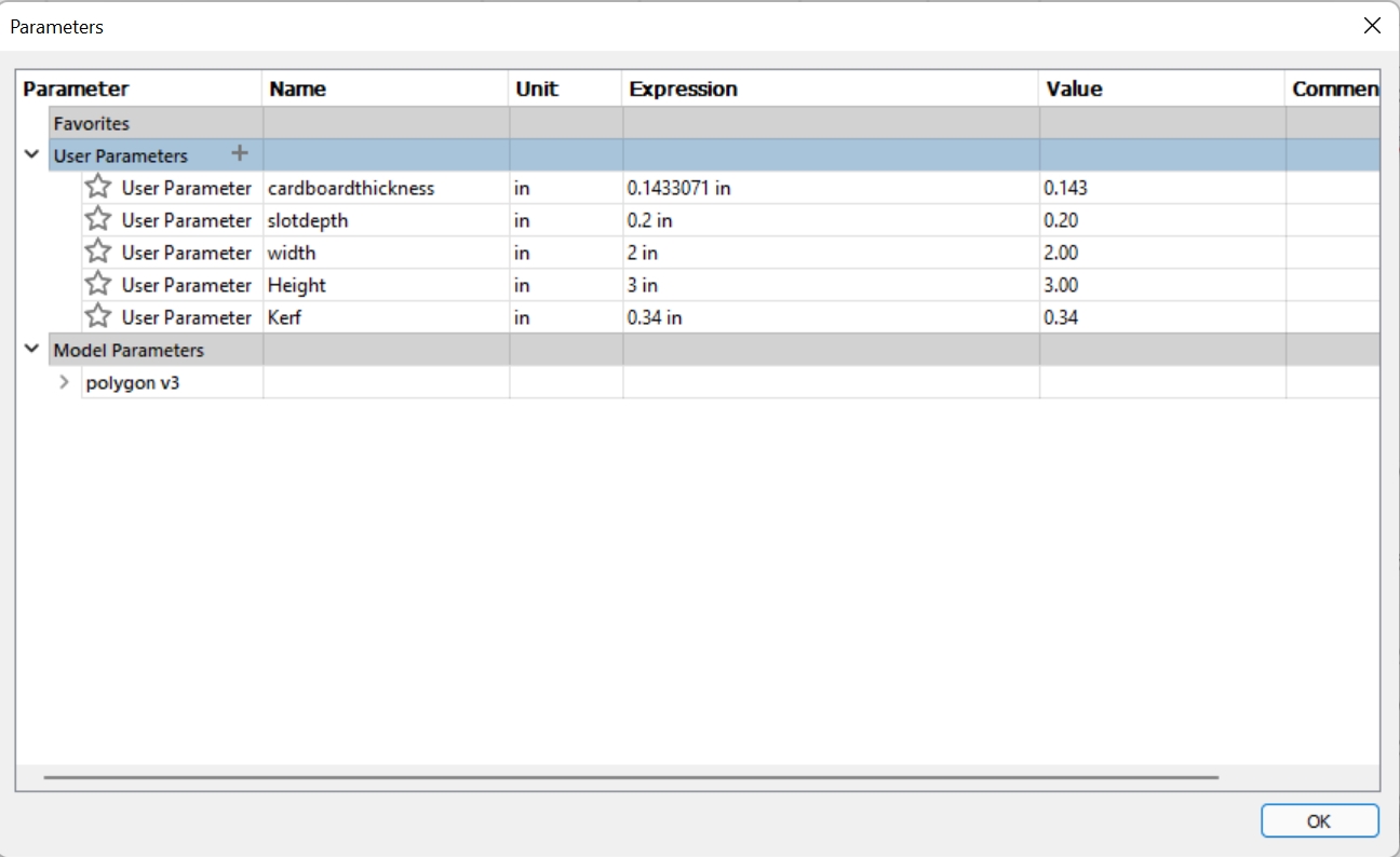
1 . First, I Opened Fusion 360, and clicked Modify > Change Parameters. I entered the values in the table by clicking “User Parameters +”
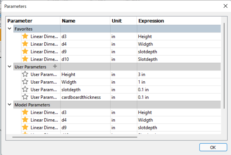 These values can be changed anytime, and the object that you are designing will be redesigned instantly without any extra work of changing every dimension.
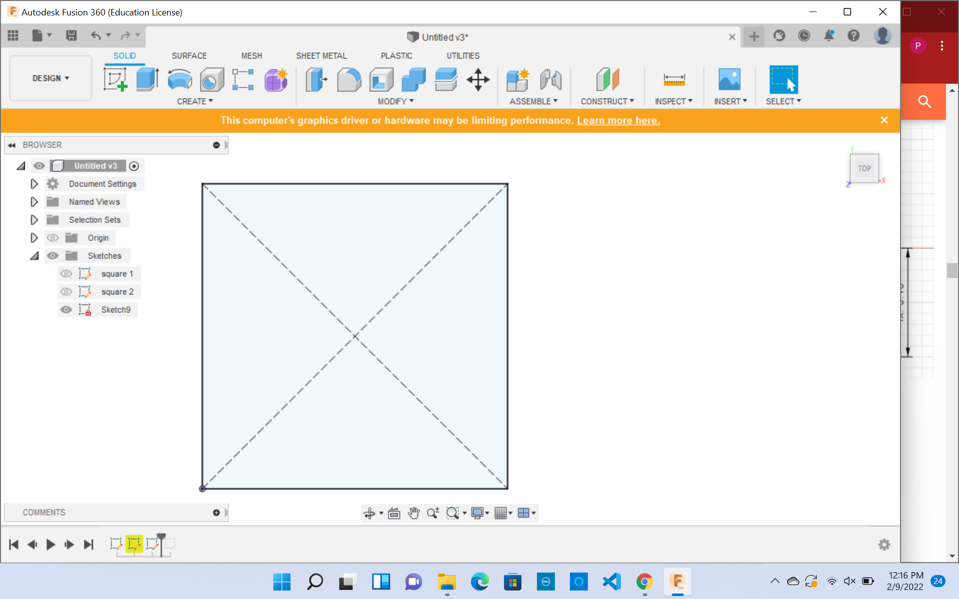
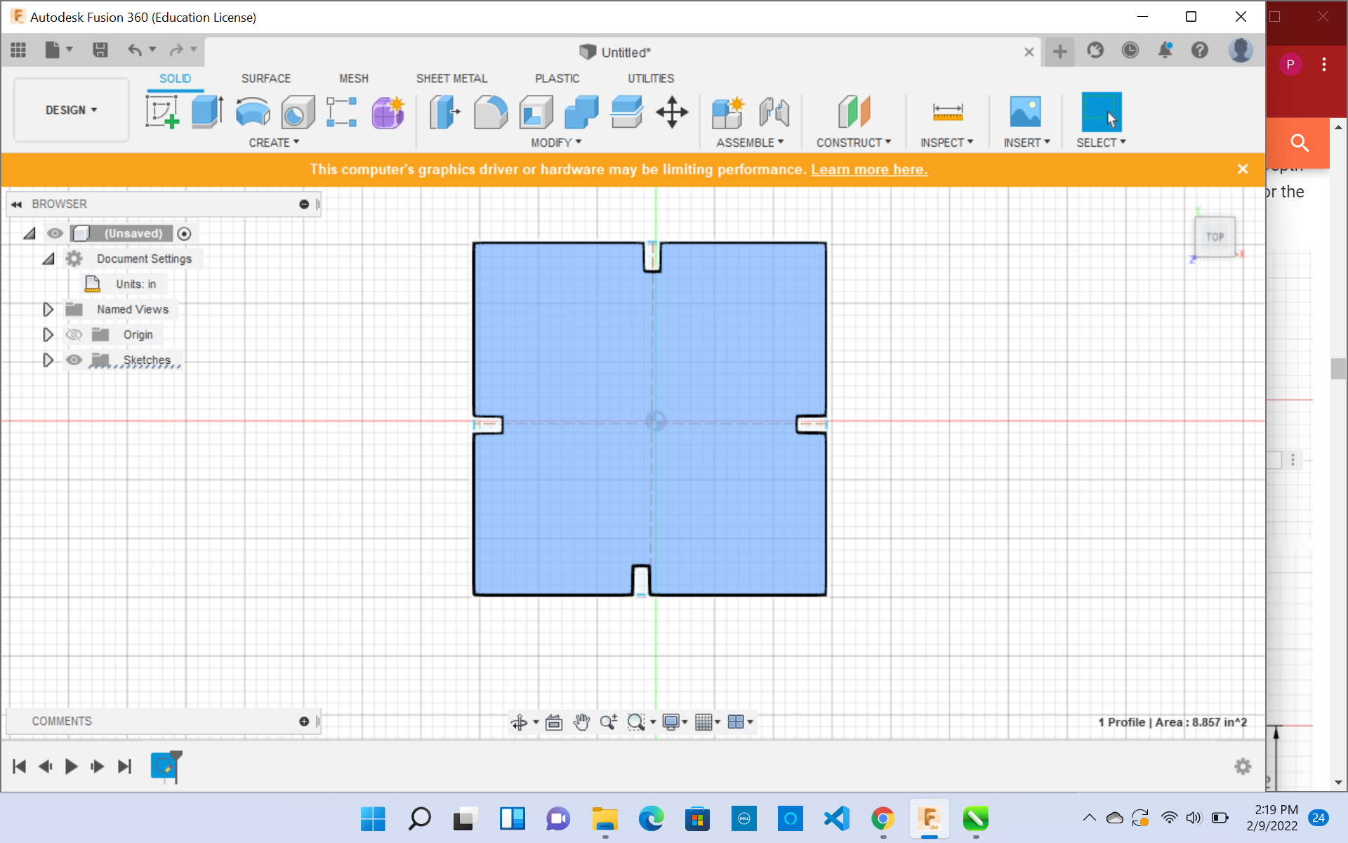
2 . After Setting these parameters, I created a sketch and drew a 2- point rectangle. This rectangle was 1x3 inches, which was exactly what the parameters had been set to in the previous step.
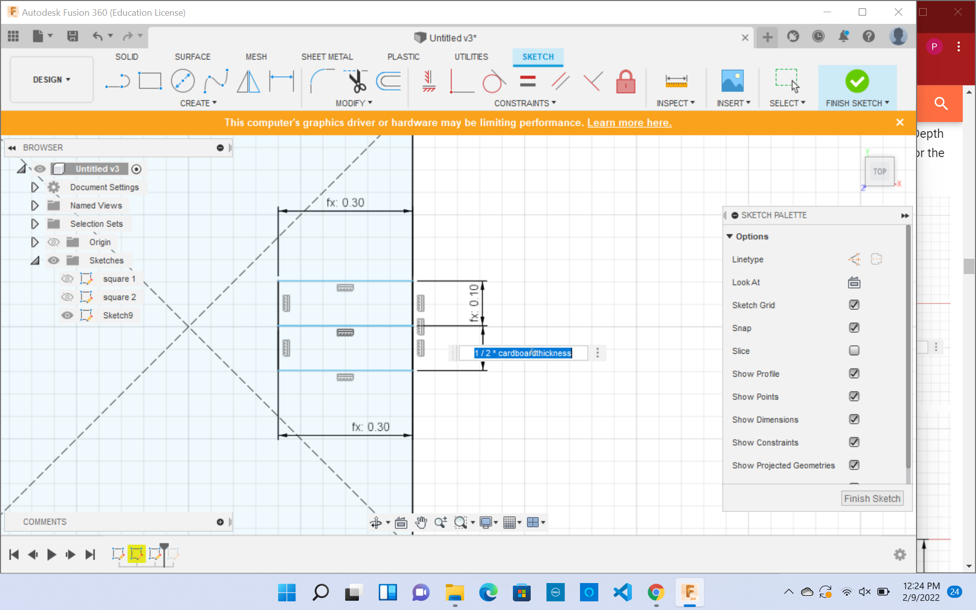
3 . After, I drew two rectangles using the parameters slot depth for the width, and 1/2*Cardboard thickness for the length. This step is to make the tabs that will connect the other cardboard pieces.
Note: Use Calipers to measure the thickness of the cardboard, Or else you will have loose-fitting pieces.
I added a parameter for the kerf of the laser cutter. Kerf is important to account for because it is the width of the laser itself. Kerf can be a little extra material than the original design. Therefore it is VERY important to account for it so when making a press-fit design, the pieces are snug and not too tight or loose.
4 . I then drew construction lines, one vertical and one horizontal. These are so I can mirror the tabs which have been made, without drawing each one out individually.
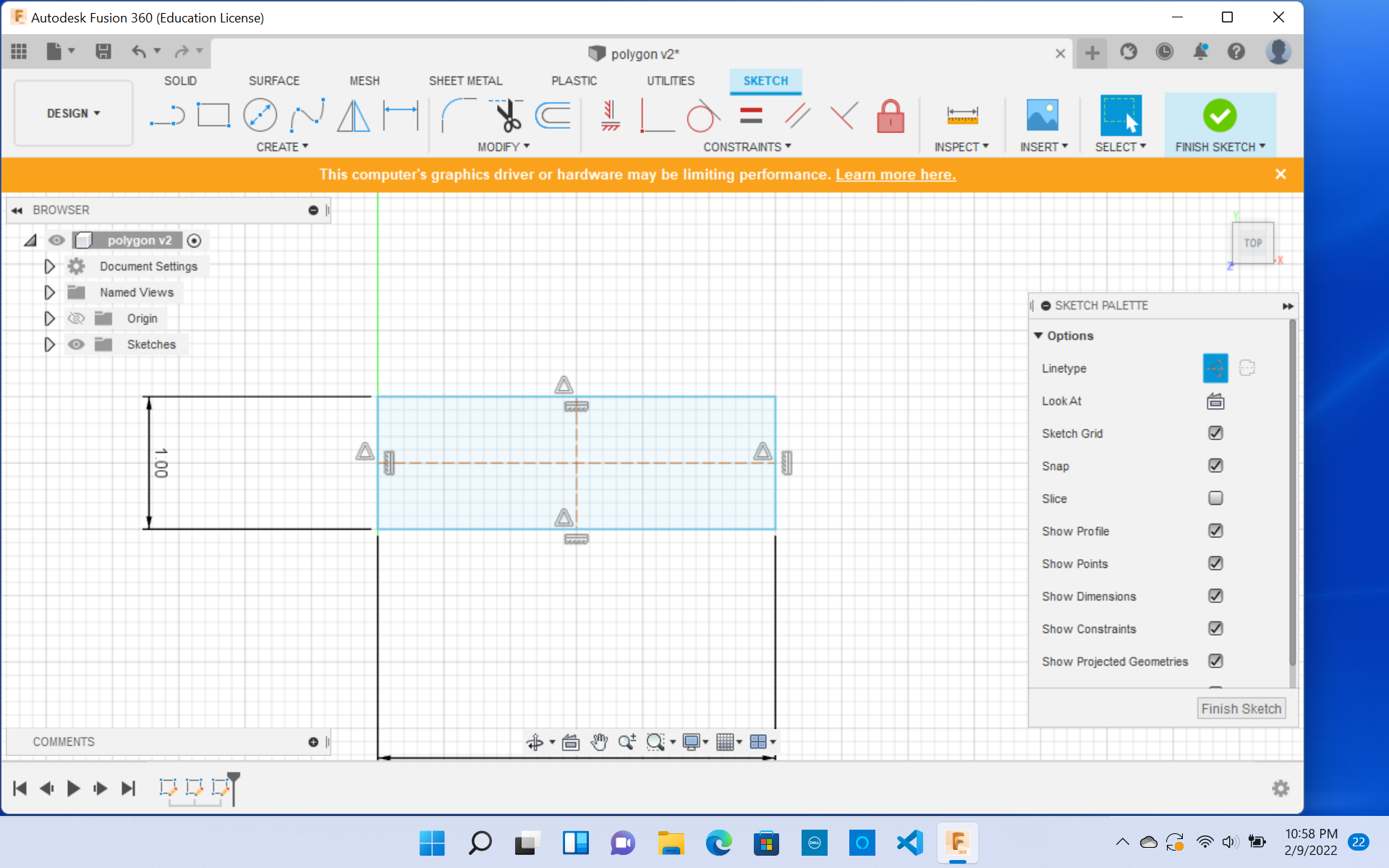
5 .After using the mirror tool, your final product is ready!
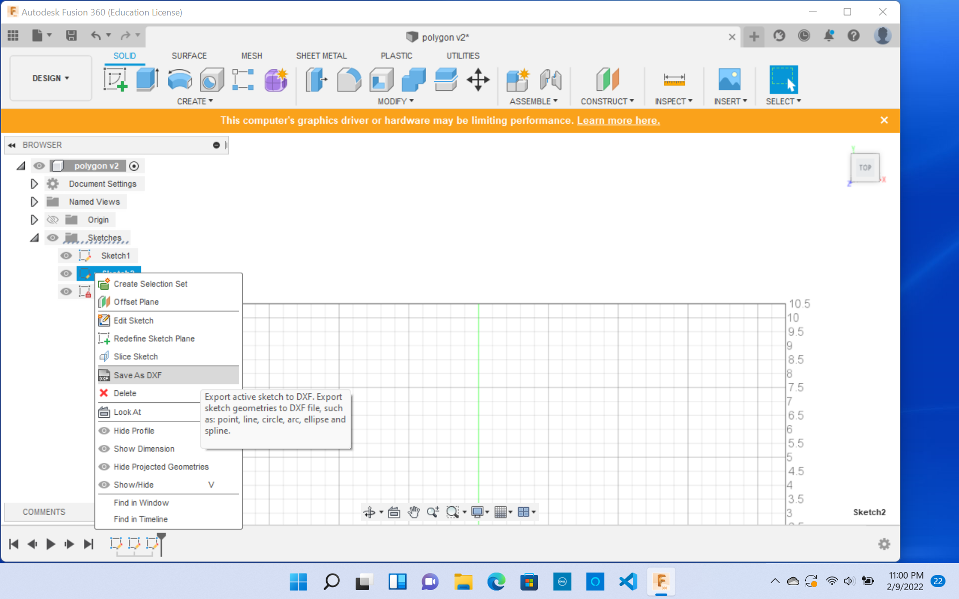
6 . Make sure to export this as a DXL file.
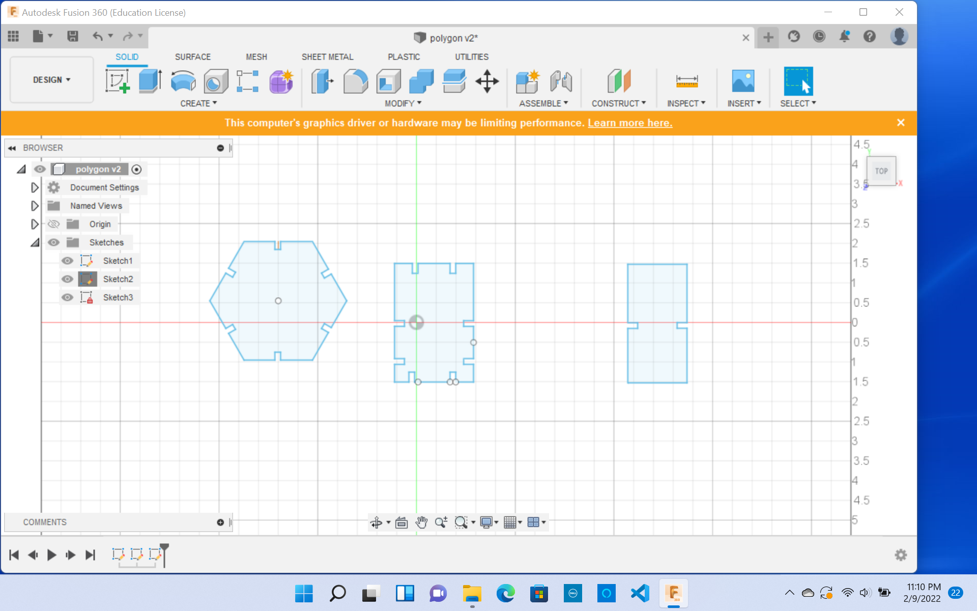
After following these basic steps, I decided to challenge myself and created a hexagon, square, and rectangles for my parametric design kit. I even changed the parametric units to the size I would like. Although, I did face some challenges during this process, as sometimes the numbers I put in would make the tabs of the drawing distorted and misarranged. To fix that would change the width and height of the sketch, but delete the excess tabs which look distorted and create new ones and duplicate them with the mirror feature.
Changed Parametric Units
Final Product of Fusion Design
After designing the file onf Fusion 360, the fun part comes in, Laser Cutting!! After exporting the file as a DXF into my Google Docs Folder, I opened up the workflow on how to use the Laser Cutter in our Fab Lab. This was an easy process, because I have used the laser cutter before for preovious projects. I used my Digital Portfolio, which contains all the projects I have made in the past, and followed the steps on how to laser cutt.
Fusion Pro 48 Laser Cutter Work Flow
After following the laser Cutting Workflow, I successfully cut my parametric design. This was a very satisfying process. Although, before pressing print, I asked one of my colleagues to check if I have leveled the bed properly and have rehomed the axis. The reason I did this was that, during Freshman Year, I had rehomed the axis wrong and ended up bringing the Laser Cutter. Since then I have been scared to use that machine, as I do not want to break it again. Making mistakes is a normal part of life and from that mistake, I learned a lot. I have to start trusting myself, and that is going to be one of my goals through Fab Academy.
Goal: Be confident in my skills and to trust myself.
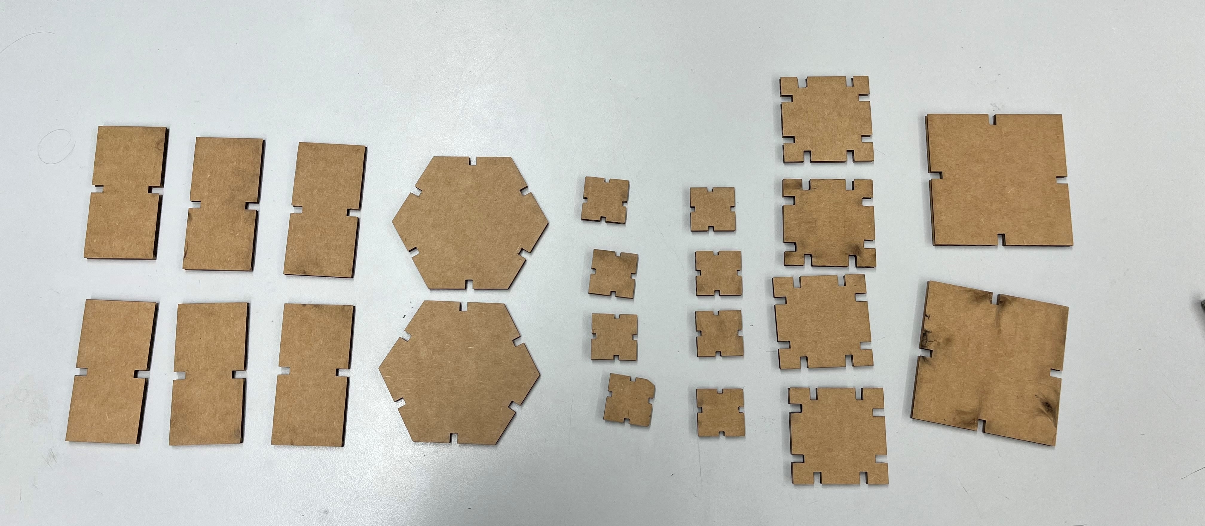
Peices Of The Parametric Design
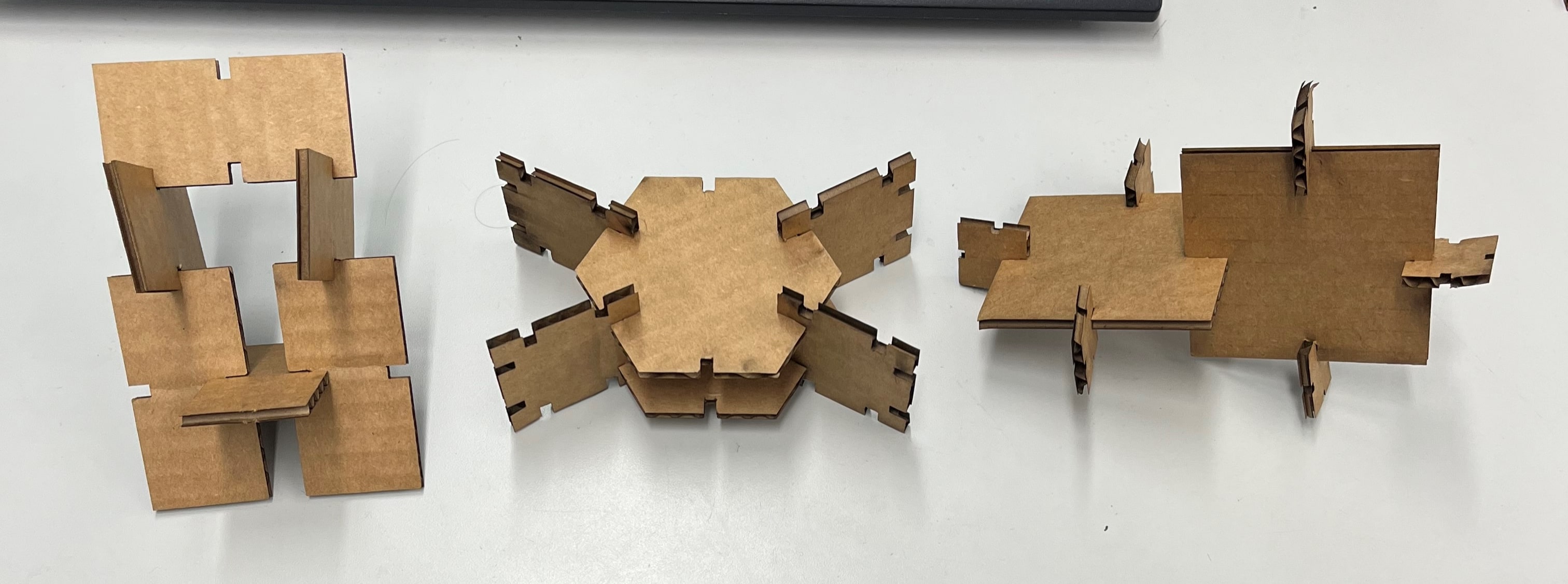
Final Parametric Design
Group Work
This week we also had a group project. In this group project, we characterized the laser cutters and tested each one at the lab for different speeds, power, and focus. My partner Aarush and I worked on testing the Epilog Laser Fusion M2 50 watt. Check out our group site for more details! During the group work for this project, I learned many things. Most importantly how to use the laser cutter. I learned about the different speeds, frequencies, and power, and how they can affect your design. Another aspect that I learned was how to colormap on Corel Draw. I observed how others did it and followed along.
Summary
In this week I learned how to successfully use the Vinyl Cutter and the Laser Cutter. I have used these machines before, so this was all familiar to me. Although I had never made a multiple layer sticker, os this was all new to me. I searched up many tutorials although, my colleague Aaron Logan gave me a simple rundown on how to do it and now I know how to do it. On the laser cutting aspect, I was very familiar with this section and breezed through it, Although, had some hesitations as I expressed my concerns above. This week I also learned how to create a parametric design, this is an efficient way to change design dimensions. I am very glad I learned how to do this because in the future designing stuff in CAD will be 10x easier.
These were my files for this week.