8. Computer-controlled machining
This week’s assignment was to make something by design, mill, and assemble something big (~meter-scale). I also decided to do the extra credit, which was not to use fasteners, glue, and include curved surfaces.
I first designed my file in Fusion 360, although then I realized that my design would be easier to make in cuttle. So I changed my software and designing my file in Cuttle was 10x easier.
These were my files for this week.
Vison of the CNC Mirror
After speaking with Dr. Fagan, he gave me ideas as to how I could make my mirror press fit. I explained my idea to him about how to make the mirror press fit with dowels. He supported my idea, told me to parametrically design my frame, and asked me questions about how my mirror will work.
My idea was to have 4 layers to my frame.
The layers are as follows:
1 . Outter Frame (wavy part) 2 . Inner Frame (rectangular body) 3 . Inner Frame (rectangular body) 4 . Inner Frame (rectangular body)
All these parts would be held with 3/8 in dowels.
Designing Fusion 360 Files
This was a tedious but hard process, due to the number of steps that needed to be taken. To start the process, I wanted to draw a curvy line frame for the outer border of the frame. This was a hard process, as the product looked “weird” and not as I wanted it to look. But I reminded myself that this was just a prototype, so I did not have to make it look perfect.
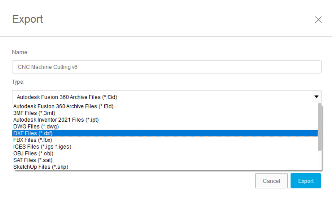
After doing the design, I tried to import it into a.DXF although the design got cut off and wasn’t showing up properly. To fix this I selected the entire sketch and save it as a . DXF again, and it finally worked.
Next, I wanted to cut out the square inner-frame. This was easy to make, all I did was use the rectangle feature and draw a rectangle with parametric features, so it would be easy to change the dimensions later, After doing this I decided to extrude the feature, and then add holes into the frame.
My plan for this was to have an outer frame (wavy part) on the top which would be press-fitted with dowels with the inner frame (rectangular body). This would be to make the frame and create a body it which would hold all my components such as the monitor, sensors, and wires.
After putting all this hard work in, I realized that my design only had to be in 2D. Although I wasn’t happy with the 2D sketches I had made in Fusion 360.
Fusion 360 File
Designing in Cuttle
After experimenting with Fusion 360, I realized that I could have easily designed my mirror in Cuttle. Cuttle is a very nice platform and it is very easy to maneuver, to design anything in Cuttle there are previous designs and tutorials on the website to make your design. I watched A video to learn how to make a parametric design for this specific design.
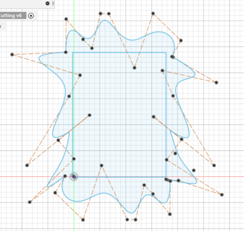
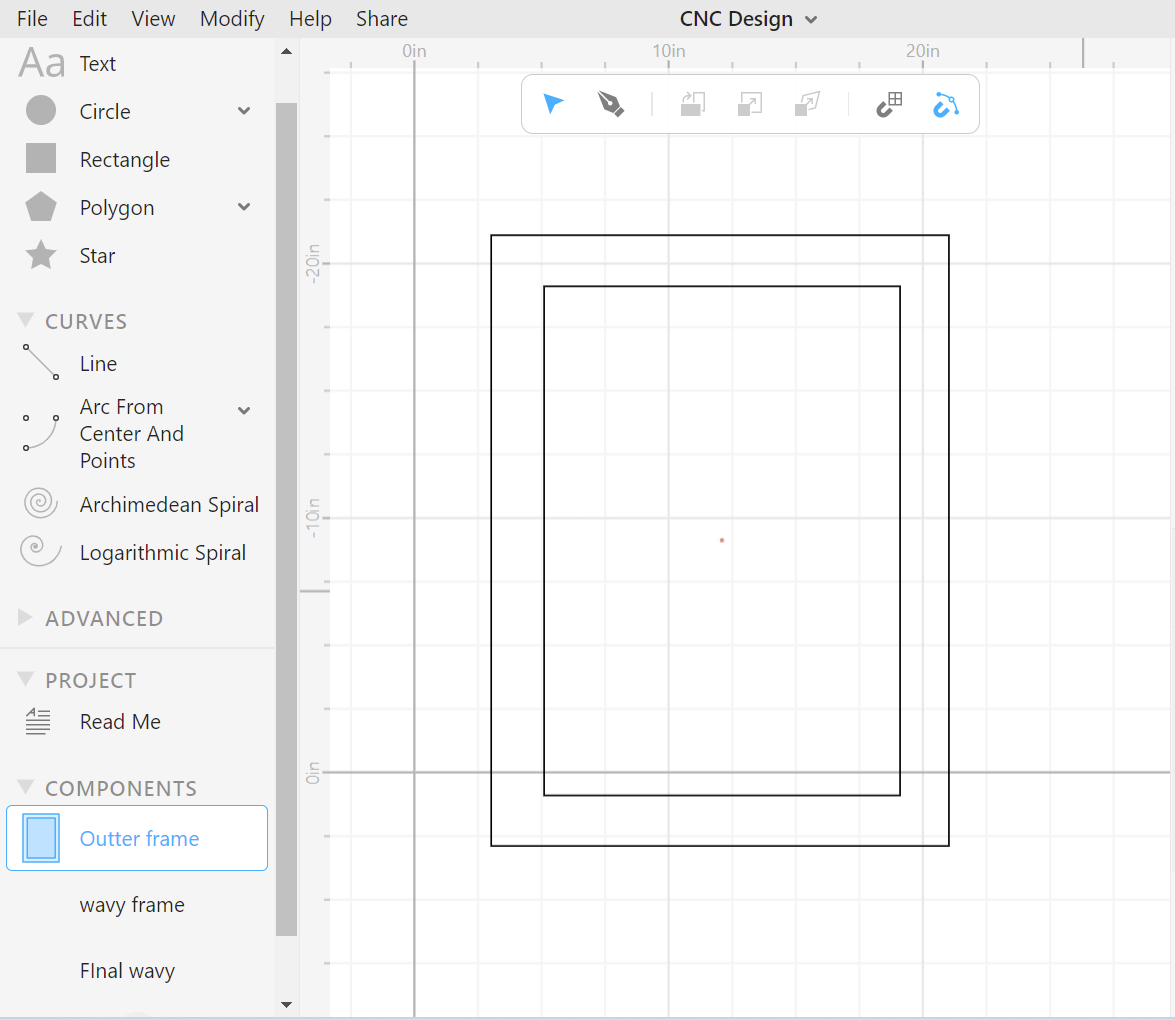
I first started to design the outer frame (wavy part) and which was very easy. I first sketched the rectangle, which I would use as a base to draw the wavy part around. I used the sketch line tool to draw the wavy part which could contort to any shape.
Next, I would start designing the inner frame (rectangular part) This would be hard, as It was hard to match the dimensions of the outer frame and the inner frame. Although, I did it successfully by stacking the outer frame on top of the inner frame to make sure the holes align and the frame would cut successfully.
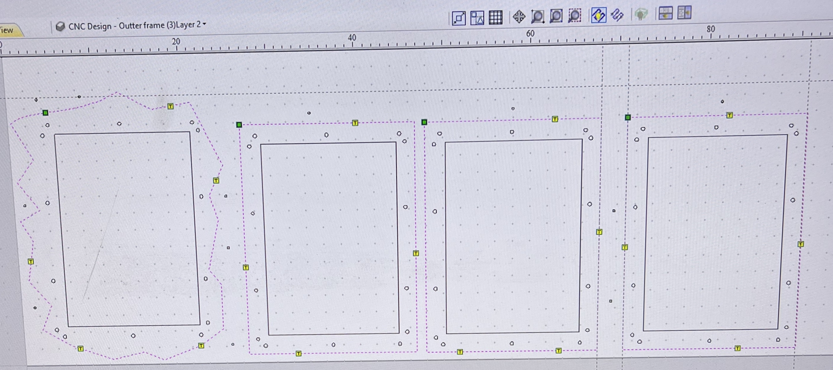
After I would copy/pasted the inner frame 3 times in Aspire, so I would be left with 3 inner frames which would be stacked upon each other to create the depth I wanted which would be 2 inches. The reason I wanted a depth of 2 inches was so I could add all my components in there such as my monitor, wiring, inputs, outputs, etc.
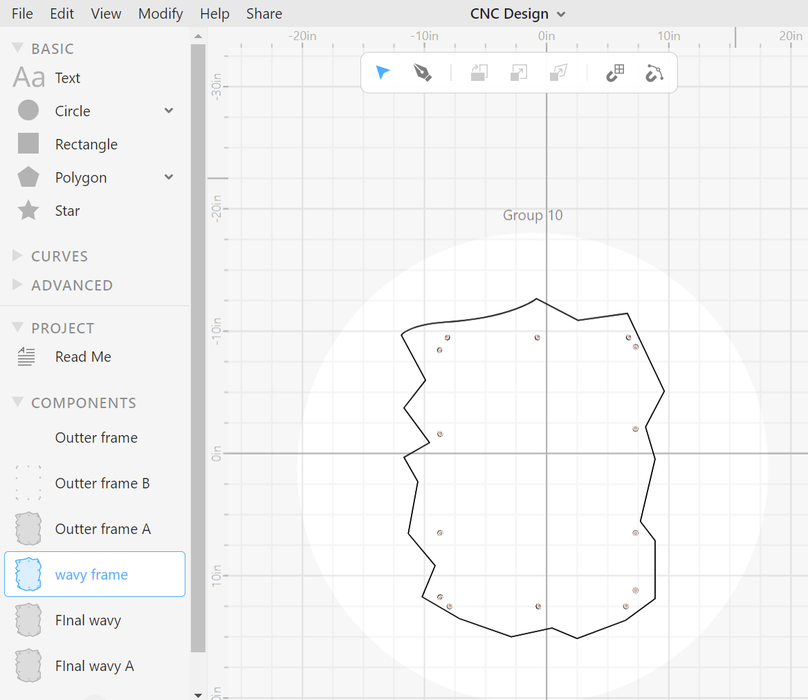
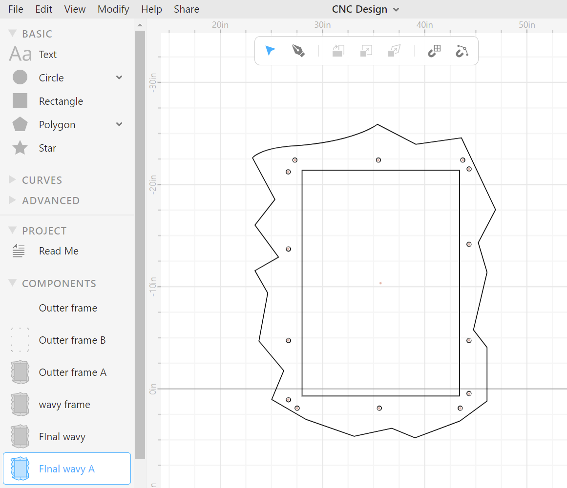
Cuttle Design
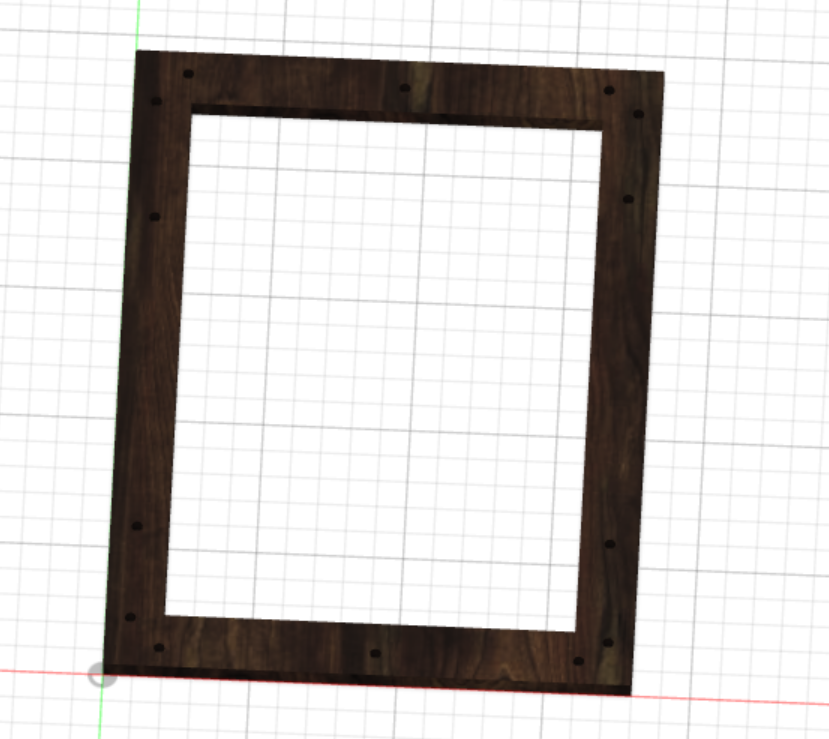
This was the final product, of the Cuttle Design
Testing Design Aspects on The Laser Cutter
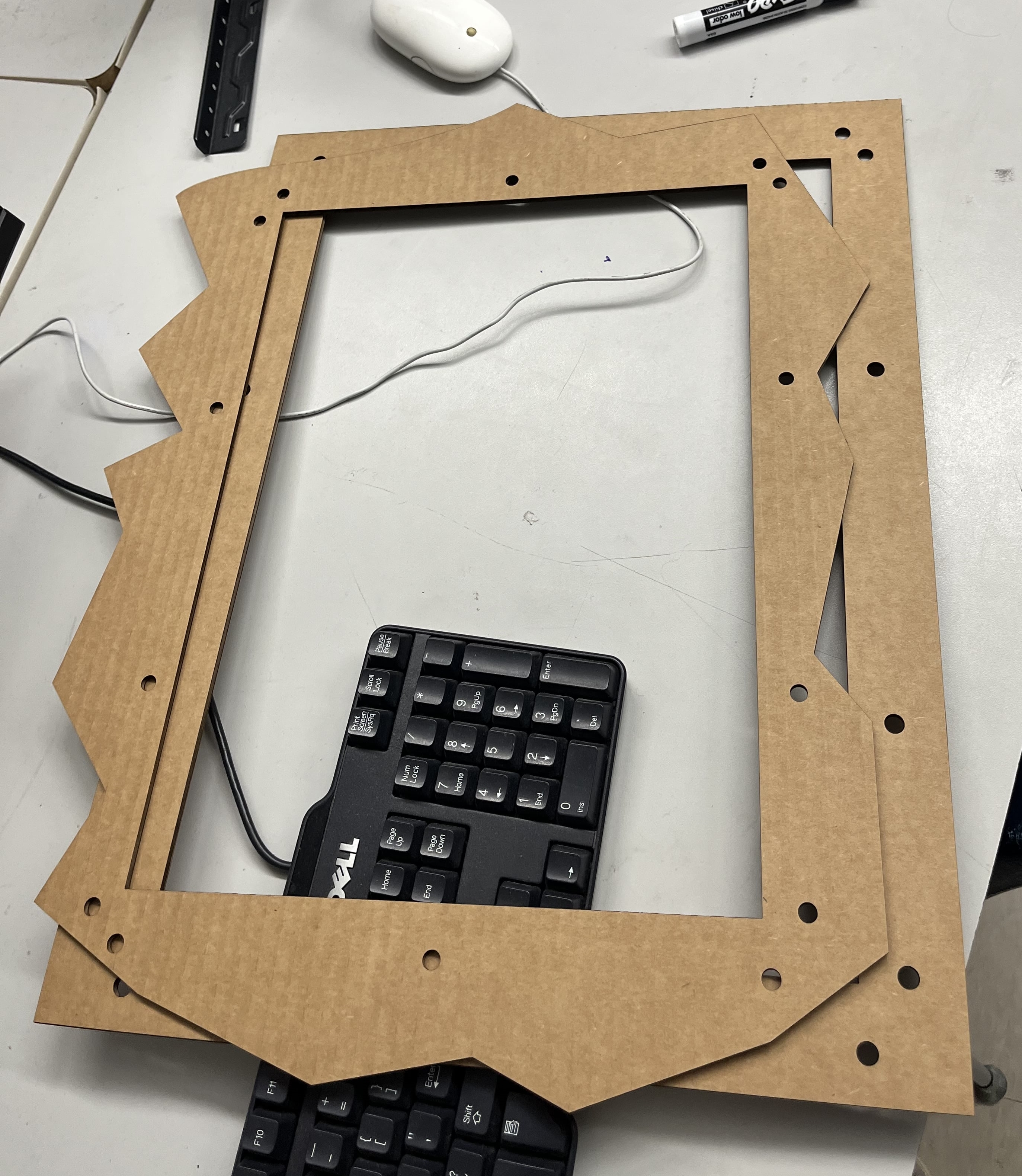
Before cutting on the Shopbot, I wanted to make sure that my design was successful. To check that, I decided to laser cut my mirror so I could gain an understanding of what the final 3D product would look like.
I followed this workflow which I have followed for previous weeks and started my cut.
Fusion Pro 48 Laser Cutter Work Flow
This was an easy process, although I had to scale down the size of my mirror since I did not have bigger-sized cardboard.
The first print was unsuccessful because I forgot to make a square in the center of the outer frame, so the cut consisted of only the wavy part without the square gap in-between.
After going back into Cuttle, and adding a square in Corel draw, I finally printed I out again. This time the print was successful. I linked up the 2 pieces together and made sure that the holes lined up with each other. During the test cut, the outer frame was a little smaller than the inner frame. To fix that, I decided to change the dimensions in Cuttle and was confident that it would work when I was going to cut the shopbot. Although before I cut them on the shopbot, I made sure they aligned properly.
Designing in Aspire
Designing in Aspire is the last stage before cutting on the actual CNC. In this software, you can design 2D and 3D models, as well as, create tool paths. If I wanted to avoid all the extra work which was done with the different software, I would have designed my mirror in Aspire, although I am not very familiar with it. My goal is to use Aspire to design my future files on the CNC.
** Machine Settings in Aspire**
Before importing my files into Aspire, I had to set up the material settings. These settings will be the same when I go to use the Shopbot.
The material dimensions of the shopbot: are 96x48 inches.
The thickness of my material: is 0.724 inches.
To determine the thickness of my material, I used a tab size wooden tool that could slot fit into the wood, and tell the user the thickness of the material.
Due to variations and human error, I set the zero to be from the machine bed. This is so the machine would recognize not to cut itself (the bed).
** Importing files and Configuring Toolpaths**
In Aspire I imported my file and then started to manipulate its different tool paths. I used 3 different types of tool paths.
- Pockets
- Profiles
- Drill holes
What Are The Functions of These Different Tool Paths?
| Type of Toolpath | Function |
|---|---|
| These tool paths do not fully cut through the material. They are usually used for holes or designs which do not want to be fully cut through. | |
| Profile | These tool paths cut through the material and can be thought of as a vector cut. |
| Drill holes | To keep the materials from shifting and moving, it is important to screw the material down to the machine. To make this easier and to prevent the wood from cracking the machine builds drill holes that make it easy for a screw to attach the material. |
For the outer parts of the frame, I used a profile cut and use the method of cutting on the outside of the line. Next, I used profile cuts to make profiled holes into the outer frame (wavy). I planned on these holes to not go through the front, so there is a cleaner look for the viewer.
Here is a picture illustrating how to set up a tool path.
Step By Step Guide On How To Set Up Toolpaths
1 . Once all your material settings and files are ready to go, choose what type of tool path you want.
2 . Once you have decided the kind of toolpath you desire, click on the design where you would like to cut that specific toolpath.
For example, If I was setting up my 2D Toolpath for the outer mirror (wavy side) I would click that component.
3 . Next, after clicking the desired design on the left-hand side of your screen click toolpath. A whole menu should come up, and you can decide which one you had previously decided in Step 1.
For example, I would click 2D Toolpath.
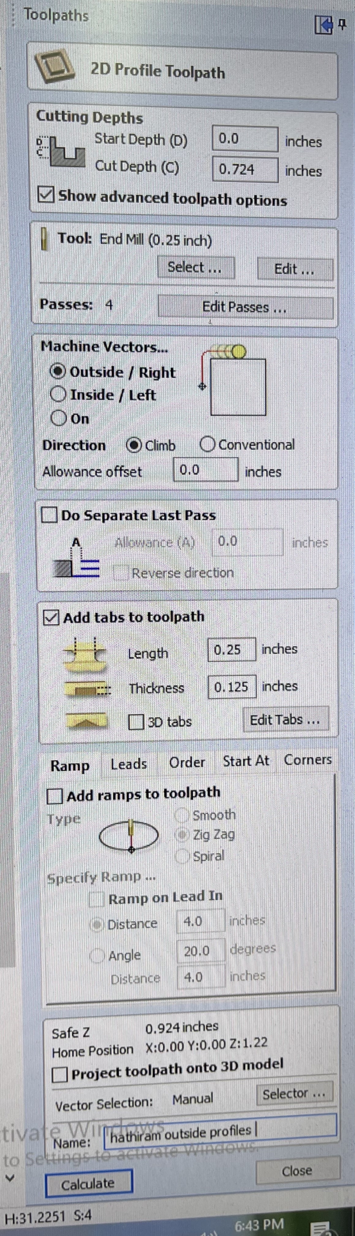
4 . Once you have clicked the toolpath you wanted, it will prompt you to add in some values for Cutting depth, Tools, Vectors, Tabs, etc.
Referring to the picture above, I filled out the values as to how they would look on my design.
When cutting profile cuts, it is important to set the section “Machine Vectors” to Outside. This is because you don’t want to lose material. The other options such as inside will make you lose small bits of material.
5 . Once everything is set, export your files properly and cut your design on the Shopbot!
Here is a quick/helpful checklist you can use to make sure you have set everything correctly.
- Correctly set materials
- Imported your file
- Chosen proper toolpaths
- Named your file
- Exported the file in the correct format
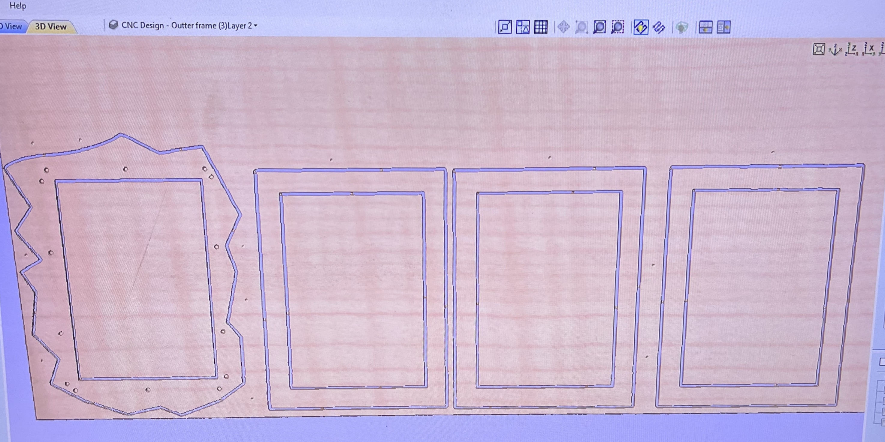
Final Caluculated Toolpaths
Using Shopbot To Make My Mirror Frame.
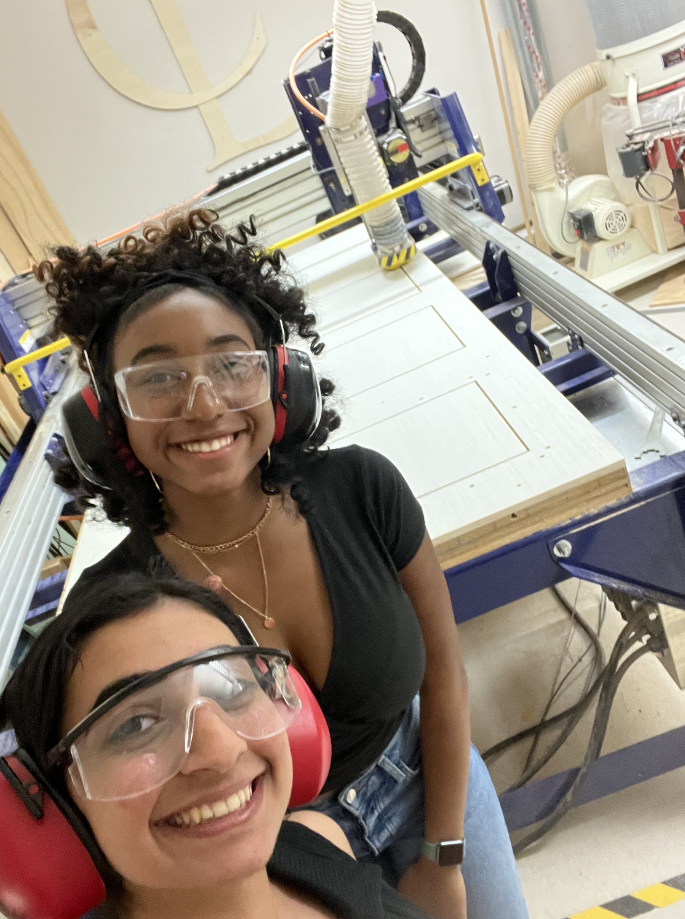
Once I was ready will all the tool paths and was confident that my design will work, I asked my Instructor Mr. Dubick to check if my work was right since I was afraid to waste material and mess up my work. safety glasses and headsets. Since my hair is long, I tied it back with a hair tie.
I followed this workflow thoroughly, so I could have a successful run.
Here are some pictures from the process of setting up the CNC.
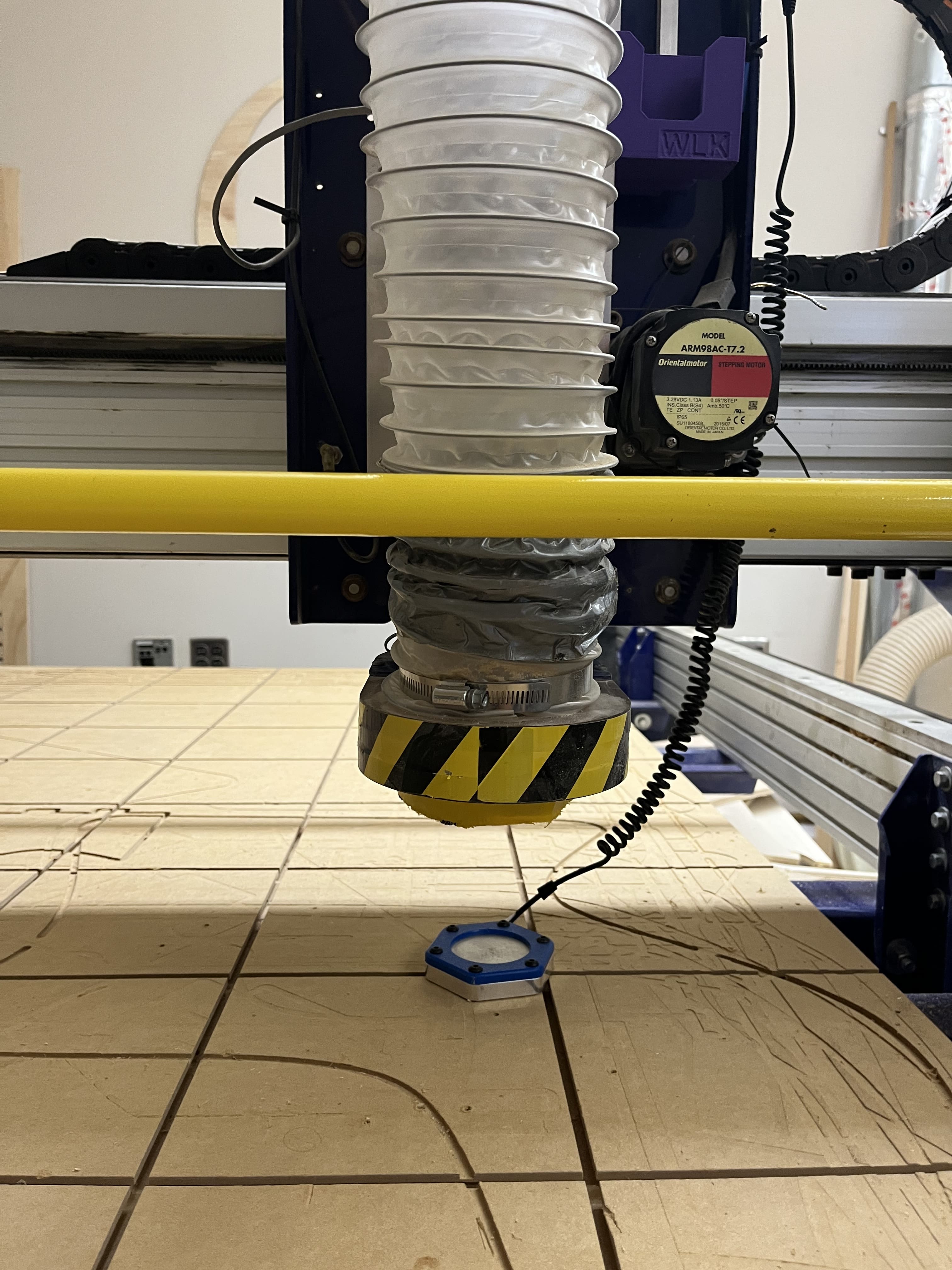
CNC Drill Holes
After setting up the CNC, I tested my design to fully work by running aircuts, which is also written in the workflow. These air cuts helped me catch the small mistake which I had in my design. This mistake was that I had profile cut holes, instead of pocket holes for the outer frame of my mirror. To fix this before it was too late, I went into Aspire and added a pocket toolpath for the holes which wouldn’t be fully cut on the outer frame.
Video of Aircut
After Air cutting and making sure everything went according to plan, I finally started to cut. This cut took around 1 hour. It is crazy how a cut can only take an hour but requires SOOOO much preparation.
Pocket and Profile Holes
Profile Cut for Inner Section Frames
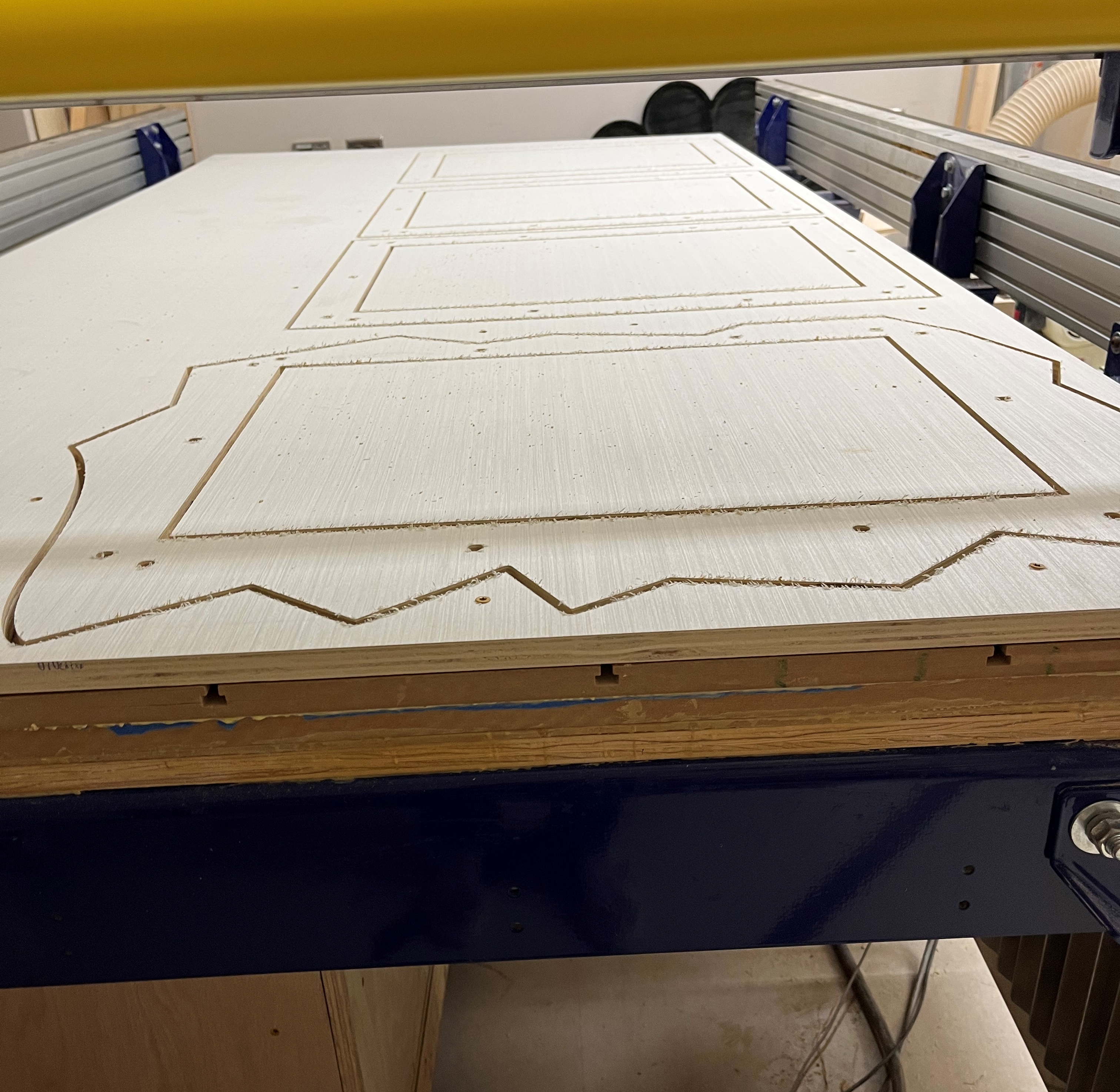
Profile Cut for Outter Frame
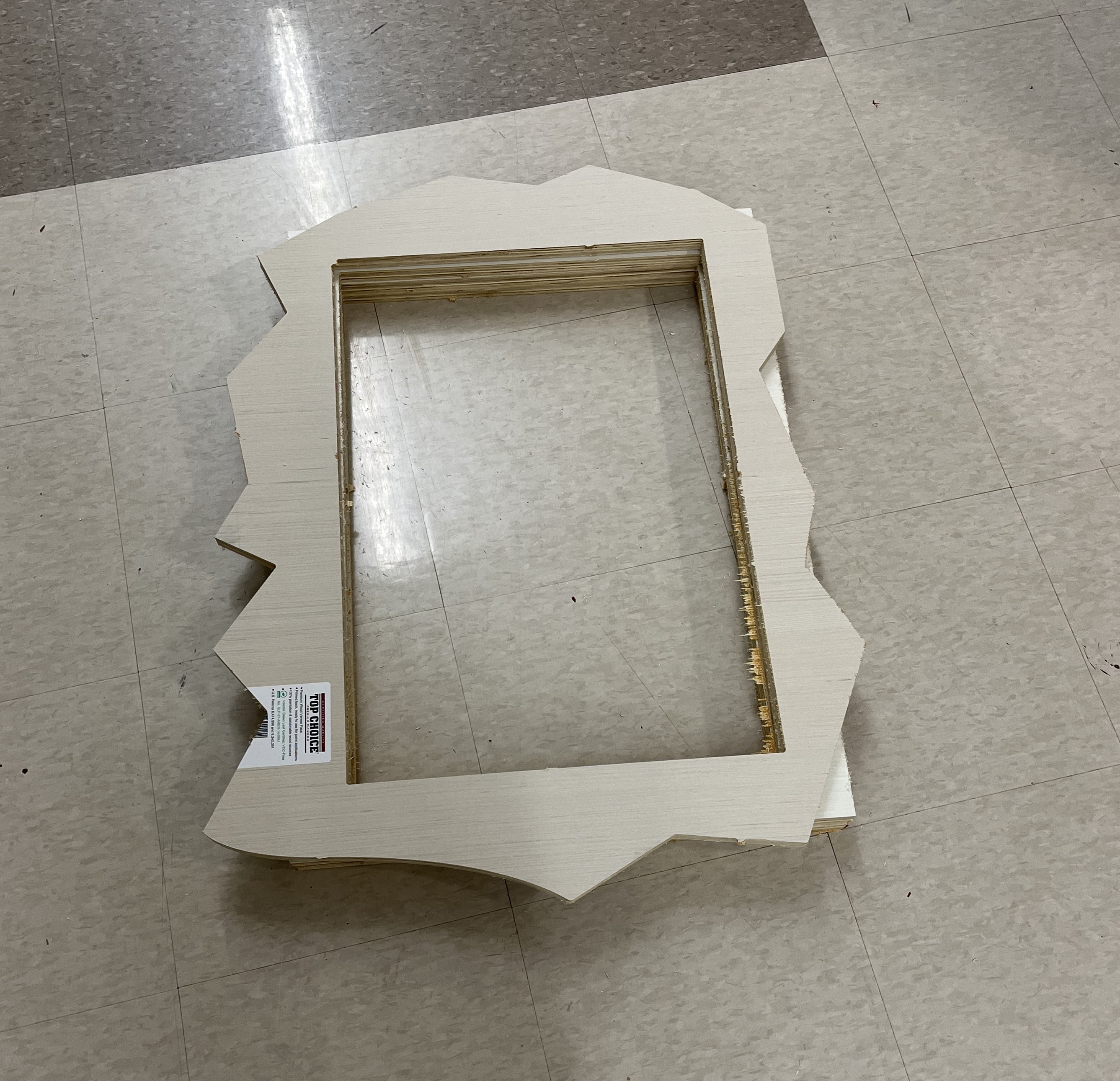
Final Product After CNC (no post-processing yet)
Post Processing
After cutting the pieces, it is crucial to post processes and to carefully extract all the pieces from the CNC bed to the structure you want to make. First and foremost, I wanted to sand down the surfaces of my mirror. There were many splinters and rough edges which I wanted to smoothen to it is easier to manipulate and hold.
I used a hand sander to smoothen the surfaces. I used different grit sandpaper. Ranging from 60- 1200 grit. I slowly worked my way up from the different grits. This process took a while because I had 4 components that needed to be sanded.
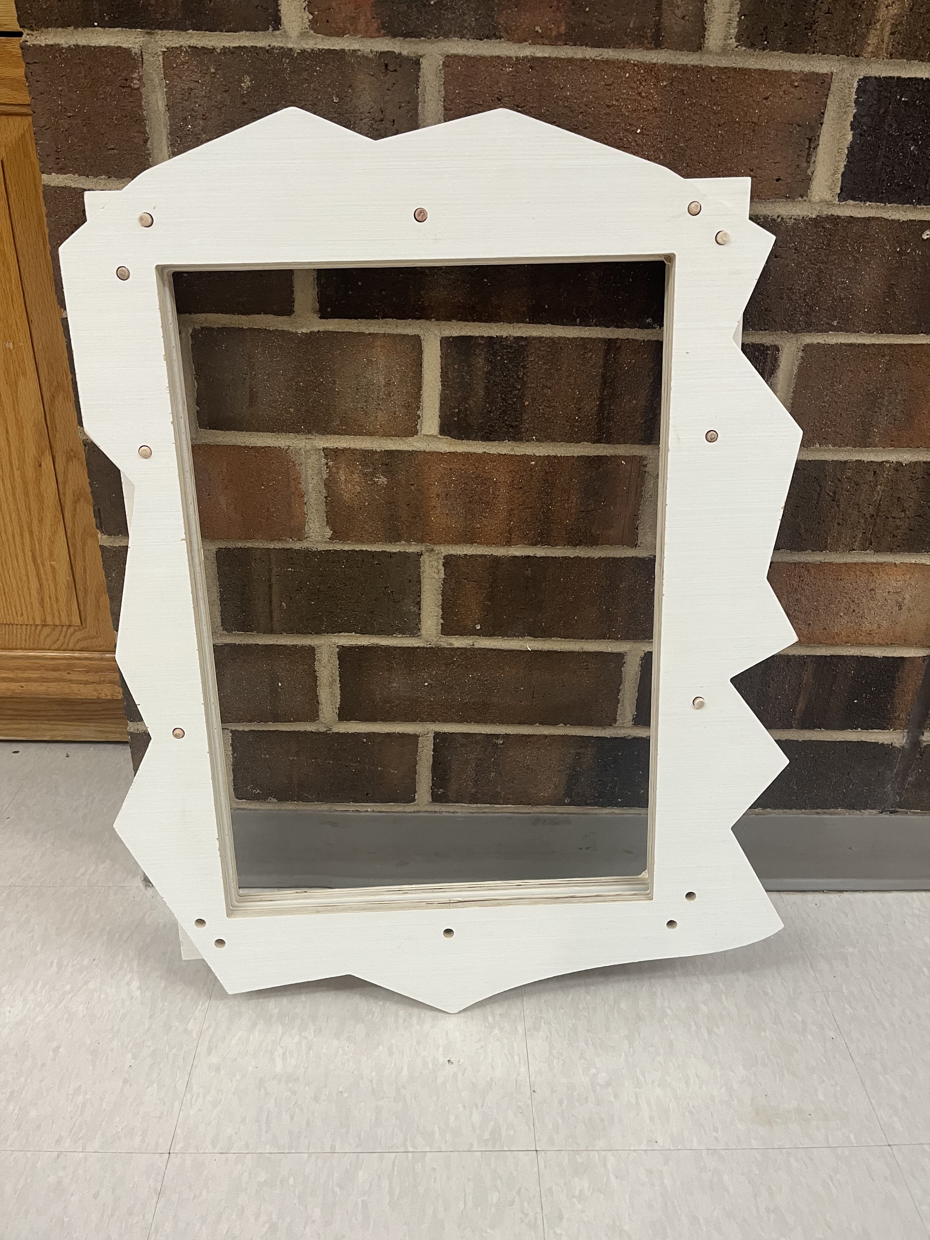
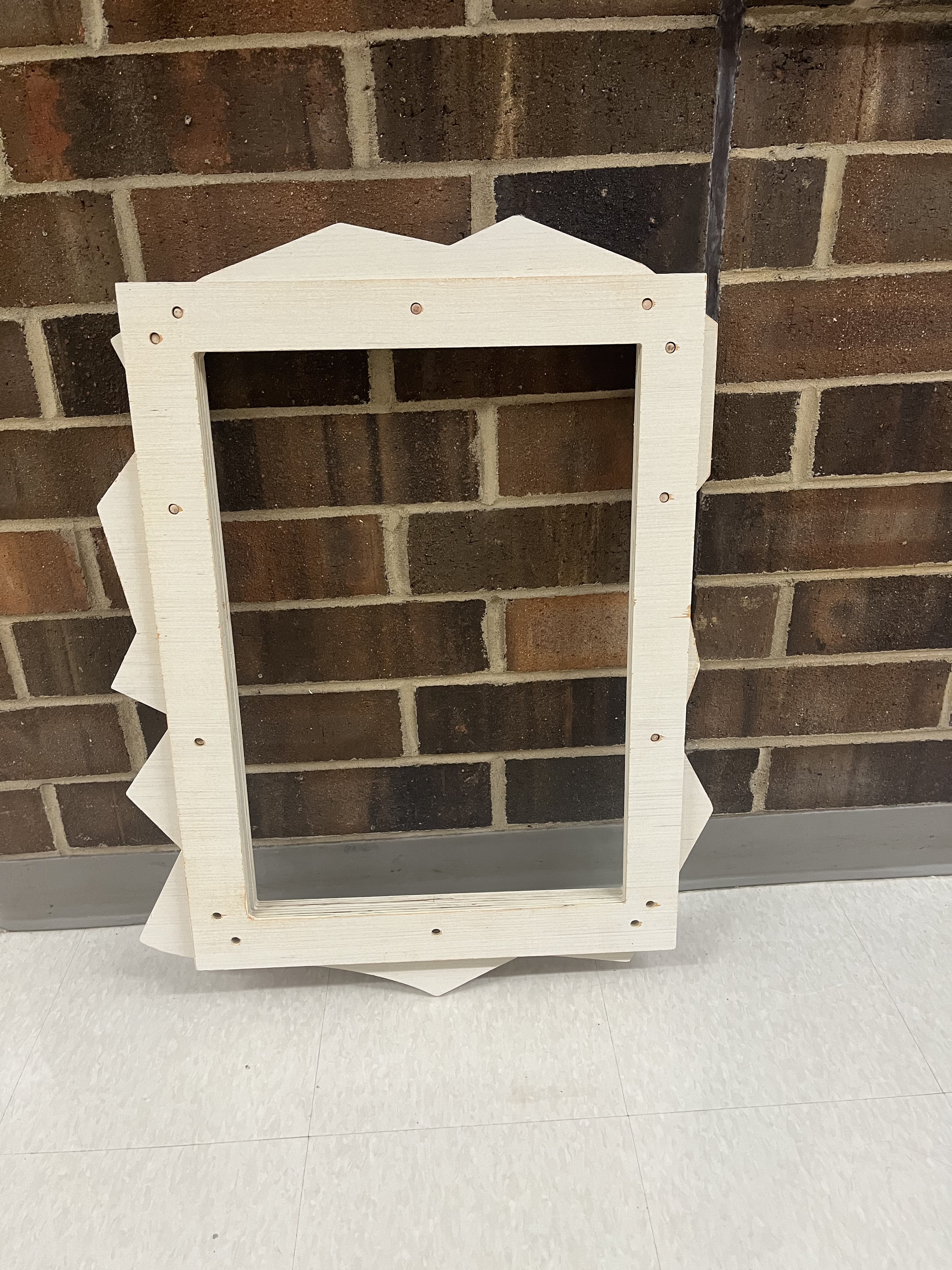
After sanding these components down, I ordered dowels from home depot. I had designed my holes to be 3/8 inches in diameter. Although when I went to assemble the frame I realized that the dowel was not tightly fitted in. some of them slipped out. Another mistake that I made was that I bought short dowels. This was an amazing learning experience for my final project. I learned that I would need longer dowels, so I would not have a gap in between my stacked frames. To fix this problem, I decided to only have one layer of the stack. This consisted of the outer frame (wavy) and the inner frame.
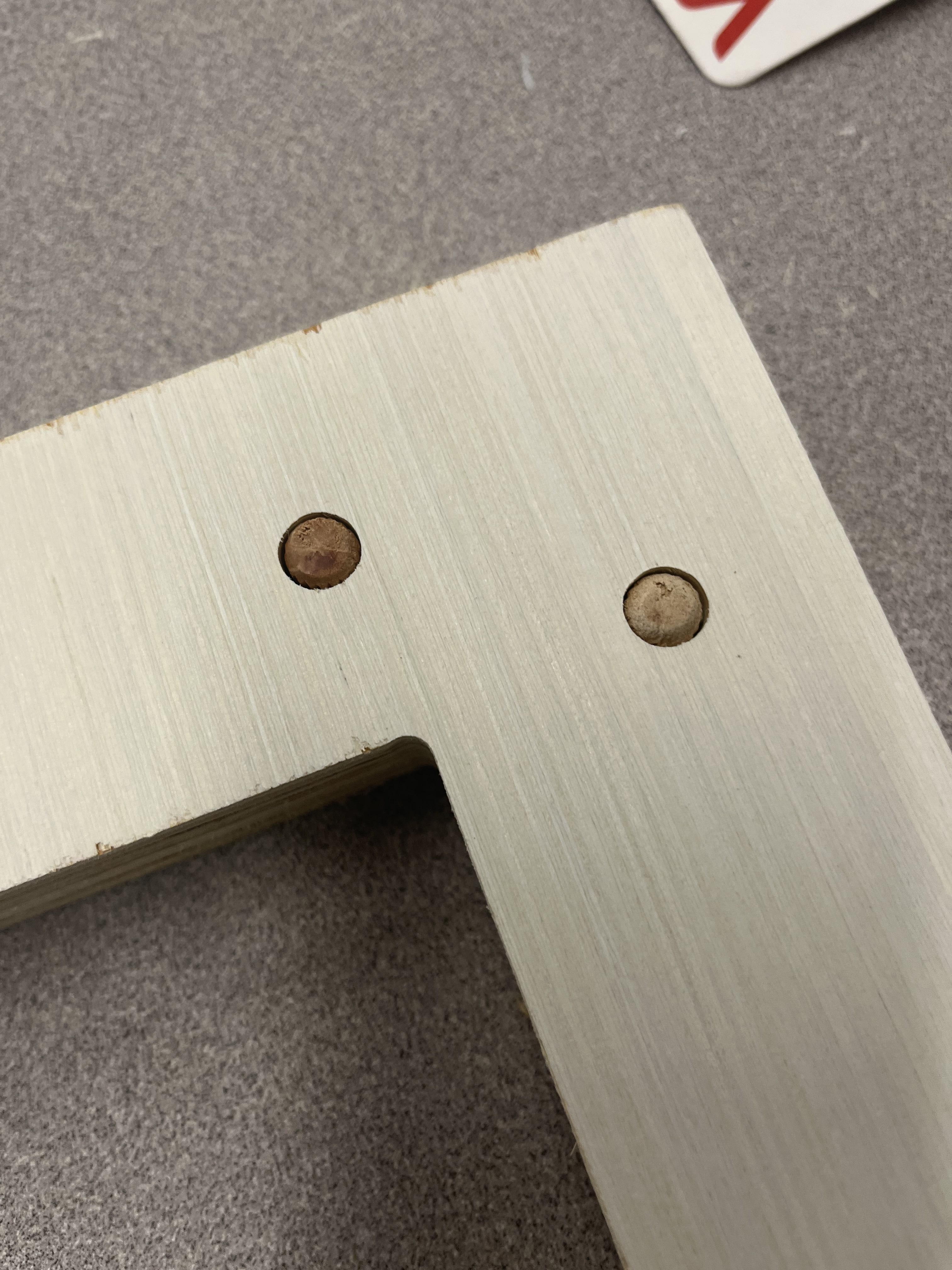
There was another problem tho… the outer frame did not have full holes, they had only half, which was the pocket cut, This was a problem because I realized that each hole was not the same. The inner frame holes did not properly align with the outer frame holes. OH NO! I thought that I would have to redo my cut, although my instructor, told me that I would just drill through the holes instead, and that would solve my problem.
This sounds like an easy process, although I did not want to make any more mistakes, so I decided to make a jig with the correct diameter of the holes that I wanted to drill. This was to eliminate any human error and would result in a perfect hole.
To first create the jig, I used the Hole Hawg, to create the holes. This machine is a machine that can drill holes at 90 degrees. I used a piece of wood, utilized a 3/8 inch bit, and drilled a hole straight through.
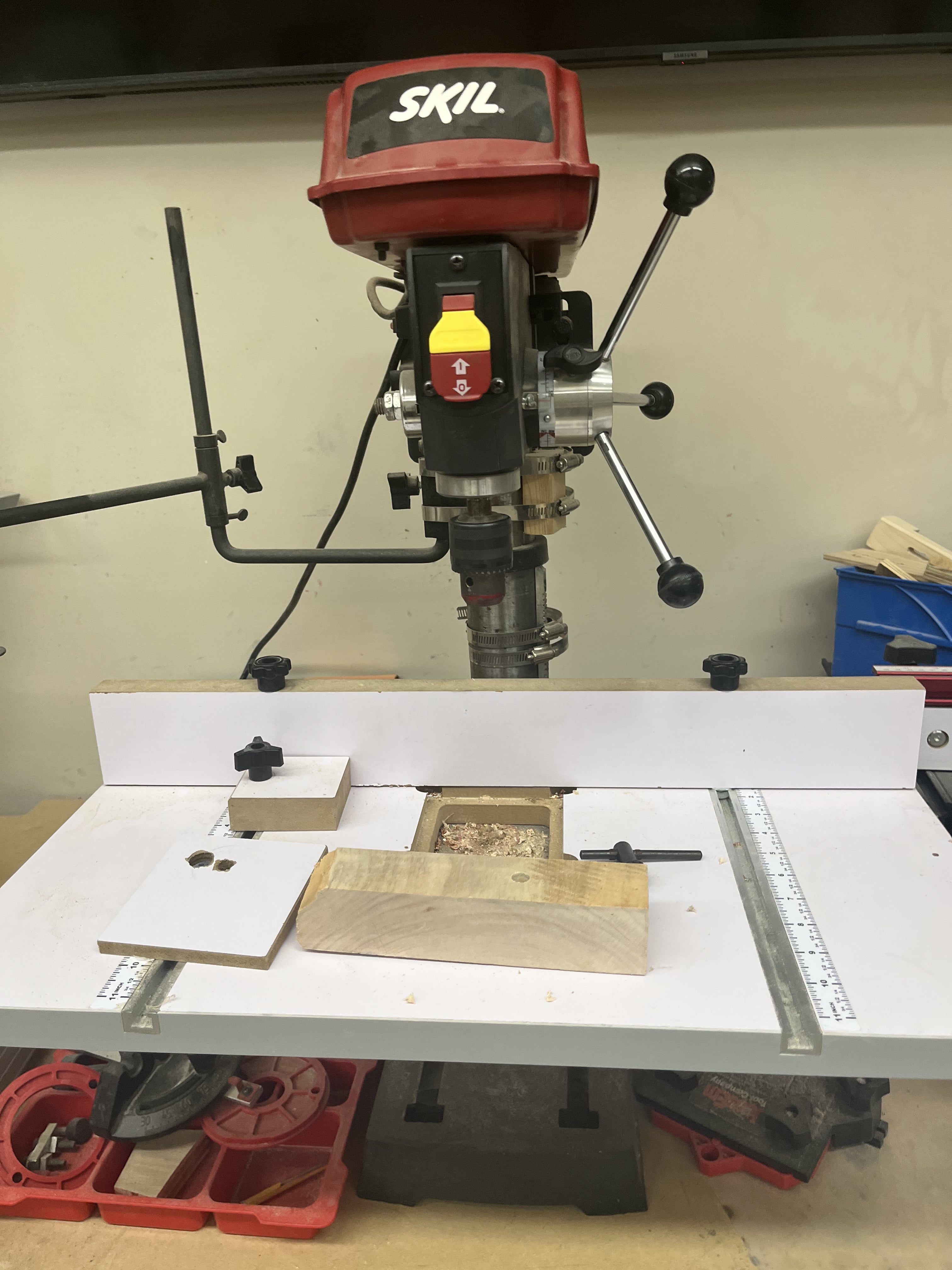
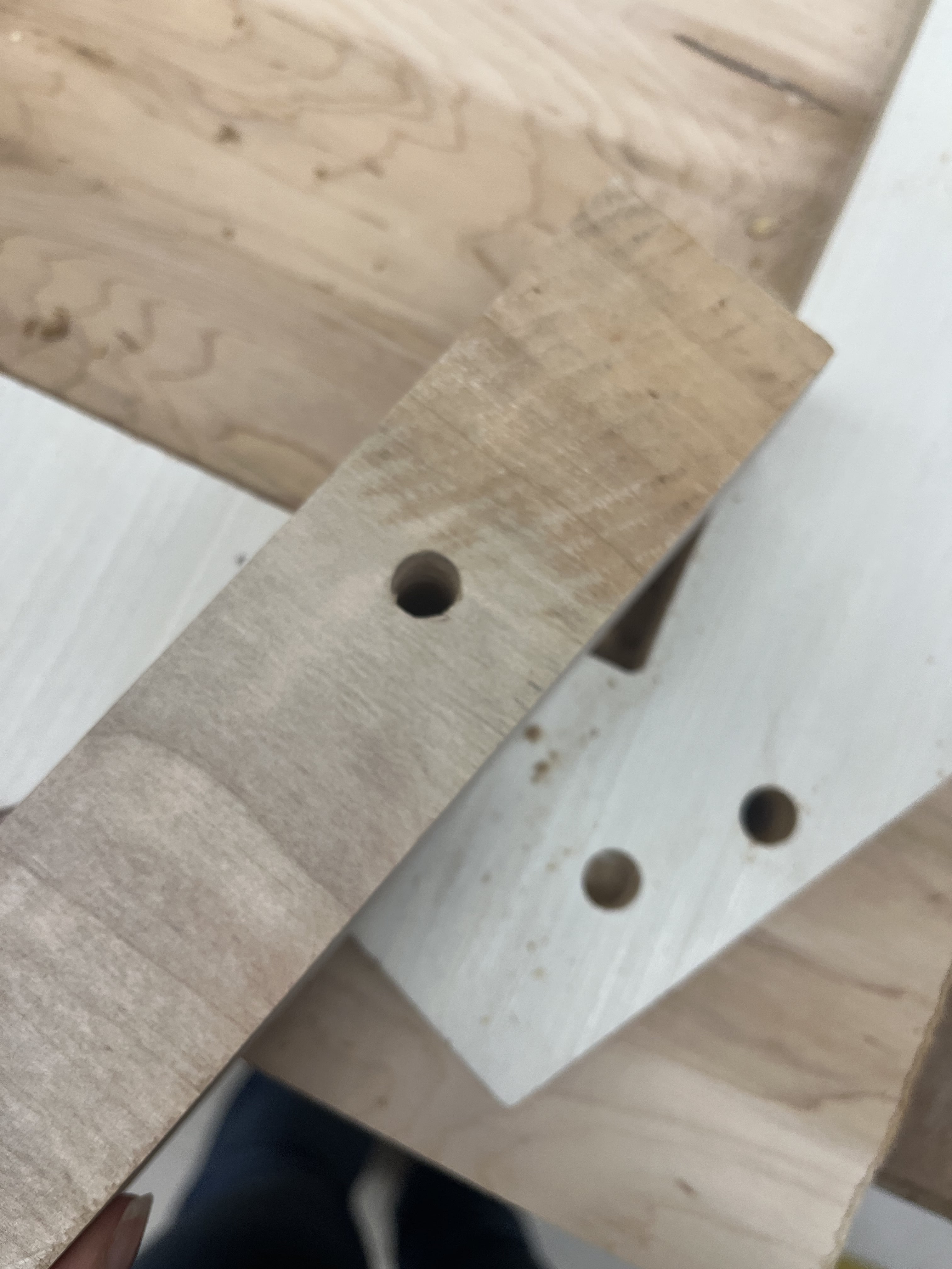
After using the machine to create the hole, my jig was finally made, I used clamps to clamp the jig down, and started drilling the holes into the outer frame. At first, the drilling was rough, although as I got more comfortable with it, I became much more efficient and better.
Here is a video of me drilling a hole into the frame.
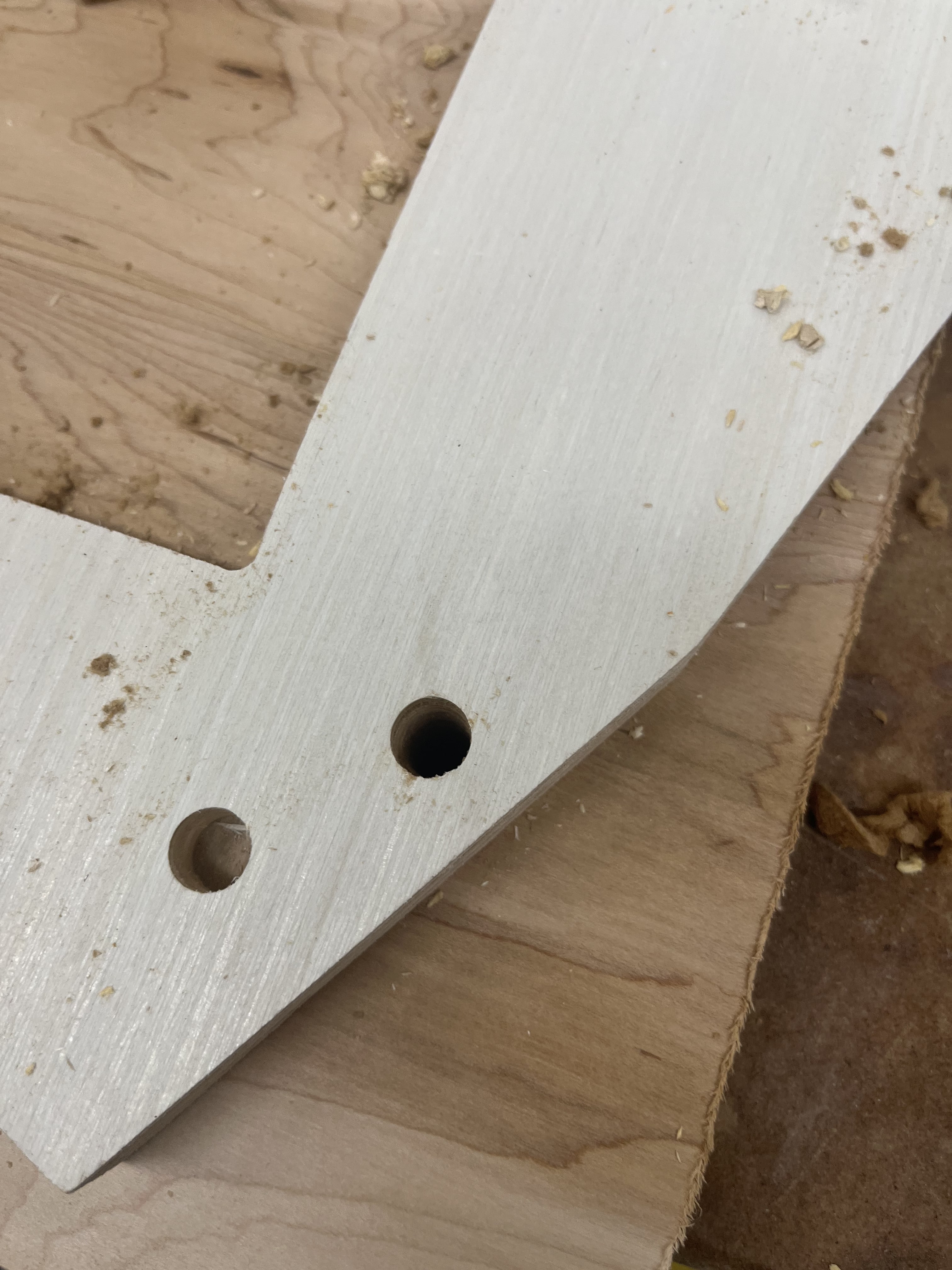
After the holes were drilled I realized that the dowels fit perfectly into the outer frame. This got me thinking that maybe the holes designed on the inner frame are a little bigger than the ones on the wavy frame. I press-fitted some dowels into the wavy frame and one inner frame and they fit snug. This was a HUGE accomplishment for me and I couldn’t be prouder.
Final CNC Cut Mirror
Summary
This was one of the most stressful, yet smoothest weeks. My cut went amazingly and so did my design process. It was my birthday over Spring Break, so I had traveled missing an entire week of Fab work. This put me behind, although thankfully I have had time to catch up. I did not make many mistakes this week, although I learned SOOO much.
One of the main things that I learned is to calculate dimensions VERY thoroughly. There were many times when I wouldn’t account for something, although since this was my first time I am going to be a little easy on myself.
Another thing I learned is to trust myself, most of the time what I think in my head is usually right. You k=migt be seeing a pattern now… almost every week I document saying that I should trust myself, although it is hard because most of the assignment to me is new and I have never done them before. Therefore, I always try to check my work before I use a machine.
I first perceived this week to be the hardest, although with confidence, a good attitude, and a knowledge of this material anything is possible. I am very proud to say that I overcame this week having learned a lot, and building the confidence to use the Shopbot in the future.
These were my files for this week.
Group Work
For this week’s group works my classmate, Jadaand I research the materials which the CNC can cut. During this research, we found many cool materials and things that can be made out of these materials. To check out more, see our group website